background image

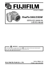
DIGITAL CAMERA

FinePix S602 ZOOM

SERVICE MANUAL

U/E/EG-Model

FUJI PHOTO FILM CO., LTD.

Ref.No.:ZM00441-100

Printed in Japan 2002.5(NT)

WARNING

THE COMPONENTS INDENTIFIED BY MARK 

 IN THE PARTS LIST SHOULD BE REPLACED

ONLT BY THE COMPONENTS SPECIFIED IN THE PARTS LIST.

RISK OF FIRE AND ELECTRIC SHOCK.

Summary of Contents for FinePix S602 Zoom

Page 1: ...AL U E EG Model FUJI PHOTO FILM CO LTD Ref No ZM00441 100 Printed in Japan 2002 5 NT WARNING THE COMPONENTS INDENTIFIED BY MARK IN THE PARTS LIST SHOULD BE REPLACED ONLT BY THE COMPONENTS SPECIFIED IN THE PARTS LIST RISK OF FIRE AND ELECTRIC SHOCK ...

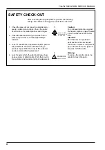
Page 2: ...though functioning show obvious signs of deterioration Point them out to the customer and recommend their replacement 5 Caution For continued protection against fire hazard replace only with same type 2 5 amperes 125 250 volts fuse Attention Afin d assurer une protection permanente contre les risques d incendie remplacer uniquement par un fusible de meme type 2 5 amperes 125 250 volts 6 Warning To...

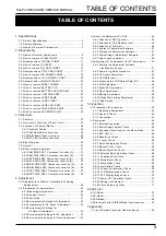
Page 3: ...vironmental Settings for Adjustment 42 4 2 5 Preparations for AF Sensor Adjustment 42 4 2 6 Environmental Settings for AF Sensor Adjustment 42 4 2 7 Environmental settings for AF adjustment 43 4 2 8 Environmental settings for Flash adjustment 43 4 3 About the Adjustment PC Soft 44 4 3 1 Attention at DSC jig driver 44 4 3 2 Attention at PC adjustment soft 45 4 3 3 Attention at Firmware 46 4 3 4 Con...

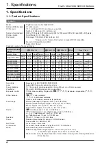
Page 4: ...icrodrive 340MB 19 147 311 765 279 589 566 1119 2729 Approx 307 sec Approx 609 sec Microdrive 1GB 59 443 938 2190 842 1729 1642 3285 8213 Approx 925 sec Approx 1833 sec 1 Specifications 1 1 Product Specifications Sensitivity Equivalent to ISO 160 200 400 800 1600 Lens Super EBC Fujinon 6x optical zoom lens Focus distance f 7 8 mm 46 8 mm Equivalent to 35 mm 210 mm on a 35 mm camera Viewfinder 0 44...

Page 5: ...n x 3 8 in W H D not including accessories and attachments Camera mass weight 500 g 17 6 oz not including accessories batteries or media Weight for photography Approx 600 g 21 2 oz including batteries and SmartMedia Accessories SmartMedia 16MB 3 3V 1 Supplied with Anti static case 1 Index label 1 AA size alkaline batteries 4 Shaulder Strap 1 Protective cover 2 Metal strap clip 2 Clip attaching too...

Page 6: ...tor off Sleep mode to prevent battery depletion and the waste of power when the AC power adapter is connected If the camera is then left unused for a further period the Auto Power Save function switches the camera off This period can be set to 2 minutes or 5 minutes on this camera h The Auto Power Off function does not operate in PC mode during automatic playback or if it is disabled during setup ...

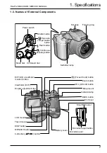
Page 7: ...hutter button Power switch Self timer lamp Hot shoe Focusing ring Strap mount SmartMedia slot Zoom button AE L AE lock button BACK button DISP button Viewfinder EVF Diopter adjustment dial Focus Check button Slot cover MENU OK button 4 direction button Battery cover LCD monitor Indicator lamp EVF LCD viewfinder monitor button Microdrive slot Microdrive eject button Tripod mount ...

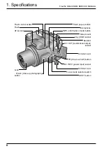
Page 8: ...button SHIFT button USB socket Speaker Microphone A V OUT Audio visual output socket DC IN 5V power input socket Terminal cover Focus mode selector switch Terminal cover INFO information check button Strap mount Lens Macro close up photography button Flash control sensor Flash AF sensor ...

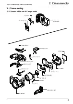
Page 9: ...ly 2 1 Names of Internal Components R CABI ASSY C DIAL UNIT KEY PWB ASSY MAIN PWB ASSY DCST PWB ASSY EVF CONST SPEAKER ASSY TOP CABI ASSY MODE DIAL UNIT AF SENSOR UNIT LCD ASSY ST ASSY CONST CAM PWB ASSY MIC ASSY LENS CONST SIDE MODULE UNIT F CABI ASSY LCD FRAME ...

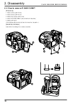
Page 10: ...ocedure 1 Remove screw M1 7x8 0 2 Remove screw M1 7x5 5 3 Remove six screws M1 7x5 0 4 Remove R CABI CONST in the direction of the arrow 5 Remove FFC x2 The undermentioned refer to how to remove the connector Assembly procedure Assemble it according to a reverse procedure 1 2 3 3 3 4 ...

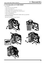
Page 11: ... 2 Remove screw M1 7x4 0 3 Remove C DIAL UNIT in the direction of the arrow 4 Push STRAP L from the direction of the arrow and remove 5 Remove three screws M1 7x4 0 6 Remove KEY PWB ASSY 7 Remove OK BUTTON REAR BUTTON ZOOM BUTTOM and LED LENS Assembly procedure Assemble it according to a reverse procedure 1 2 3 4 6 5 7 7 7 7 ...

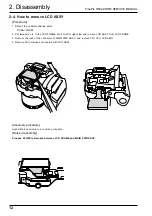
Page 12: ...c in the LCD FRAME hook on LCD right side and remove LCD ASSY from LCD FRAME 3 Remove the lock of the connector of MAIN PWB ASSY and remove FFC from LCD ASSY 4 Remove Wire Harness connected with LCD ASSY Assembly procedure Assemble it according to a reverse procedure Notes of assembly Process FFC Wire Harness between LCD FRAME and MAIN PWB ASSY 1 2 3 ...

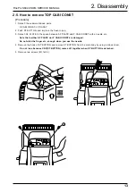
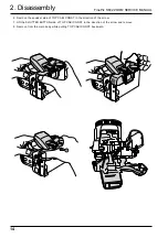
Page 13: ...ach AF PLATE to the space between AF PLATE and F CABI CONST with a needle etc Note that neither AF PLATE nor F CABI CONST are damaged Do not stab the finger etc enough when you use the needle 4 Remove the hook of ST BUTTON and remove ST BUTTON from the main body by using a minus driver Do not lose because CSP ST BUTTON comes off together when ST BUTTON is detached 5 Remove two screws M1 7x5 5 3 4 ...

Page 14: ...ssembly 6 Remove the speaker side of TOP CABI CONST in the direction of the arrow 7 Lift the SHUTTER BUTTON side of TOP CABI CONST in the direction of the arrow and remove 8 Remove from the main body while pulling TOP CABI CONST backward 6 7 8 ...

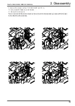
Page 15: ...ire Harness 3 from TOP CABI CONST and FFC 1 10 Pull out SHEET FRAME from LCD FRAME 11 Remove Wire Harness 2 There is no dread of the electric shock and do not touch the terminal when you remove Wire Harness for the flash from the substrate 9 9 9 9 10 11 11 11 10 ...

Page 16: ... side of TOP CABI CONST in intuition in the hook of F CABI CONST 3 Combine the grip part in intuition surely At this time confirm grip rubber is turned over and not transformed 4 Confirm TOP CABI CONST and confirm Wire Harness has been installed after it clings surely in SHEET FRAME 5 Note that it is at the top and bottom The gate is the above in ST BUTTON at assembly 2 3 Note the scissors crowdin...

Page 17: ...2 6 Decomposition of TOP CABI CONST Procedure 1 Remove two screws M1 7x4 0 and remove HOLDER EVF 2 Remove four screws M1 7x4 0 and remove MODE DIAL UNIT 3 Remove EVF CONST 4 Remove SPEAKER ASSY 5 Remove two screws M1 7x4 0 and remove ST TOP 1 2 3 4 5 5 ...

Page 18: ... remove Assembly procedure Assemble it according to a reverse procedure Notes of assembly Note the taking turning of the flash hiss harness Pass the flash hiss harness and the flash harness through the fingernail of HOLDER EVF Do not float on the flash hiss harness and the flash harness harness do not interfere in flash pop up detection SW Flash pop up detection SW ...

Page 19: ...ure 1 Detach the undermentioned parts R CABI CONST LCD ASSY ST PLATE ST BUTTON TOP CABI CONST 2 Remove FFC Wire Haness 4 2 3 Remove main body A and part B and remove LCD FRAME CONST 4 Discharge electricity from the main capacitor of DCST PWB ASSY Assembly procedure Assemble it according to a reverse procedure ...

Page 20: ...ork is started 1 Remove two screws M1 7x3 0 and remove CONTACT PLT and DCST PWB ASSY 2 Remove two screws M1 7x3 0 and remove MAIN PWB ASSY Assembly procedure Assemble it according to a reverse procedure 2 9 Decomposition of MAIN PWB ASY Procedure 1 Remove EJECTER in the direction of the arrow 2 Remove SHEET CF Assembly procedure Assemble it according to a reverse procedure 1 2 1 2 ...

Page 21: ... FRAME Assembly procedure Assemble it according to a reverse procedure Notes of assembly Note the damage of SHEET FRAME when you install SHEET FRAME in LCD FRAME 2 11 How to remove BATTERY LID Procedure 1 Lift the hook of BATTERY LID and remove BATTERY LID Assembly procedure Assemble it according to a reverse procedure 2 ...

Page 22: ...in body while opening the main body grip part Assembly procedure Assemble it according to a reverse procedure 2 13 How to remove CAM PWB ASSY Procedure 1 Detach the undermentioned parts R CABI CONST LCD ASSY ST PLATE ST BUTTON TOP CABI CONST LCD FRAME CONST 2 Open the hook of LENS FRAME and remove CAM PWB ASSY in the direction of the arrow 3 Remove FPC from LENS CONST and remove CAM PWB ASSY from ...

Page 23: ...ve screw M1 7x5 0 and remove LENS FRAME from the main body Assembly procedure Assemble it according to a reverse procedure Notes of assembly Do so as not to cut FFC adding impossible power when you build FFC into LENS FRAME noting it 2 15 How to remove LENS CONST Procedure 1 Detach the undermentioned parts R CABI CONST LCD ASSY ST PLATE ST BUTTON TOP CABI CONST LCD FRAME CONST BATTERY LID BATTERY ...

Page 24: ...E LENS CONST 2 Remove three screws M1 7X3 5 and remove LENS CABI ASSY Assembly procedure Assemble it according to a reverse procedure Attention Because the torque is managed as for FOCUS RING of LENS CABI ASSY it is not possible to decompose 2 Assembly procedure Assemble it according to a reverse procedure Notes of assembly Make the cutting lack of the rib and LENS CONST of F CABI CONST combined i...

Page 25: ...ST LCD FRAME CONST BATTERY LID BATTERY HOLDER UNIT CAM PWB ASSY LENS FRAME LENS CONST LENS CABI ASSY 2 Remove screw M1 7x5 0 and remove STRAP R 3 Remove SIDE MODILE UNIT from F CABI ASSY 2 3 Assembly procedure Assemble it according to a reverse procedure Notes of assembly Match and build in the position of the FOCUS switch lever of FOCUS switch SW and F CABI ASSY of SIDE MODILE UNIT ...

Page 26: ...RY LID BATTERY HOLDER UNIT CAM PWB ASSY LENS FRAME LENS CONST LENS CABI ASSY 2 Remove AF SENSOR UNIT in the direction of the arrow while pushing the front side part of AF SENSOR UNIT by the finger Assembly procedure Assemble it according to a reverse procedure Attention Replace F CABI ASSY when guide ditch part F CABI ASSY is damaged when AF SENSOR UNIT is detached 2 AF SENSOR UNIT ࠟࠗ Ḵㇱ Guide dit...

Page 27: ...tions of Each Circuit Board Name Block name Function LENS CONST CCD BLOCK CCD output CAM PWB ASSY CAM BLOCK Analog to digital conversion of CCD output IC102 CCD driver IC100 MAIN PWB ASSY PROCESS BLOCK Video signal processing IC210 USB communication IC210 System control IC210 MOTOR BLOCK Shutter Iris AF Zoom driver IC602 POWER ON BLOCK Power control IC302 EVF BLOCK EVF control IC405 LCD BLOCK LCD ...

Page 28: ...bit 16 bit x 2 data The 32 bit image data is then sent from the I O Buffer in UCS1_IC and stored in the SDRAM_IC IC211 IC218 IC219 40 Mbyte A single frame 2832 pixels x 2128 lines of image data is temporarily stored in the SDRAM_IC At the same time AE multiplies the 12 bit image data input from the UCS1_IC in AUTO and sends the data required for AE AWB AF to the SDRAM_IC To provide the appropriate...

Page 29: ... I F IBUF TFDC IMAGE BUS 32bit 75MHz BITMAP CG D A 4ch MADIA JPEG ENCD USB SIO WDT MFT ICU ADC PORT CLKC CPU BUS 32bit 75MHz MICON I O BUS 32bit 75MHz CPU CORE SDI SDRAM 32KB I cache 8KB BUS CONTROL MICON CORE A D I O BUFFER IMAGE BUS I F UCS1 IC210 CSP 12 AF SENSOR R G B MIC_AMP LPF 75 ohm Drv LED_BL EVF_BL SSFDC CF MD SOCKET EVF CONT IC405 LCD CONT IC404 VBS AV_DET X TAL 24 5MHz X TAL 48MHz LED ...

Page 30: ... SSFDC CONNECTOR CN206 CF CONNECTOR CN207 USB JACK AV JACK MIC CN500 SPEAKER CN501 KEY PWB ASSY CN203 CN204 AF SENSOR UNIT SIDE MODULE UNIT F P C B to B CN903 CN902 DCST PWB ASSY LCD_BL LCD Monitor F P C EVF_BL EVF Monitor CN401 CN400 CN800 CN904 CN1001 CN1000 CN901 CN900 LENS CONST F P C CN1201 MODE DIAL UNIT F P C CN1202 C DIAL UNIT BATTERY HOLDER DC JACK HOT SHOE CDS TRIGER Xe ...

Page 31: ......

Page 32: ......

Page 33: ......

Page 34: ......

Page 35: ......

Page 36: ......

Page 37: ......

Page 38: ......

Page 39: ...OM IC212 3 The camera will remain in the Jig mode unless the final settings are entered Always enter the final settings after adjustment is complete 4 Irrespective of whether or not components have been replaced if the two screws M1 7 x 5 5 holding the AF sensor in place are removed the AF sensor will be displaced horizontally and vertically in relation to the lens and AF Sensor Adjustment is ther...

Page 40: ... VTR Note 2 Lens Holder ZJ00008 100 AF Common with 8mm VTR Note 2 Lens Stand ZJ00009 100 AF Common with 8mm VTR Note 2 Lens Base Plate ZJ00010 100 AF Common with 8mm VTR Note 2 f 900mm Conversion Lens ZJ00287 100 AF Sensor Common with 8mm VTR Note 2 AF Sensor Adjustment Chart 700mm ZJ00542 100 AF Sensor Chart only for 700mm adjustment AF Sensor Adjustment Chart 1000mm ZJ00543 100 AF Sensor Chart o...

Page 41: ... Fig 2 1 Connection USB Cable PC FinePix S602Zoom Stabilized Power Supply Power Cable Jig TV Monitor Video Cable Conversion lens complete set Lens Holder Lens Base Plate Lens Stand Attention when conversion lens is used Convex side Subject side Plane Camera lens side ...

Page 42: ...he TV monitor 7 Place a mark in the center of the target mark displayed on the TV monitor 8 Draw a circle on the OHP sheet with the marked point as the center The size of the circle will differ from the TV monitor used The circle sizes for the various TV monitors are as follows 14 to 16 5mm radius 17 to 19 6mm radius 20 to 21 7mm radius 9 This completes preparations for AF Sensor Adjustment 4 2 6 ...

Page 43: ...ing if the center of conversion lens and the center of the camera lens come off largely and it is set and it cannot AF adjustment FinePix S602 40mm 5mm TV Monitor PC Siemens star chart Light Fluorescent lamp stand INF Adjustment 640mm 5mm with f 600mm conversion lens 900mm Adjustment 940mm 5mm 500mm Adjustment 540mm 5mm 100mm Adjustment 140mm 5mm 4 2 8 Environmental settings for Flash adjustment 1...

Page 44: ... fujifilm di intranets com 2 Defrost the downloaded compression file Note The DSC jig driver in this server is compression file of ZIP form Therefore after downloading this compression file from the Web server the decompression of the file is neces sary In the decompression software if the decompression of the ZIP form can be done any software is OK Please prepare each one for the decompression so...

Page 45: ...re is different in each model the compression file name is also different Specify the preservation drive for C drive if it is decompression software which can specify the preservation drive Similarly defrost without making a new folder if it is decompression software that can be defrosted without making a new folder Defrost simply if the decompression software which you cannot specify the drive sp...

Page 46: ...mpression and the preservation method of the firmware are described as an example of FinePix2300 Firmware in this server is compression file of ZIP form Therefore after downloading this compression file from the Web server the decompression of the file is neces sary In the decompression software if the decompression of the ZIP form can be done any software is OK Please prepare each one for the dec...

Page 47: ...ttery voltage adjustment F2 Mode dial voltage adjustment F4 CCD data input F5 CAM adjustment F6 Zoom AF adjustment F7 Flash adjustment F11 AF sensor adjustment F12 End setting 4 3 5 Starting the Adjustment Software 1 Double click on FFW exe in the FinePix S602 folder previously copied to the C drive 2 The FFW exe 0 dialog box appears on the screen see Fig 1 3 See the next page for details of custo...

Page 48: ...alog box select Compile 3 Click the Select User Program button then select the file FxS602Z ff 4 Click the Select Editor button then select Write exe 2 EVR Procedure Fig 3 13 1 Select EVR from the Customize dialog box 2 Conditions etc V2 Check LANC page check Check 3 Hardware Procedure Fig 3 14 1 Select Hardware from the Customize dialog box 2 Conditions Etc 7 Segment 7 Debug Mode Ignore Focus I O...

Page 49: ...rt FFW exe After adjustments are completed turn the camera s power switch Off and finish with the adjustments If the NG message appears and you stop the program during the PC adjustments turn the camera s power switch OFF one time then carry out the adjustment again 4 Other Procedure Fig 3 15 1 Select Other from the Customize dialog box 2 Select the Other Conditions setting 3 Conditions Auto measu...

Page 50: ...ser program ff Use this when it is necessary to edit the user program Data ad Do not use this command rd Do not use this command SW Do not use this command fsw Do not use this command EVR Do not use this command Mode File Recording Do not use this command NGSTOP Stops the program if an adjustment is NG STEP Do not use this command LINE Do not use this command AUTO Do not use this command Setting O...

Page 51: ... The content of the adjustment is different because of replaced parts 2 Refer to the service manual for the adjustment done after parts are replaced 3 Use Power supply cable jig at all the adjustments 4 Execute the end setting when using this adjustment software 5 Notes have been described to the service manual besides the above mentioned and advance the adjustment after it refers Advance to the j...

Page 52: ...ance of the chart 6 When the surface reflective luminance of the chart has been measured make the adjustment preparations 2 in accordance with the instructions from the adjustment software Adjust the screen angle so that the symbol red displayed on the TV monitor is within the circle 7 When preparations are complete press the Enter key on the PC to begin AF Sensor Adjustment 1000mm 8 Adjust the AF...

Page 53: ...nt is complete terminate AF Sensor Adjustment Press the Enter key on the PC to return to the Adjustment Items Select Screen Position of AF Sensor Adjustment Screw AF ࡦࠨ ᢛߨߓ Fig 8 Adjustment Preparation 900mm Screen Fig 9 AF Sensor Left Right Difference Adjustment Preparations Screen Fig 10 AF Sensor Adjustment complete Screen Fig 7 WAVE No 0 Dialog Box OK Screen Fig 6 AF Sensor Adjustment Screen A...

Page 54: ...ectly press the Enter key on the PC to return to the Adjustment Items Select Screen Fig 12 CCD Data Input Start Screen Fig 14 CCD Data Input Screen Fig 13 CCD Data Input Dialog Box Screen Fig 11 Adjustment Items Select Menu Screen Fig 15 CCD Data Input complete Screen FxS602Z ff CCD data input complete Press the Enter key return to the menu screen FxS602Z ff All pixels defect data processing Defec...

Page 55: ... ie defect data for another CCD will be used 2 Download the ZIP file of top four digits from Web server http fujifilm di intranets com Open ZJ00535 100 Fig 17 1 in the CCD defect data folder and download 1484 zip Fig 17 2 3 Decompress 1484 zip 1484 folders including 14840750 dat is made 4 Insert a writable floppy disk into the floppy disk drive on the computer 5 Open in 1484 folders search for 148...

Page 56: ...the instructions from the adjustment software 5 When CAM adjustment is complete press the Enter key on the PC to return to the Adjustment Items Select Screen Fig 21 CAM Adjustment Complete Screen Fig 18 Adjustment Items Select Menu Screen Fig 19 CAM Adjustment Preparation Screen Fig 20 LB140 Filter Preparations Screen FxS602Z ff CAM adjustment complete Press the Enter key return to the menu screen...

Page 57: ...tive luminance of Siemens star chart 8 0Ev to 10 0Ev 4 When the setup necessary for AF adjustment is complete press the Enter key on the PC to begin AF adjust ment Perform AF adjustment in accordance with the instructions from the adjustment software 5 When Zoom AF adjustment is completed normally press the Enter key on the PC to return to the Adjustment Items Select Screen Fig 25 Zoom AF Adjustme...

Page 58: ...ment is complete press the Enter key on the PC to begin flash adjustment Perform flash adjustment in accordance with the instructions from the adjustment software 6 When flash adjustment is completed normally press the Enter key on the PC to return to the Adjustment Items Select Screen Fig 29 Flash Adjustment Complete Screen Fig 27 Flash Adjustment Preparations Screen Fig 26 Adjustment Items Selec...

Page 59: ...e DC IN jack 6 When the input voltage has been set press the Enter key on the PC to write the adjusted value 7 When battery adjustment is completed normally press the Enter key on the PC to return to the Adjustment Items Select Screen Adjustment address Data limits P4 E3 BATT_PREEND 65h 85h E4 BATT_END 5Fh 7Fh Fig 32 Battery End Adjustment Start Screen Fig 30 Adjustment Items Select Menu Screen Fi...

Page 60: ...Fig 37 Mode Dial Adjustment Complete Screen Fig 34 Adjustment Items Select Menu Screen Fig 36 Adjustment Value Measurement Screen Fig 35 Mode Dial Adjustment Start Screen Adjustment address Data limits P4 E5 MODE D1h F1h FxS602Z ff Mode dial voltage adjustment complete Press the Enter key return to the menu screen FxS602Z ff Mode dial voltage adjustment 1 The mode dial is SET UP position 2 Input 5...

Page 61: ... the camera in the camera Jig mode again to make further adjustments Fig 39 USB ID Entry Screen Fig 41 Adjustment Complete Screen Fig 38 Adjustment Items Select Screen Fig 40 Repair base ID Entry Screen FxS602Z ff FinePix S602 Zoom PC adjustment software Adjustment items select menu F1 Battery voltage adjustment F2 Mode dial voltage adjustment F4 CCD data input F5 CAM adjustment F6 Zoom AF adjustm...

Page 62: ...ent Color meter COLOR METER 3F Made by Minolta or equivalent 5 1 2 Jigs and Charts Product Model Parts No Remarks Micro drive with image ZJ00397 100 LCD EVF inspection Note 1 Gray Chart ZJ00254 100 Flash inspection Inspection Chart ZJ00540 100 Resolution inspection Power Cable Jig ZJ00213 100 General inspection AC Adaptor AC 5V General inspection Accessories USB Cable General inspection Accessorie...

Page 63: ... S602 ZOOM SERVICE MANUAL 5 Inspection 63 5 1 3 Connection Fig 5 1 Connection FinePix S602 Zoom Power Cable Jig VIDEO Cable Vector Monitor Waveform Monitor TV Monitor Ammeter Voltmeter Stabilized Power Supply ...

Page 64: ...Check that the date etc is displayed on the LCD monitor for approxi mately two seconds Date format differs with region J YYYY MM DD U MM DD YYYY E EG DD MM YYYY 5 2 3 Checking Shock Noise in the Movie Mode Procedure and Checks 1 Apply an appropriate shock to the camera Do not apply a shock directly to the lens or card cover Check for problems with the LCD monitor Check that the camera recovers fro...

Page 65: ...oto Check that the indicator lamp blinks green and then changes to orange Check that the shutter sound is heard 7 Set the camera power lever to the Playback mode Check that the photographed resolution inspection chart is dis played 8 Check the resolution on the TV monitor Center Minimum of 350 lines on monitor Periphery Minimum of 300 lines on monitor Caution The resolution values noted here are n...

Page 66: ...or the Y level check Recording pixels VGA 640 x 480 Photography mode M WB Electric bulb mode Flash OFF AF MF selector switch MF 4 Press the release button to take a photo Check that the indicator lamp blinks green and then changes to orange Check that the shutter sound is heard 5 Set the camera power lever to the Playback mode Check that the photographed image is displayed 6 Check the Y level usin...

Page 67: ...orange Check that the shutter sound is heard Check that the flash is lit 4 Retract the flash Check that the flash symbol disappears 5 Set the camera power lever to the Playback mode Check that the photographed gray chart is displayed 6 Check the light adjustment level and WB using the waveform monitor and vector scope Light adjustment level Waveform monitor 49 12IRE Waveform Monitor Vector scope ࡌ...

Page 68: ...ress the menu button to return to the internal flash mode 5 2 11 Command Dial Check Procedure and Checks 1 Turn the command dial left right Check that the F value at bottom left of the LCD monitor changes 5 2 12 Movie Audio Check Procedure and Checks 1 Set the mode dial to the movie photography mode Check that Standby is displayed on the LCD monitor 2 Press the release button to begin movie photog...

Page 69: ...and playback completely black Check that there is no noticeable dust or contamination eg lumines cent spots on the LCD monitor screen 2 Playback completely white 75 Check that there is no noticeable dust or contamination eg uneven ness dropout spots on the LCD monitor screen Ṍὐⷙᩰ 1 4 H 1 2 1 4 1 4 1 2 1 4 V A B ࡦ ࡦ ว ᐔᣇะㅪ Ṍὐ એ ή߈ߎߣ ု ᣇะㅪ Ṍὐ ή߈ߎߣ Ṍὐ㑆 㔌 OOએ A zone 3 B zone 4 Total 7 Maximum number o...

Page 70: ...select the brightness and then press the left right key Check that brightness changes on the EVF monitor 5 2 18 Power OFF Operation Check Procedure and Checks 1 Set the camera power lever to the Photography mode and set the mode dial to SETUP 2 Press the bottom of the four keys to select full reset and press the MENU OK button 3 Set the camera power lever to OFF Check that the lens retracts 8 ノὐⷙᩰ...

Page 71: ...2 20 Clock Setup and Clear Procedure and Checks 1 Connect the USB cable between the PC and the camera Check that the PC is switched ON 2 Open the card cover and with the release button pressed switch power ON 3 Set the camera power lever to OFF No operation is needed at the PC 4 Remove the USB cable and connect it again 5 Close the card cover and set the camera power lever to the Playback mode Che...

Page 72: ...0 200 I F MANUAL ENGLISH A108 BL00135 200 OWNERS MANUAL ENGLISH A109 BB07792 101 WARRANTY US A110 FZ03529 200 USB CABLE A111 FZ04741 100 VIDEO CABLE A112 FZ04403 101 CD ROM A113 BB11327 100 SSFDC LABEL A114 BF02317 200 SSFDC ASSY 16MB A115 BB04598 400 SSFDC DUST COVER A116 BL00162 100 QUICK START GUIDE A117 BL00187 100 INFO PAPER MOVIE A118 BB12402 100 LENSCAP HOLDER A119 BU02578 100 SHOULDER BELT...

Page 73: ...FZ04691 100 SIDE MODULE UNIT M206 UBFZZ0020A DC JACK COVER M207 BB13205 100 STRAP R M208 BB13148 200 SCREW M1 7X5 0BC x1 M209 BU02572 100 LENS CONST M210 BB13149 200 SCREW M1 7X5 0BC GN x5 M211 BB13201 100 LENS FRAME M212 CB0892 A100 CAM PWB ASSY M213 CB0895 A101 MC PWB ASSY MAIN CAM M214 FZ04692 100 BATT HOLDER UNIT M215 BU01959 100 BATTERY LID ASSY M216 FZ04693 100 AF SENSOR UNIT M214 M210 M211 ...

Page 74: ...ING TUBE M310 BB13183 100 CONTACT PLT M311 BF03968 100 LCD ASSY 1 8inch M312 BB13182 100 SHEET FRAME M313 FZ04701 100 WIRE HARNESS DCST LCD M314 BU01955 100 TOP CABI ASSY ABS M315 BU02573 100 ST ASSY CONST M316 BB11621 100 ST SHAFT M317 BB13193 200 ST TOP U M318 BB13149 100 SCREW M1 7X4 0BC GN x8 M319 FZ04694 100 MODE DIAL UNIT M320 BU02571 100 EVF CONST M321 BB13204 100 HOLDER EVF M322 FZ04695 10...

Page 75: ...ASSY ABS M402 BB13187 100 LCD CUSHION M403 BB13170 100 ZOOM BUTTON M404 BB13172 100 REAR BUTTON M405 BB13174 100 LED LENS M406 BB13178 100 SHEET SW M407 BB13169 100 OK BUTTON M408 CB0893 A101 KEY PWB ASSY M409 BB13149 100 SCREW M1 7X4 0BC GN x4 M410 BB13206 100 STRAP L M411 FZ04696 101 C DIAL UNIT M401 M403 M406 M402 M405 M404 M411 M410 N S M409 M409 M408 M407 ...

Page 76: ...CREW M1 7X5 0BC x6 M502 BB13148 300 SCREW M1 7X8 0BC x1 M503 BB13149 300 SCREW M1 7X5 5BC GN x1 M504 BB13134 100 ST BUTTON M505 BB13160 100 CSP ST BUTTON M506 BB13208 100 LCD WINDOW M507 BB13212 100 AF PLATE M508 BB10000 200 CCD BADGE S U M509 BB13211 200 PRODUCT LABEL M510 BB09250 200 PL SEAL U M507 M502 M503 M501 M506 M501 M505 M504 M509 M510 M501 M508 ...

Page 77: ...BLE A109 FZ04741 100 VIDEO CABLE A110 FZ04403 101 CD ROM A111 BB11327 100 SSFDC LABEL A112 BF02317 200 SSFDC ASSY 16MB A113 BB04598 400 SSFDC DUST COVER A114 BL00120 300 I F MANUAL FRENCH A115 BL00120 400 I F MANUAL GERMAN A116 BL00135 300 OWNERS MANUAL FRENCH A117 BL00135 400 OWNERS MANUAL GERMAN A118 BL00162 100 QUICK START GUIDE A119 BL00187 100 INFO PAPER MOVIE A120 BB12402 100 LENSCAP HOLDER ...

Page 78: ...FZ04691 100 SIDE MODULE UNIT M206 UBFZZ0020A DC JACK COVER M207 BB13205 100 STRAP R M208 BB13148 200 SCREW M1 7X5 0BC x1 M209 BU02572 100 LENS CONST M210 BB13149 200 SCREW M1 7X5 0BC GN x5 M211 BB13201 100 LENS FRAME M212 CB0892 A100 CAM PWB ASSY M213 CB0895 A101 MC PWB ASSY MAIN CAM M214 FZ04692 100 BATT HOLDER UNIT M215 BU01959 100 BATTERY LID ASSY M216 FZ04693 100 AF SENSOR UNIT M214 M210 M211 ...

Page 79: ...ING TUBE M310 BB13183 100 CONTACT PLT M311 BF03968 100 LCD ASSY 1 8inch M312 BB13182 100 SHEET FRAME M313 FZ04701 100 WIRE HARNESS DCST LCD M314 BU01955 100 TOP CABI ASSY ABS M315 BU02573 100 ST ASSY CONST M316 BB11621 100 ST SHAFT M317 BB13193 200 ST TOP U M318 BB13149 100 SCREW M1 7X4 0BC GN x8 M319 FZ04694 100 MODE DIAL UNIT M320 BU02571 100 EVF CONST M321 BB13204 100 HOLDER EVF M322 FZ04695 10...

Page 80: ...ASSY ABS M402 BB13187 100 LCD CUSHION M403 BB13170 100 ZOOM BUTTON M404 BB13172 100 REAR BUTTON M405 BB13174 100 LED LENS M406 BB13178 100 SHEET SW M407 BB13169 100 OK BUTTON M408 CB0893 A101 KEY PWB ASSY M409 BB13149 100 SCREW M1 7X4 0BC GN x4 M410 BB13206 100 STRAP L M411 FZ04696 101 C DIAL UNIT M401 M403 M406 M402 M405 M404 M411 M410 N S M409 M409 M408 M407 ...

Page 81: ...01 BB13148 200 SCREW M1 7X5 0BC x6 M502 BB13148 300 SCREW M1 7X8 0BC x1 M503 BB13149 300 SCREW M1 7X5 5BC GN x1 M504 BB13134 100 ST BUTTON M505 BB13160 100 CSP ST BUTTON M506 BB13208 100 LCD WINDOW M507 BB13212 100 AF PLATE M508 BB10000 200 CCD BADGE S U M509 BB13211 200 PRODUCT LABEL M507 M502 M503 M501 M506 M501 M505 M504 M509 M501 M508 ...

Page 82: ...00 I F MANUAL ENGLISH A107 BL00135 200 OWNERS MANUAL ENGLISH A108 FZ03529 200 USB CABLE A109 FZ04741 100 VIDEO CABLE A110 FZ04403 101 CD ROM A111 BB11327 100 SSFDC LABEL A112 BF02317 200 SSFDC ASSY 16MB A113 BB04598 400 SSFDC DUST COVER A114 BL00162 100 QUICK START GUIDE A115 BL00187 100 INFO PAPER MOVIE A116 BB12402 100 LENSCAP HOLDER A117 BU02578 100 SHOULDER BELT ASSY A118 BU01815 300 LENS CAP ...

Page 83: ...FZ04691 100 SIDE MODULE UNIT M206 UBFZZ0020A DC JACK COVER M207 BB13205 100 STRAP R M208 BB13148 200 SCREW M1 7X5 0BC x1 M209 BU02572 100 LENS CONST M210 BB13149 200 SCREW M1 7X5 0BC GN x5 M211 BB13201 100 LENS FRAME M212 CB0892 A100 CAM PWB ASSY M213 CB0895 A101 MC PWB ASSY MAIN CAM M214 FZ04692 100 BATT HOLDER UNIT M215 BU01959 100 BATTERY LID ASSY M216 FZ04693 100 AF SENSOR UNIT M214 M210 M211 ...

Page 84: ...ATING TUBE M310 BB13183 100 CONTACT PLT M311 BF03968 100 LCD ASSY 1 8inch M312 BB13182 100 SHEET FRAME M313 FZ04701 100 WIRE HARNESS DCST LCD M314 BU01955 100 TOP CABI ASSY ABS M315 BU02573 100 ST ASSY CONST M316 BB11621 100 ST SHAFT M317 BB13193 200 ST TOP U M318 BB13149 100 SCREW M1 7X4 0BC GN x8 M319 FZ04694 100 MODE DIAL UNIT M320 BU02571 100 EVF CONST M321 BB13204 100 HOLDER EVF M322 FZ04695 ...

Page 85: ... ASSY ABS M402 BB13187 100 LCD CUSHION M403 BB13170 100 ZOOM BUTTON M404 BB13172 100 REAR BUTTON M405 BB13174 100 LED LENS M406 BB13178 100 SHEET SW M407 BB13169 100 OK BUTTON M408 CB0893 A101 KEY PWB ASSY M409 BB13149 100 SCREW M1 7X4 0BC GN x4 M410 BB13206 100 STRAP L M411 FZ04696 101 C DIAL UNIT M401 M403 M406 M402 M405 M404 M411 M410 N S M409 M409 M408 M407 ...

Page 86: ...01 BB13148 200 SCREW M1 7X5 0BC x6 M502 BB13148 300 SCREW M1 7X8 0BC x1 M503 BB13149 300 SCREW M1 7X5 5BC GN x1 M504 BB13134 100 ST BUTTON M505 BB13160 100 CSP ST BUTTON M506 BB13208 100 LCD WINDOW M507 BB13212 100 AF PLATE M508 BB10000 200 CCD BADGE S U M509 BB13211 200 PRODUCT LABEL M507 M502 M503 M501 M506 M501 M505 M504 M509 M501 M508 ...

Page 87: ...NECTOR CJ 24P FN 0 5MM NH CN800 FGC125 0701 CONNECTOR CJ 70P BN 0 5MM PV JACK CN205 FZ03803 100 JACK USB J700 FZ04344 100 JACK VIDEO FUSE F300 FP00036 502 FUSE 0 5A 32V UL DCST PWB ASSY CONNECTOR CN1000 FGA157 0041 CONNECTOR LJ 4P SN 2 0MM RV CN1001 FGA058 0021 CONNECTOR CJ 2P RN 1 25MM PN CN900 FGA113 0021 CONNECTOR CJ 2P RN 1 5MM PH CN901 FGA113 0021 CONNECTOR CJ 2P RN 1 5MM PH CN902 FGA155 0021...

Page 88: ...NUAL 88 7 Appendix 7 1 List of Related Technical Updates Issued To ensure that after sales srevice is performed accuratety keep a record here of the technical updates issued that cover this device Technical Update No Date Title Details Other ...

Page 89: ...26 30 Nishiazabu 2 chome Minato ku Tokyo 106 8620 Japan FUJI PHOTO FILM CO LTD ...

Reviews: