background image

1U030584

READ AND SAVE THESE INSTRUCTIONS.

Keep this manual in a convenient place for future reference.

FUJI INDUSTRIAL CO., LTD.

TABLE OF CONTENTS

Safety Instructions .................................................................................................. 2
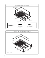
Name of Parts ......................................................................................................... 4
Size & Dimensions .................................................................................................. 4
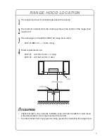
Range Hood Location ............................................................................................. 5
Installation ............................................................................................................... 6

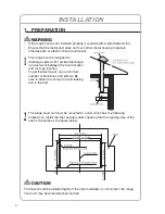
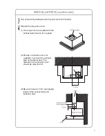
1. Preparation ..................................................................................................... 6
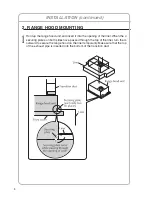
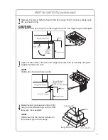
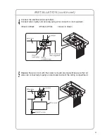
2. Range Hood Mounting .................................................................................... 8
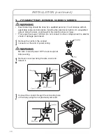
3. Connecting Power Supply Wires ................................................................... 10
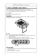
4. Final Assembly and Check ............................................................................ 12
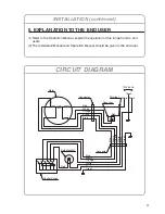
5. Explanation to the End User ......................................................................... 13

Circuit Diagram ..................................................................................................... 13

Installation Manual
RANGE HOOD

MODEL:BUF-01

BUF-02

Summary of Contents for BUF-01

Page 1: ...LTD TABLE OF CONTENTS Safety Instructions 2 Name of Parts 4 Size Dimensions 4 Range Hood Location 5 Installation 6 1 Preparation 6 2 Range Hood Mounting 8 3 Connecting Power Supply Wires 10 4 Final Assembly and Check 12 5 Explanation to the End User 13 Circuit Diagram 13 Installation Manual RANGE HOOD MODEL BUF 01 BUF 02 ...

Page 2: ...ly When the service disconnecting means cannot be locked securely fasten a prominent warning device such as a tag to the service panel 2 To reduce the risk of fire or electric shock do not use this product with any solid state speed control device 3 TO REDUCE THE RISK OF FIRE ELECTRIC SHOCK OR INJURY TO PERSONS OBSERVE THE FOLLOWING a Installation work and electrical wiring must be done by a quali...

Page 3: ... Do not vent exhaust air into spaces within walls ceilings or into attics crawl spaces or garages 6 Fasten the filter and other parts securely Incorrect attachment may result in personal injury or property damage 4 Use only for the purpose of kitchen ventilation 1 For general ventilating use only Do not use to exhaust hazardous or explosive material and vapors 7 Keep your hands and other objects a...

Page 4: ...4 NAME OF PARTS SIZE DIMENSIONS Unit inch Accessories Accessories Accessories Accessories Accessories Screw M5 30 Four 4 pieces Nut with plate Four 4 pieces ...

Page 5: ...01 BUF 02 range hood unit is BUF 01 BUF 02 18 lbs 8 kg 4 Power requirements are BUF 01 AC120 V 60 Hz 1 3 Amp BUF 02 AC120 V 60 Hz 2 Amp RANGE HOOD LOCATION CAUTION Check that the hood is correctly installed since incorrect installation could result in the detachment of the range hood and the unit fall To protect hands from injury wear working gloves when installing the range hood ...

Page 6: ...n the hood location and roof cap location To get the best result use a minimum number of transitions and elbows Be sure to attach a roof cap to avoid leaking rain in the end 2 The range hood unit must be mounted to a liner which has the following dimensions Install the liner securely after checking that the opening size of the liner is the same as the figure below INSTALLATION CAUTION The liner sh...

Page 7: ...d unit 1 The range hood is supplied with the exhaust pipe fixed on its top plate 2 Provide a transition duct not supplied to connect the exhaust pipe and external duct The diameter of the transition duct should be more than 6 3 Be sure to keep 1 3 16 overlapping length of the exhaust pipe and transition duct ...

Page 8: ...ing of the liner When the 4 securing plates on both sides have passed through the top of the liner turn them outward to secure the range hood on the liner temporarily Make sure that the top of the exhaust pipe is inserted into the bottom of the transition duct INSTALLATION continued ...

Page 9: ...the range hood unit The hinge may be damaged 3 Align 4 screw holes of the liner and range hood unit then fix securely using the supplied screws and nuts NOTE Fasten all screws and nuts evenly 4 Make the duct joint secure and air tight using non flammable tape such as duct tape etc not supplied NOTE Make sure that the shutter installed in the exhaust pipe moves freely ...

Page 10: ... electric shock or injury This range hood uses 120V AC Do not connect to other voltage since fire electric shock or damage could result 1 Remove the nut from the conduit connector at the end of power wiring WARNING Be sure to switch power OFF at service panel before wiring 2 Remove one screw fixing the wire cover and detach it 3 Connect the conduit through the connecting hole of the body using the...

Page 11: ... Connect wires tightly and securely using wire connectors not supplied Black to Black White to White Green to Green 5 Replace the wire cover with the screw removed previously Make sure that all wires are connected properly and enclosed inside of the wiring compartment ...

Page 12: ...e sure to tighten the screws with the torque of 13 inch lbs 1 5 N m or less 2 Check 1 Turn on the electrical circuit to the range hood 2 Make sure that the switch and light operate correctly Refer to page 4 of the Operation Manual 3 Check the ventilating functions at Hi Me and Lo positions 4 Make sure that the range hood has no abnormal noises and or vibration INSTALLATION continued CAUTION To red...

Page 13: ...The Installation Manual and Operation Manual should be given to the end user INSTALLATION continued CIRCUIT DIAGRAM Motor Connector Connector Terminal Capacitor Red Red Red White White Orange Brown Blue White Orange Brown Blue Green Green Black Black White Orange Brown Blue Green Black 120V 60Hz Bulb Max40W Control Switch ...

Page 14: ...Fuji Industrial USA Inc 16300 Christensen Rd Ste 212 Seattle WA 98188 3403 Telephone 1 888 547 9880 1U030584 ...

Reviews: