
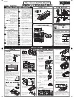
Bulb
(Not supplied)
Fan Switch
(Right)
Fan Switch
(Left)
Front Cover
Enclosure
Filter
Lamp Switch
Lamp Switch
High Switch
Medium Switch
Low Switch
OFF Switch
Pilot Lamp
Lamp (Not supplied)
(PAR20 bulb, in the base
diameter 26mm:
medium base)
INSTALLATION MANUAL
Model: BUF-08W
Before installation and operation, read these instructions carefully
and use this product only in the manner described by the
manufacturer in the operation manual.
The instruction shown below are used to alert you to potential
personal injury and property damage hazards.
There are three hazard classifications based on potentially
dangerous situations.
Obey all safety instructions that show these symbols to avoid
possible injury, death and property damage.
SAFETY INSTRUCTIONS
WARNING:
WARNING indicates a potentially
hazardous situation which, if not
avoided, could result in death or
serious injury.
CAUTION:
CAUTION indicates a potentially
hazardous situation which, if not
avoided, may result in minor or
moderate injury.
NOTE
: The safety instructions are explained with the following
pictographic symbols.
means forcible execution. It indicates actions, if
any, that must be done.
WARNING
1. TO REDUCE THE RISK OF FIRE, ELECTRIC
SHOCK, OR INJURY TO PERSONS, OBSERVE
THE FOLLOWING:
a) Use this unit only in the manner intended by the
manufacturer. If you have questions, contact the
manufacturer.
b) Before servicing or cleaning the unit, switch power
off at service panel and lock the service
disconnecting means to prevent power from being
switched on accidentally. When the service
disconnecting means cannot be locked, securely
fasten a prominent warning device, such as a tag,
to the service panel.
CAUTION
INSTALLATION
1. Preparation
2. Range Hood Mounting
3. Connecting Power Supply Wires
1
Remove the nut from the conduit
connector at the end of power wiring.
2
Remove one screw fixing
the wire cover then slide it
to detach.
4. Final Assembly and Check
(6) Three 50 Watt halogen light bulbs (not supplied)
can be mounted in this range hood.
Range Hood
3. Read specification label on this product for further
information and requirements.
2. To reduce the risk of fire and to properly exhaust
air, be sure to duct air outside. Do not vent exhaust
air into spaces within walls, ceilings or into attics,
crawl spaces or garages.
6. Fasten the filter and other parts securely. Incorrect
attachment may result in personal injury or
property damage.
4. Use only for the purpose of kitchen ventilation.
1. For general ventilating use only. Do not use to
exhaust hazardous or explosive material and
vapors.
5. Do not install this range hood in the bathroom or
in other wet rooms since electrical shock and
damage may result.
2. To reduce the risk of fire or electric shock, do not
use this product with any solid-state speed control
device.
b) Sufficient air is needed for proper combustion and
exhausting of gases through the flue (chimney)
of fuel burning equipment to prevent back drafting.
Follow the heating equipment manufacturer’s
guidelines and safety standards such as those
published by the National Fire Protection
Association (NFPA), and The American Society
for Heating, Refrigeration and Air Conditioning
Engineers (ASHRAE), and the local code
authorities.
c) When cutting or drilling into wall or ceiling, do not
damage electrical wiring and other hidden utilities.
d) Ducted fan must always be vented to outdoors.
1
This range hood is designed to
discharge upward. For vertical
discharge, run duct works
between the hood location and
roof cap location.
To get the best result, use a
minimum number of transitons
and elbows.
Be sure to attach a roof cap to
avoid rain from entering the
exhaust duct.
2
The range hood unit must be mounted to a liner which has the
following dimensions. Install the liner securely after checking that
the opening size of the liner is the same as the figure below.
• Ensure that the metal duct does not touch other metal housing
materials, otherwise fire or electric shock could result.
• When the liner is installed in the wooden hood, the inside of the
wooden hood placed above the cooking surface must be fully covered
by the liner including bottom edges. Select a suitable liner according
to the size and shape of the wooden hood and install properly.
• The liner should be installed tightly. If the liner installation is not
correct, the range hood unit may become detached and fall.
• Wear working gloves to avoid injury.
CAUTION:
5. Explanation to the End User
(1) Referring to the Operation Manual, explain the operation of this range
hood to end users.
(2) The Installation Manual and Operation Manual should be given to
the end user.
1
Assembly
(1) Attach the fan units respectively by
sliding them leftward to engage with
bracket hooks and keyholes, then
tighten screws.
Note:
Pass through the wiring over the
bracket.
2
Check
(1) Turn on the electrical circuit to the range hood.
(2) Make sure that the switchs and light operate correctly.
Refer to page 4 of the Operation Manual.
(3) Make sure that the range hood functions properly and it has
no abnormal noises and/or vibration.
• Electrical wiring should be done by a qualified person(s) in
accordance with all applicable codes and standards, including fire-
rated construction. An unqualified person doing the work could result
in fire, electric shock or injury.
• This range hood uses 120V AC. Do not connect to other voltage
since fire, electric shock or damage could result.
Be sure to switch power OFF at service panel before wiring.
3
Connect the conduit through
the connecting hole of the
enclosure using the nut
previously removed.
4
Connect wires tightly and securely using
wire connectors (not supplied).
Connect the electrical wires as follows:
5
Replace the wire cover with sliding it as
shown and using the screws removed
previously. Make sure that all wires are
connected properly and enclosed inside
of the wiring compartment.
4
Hold up the range hood and with inserting the exhaust ports into
the ducts, align the 4 screw holes of the liner and range hood,
then fix securely using the supplied screws (M5
×
30) and nuts.
Note:
• Fasten all the screws and nuts evenly.
• Do not touch the switch buttons when hold up. Because if
some buttons are pushed simultaneously, it may be a
cause of failure.
CAUTION:
CAUTION used without the safety
alert symbol indicates a potentially
hazardous situation which, if not
avoided, may result in property
damage.
means prohibition. It indicates actions, if any,
that mustn’t be done.
4. TO REDUCE THE RISK OF FIRE, USE ONLY
METAL DUCTWORK.
5. This unit must be grounded.
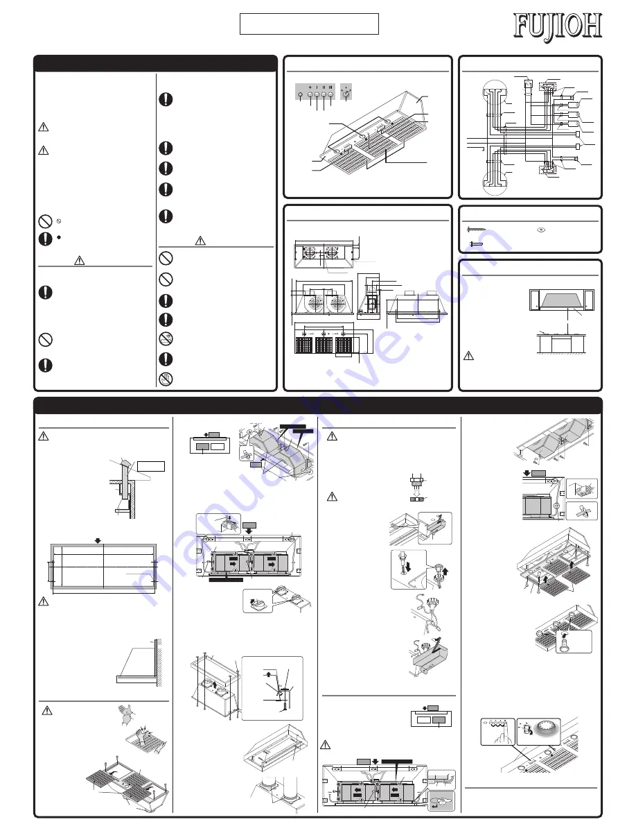
CIRCUIT DIAGRAM
6. Install this range hood to a liner. Check that the
hood is correctly installed, since incorrect
installation could result in the range hood
becoming detached and falling off.
DIMENSIONS
CAUTION:
WARNING:
WARNING:
Unit: inch (mm)
1
Place the range hood
as shown and detach
the left and right filters
by loosening 2 screws.
Then remove 4 screws
fixing the front cover
and detach the front
cover.
Note:
Pay attention
not to deform
the exhaust
ports.
Unit: inch (mm)
NAMES OF PARTS
RANGE HOOD LOCATION
1
The range hood must be installed just above the cooktop.
2
The minimum distance
from the cooking surface
to the bottom of the range
hood must be 24".
3
The total weight of the
BUF-08W range hood unit
is 68.2 lbs. (31 kg)
4
Power requirements are:
AC120 V, 60 Hz, 5.8 Amp
• Check that the hood is correctly installed, since incorrect installation
could result in the detachment of the range hood and the unit
could fall.
• To protect hands from injury, wear working gloves when installing
the range hood.
CAUTION:
ACCESSORIES
∅
6-15/16"(
∅
176)
44"(1117)
4-
∅
1/4"(4-
∅
6)
8-1/4"
(210)
2-3/8"
(61.3)
43" (1091.6)
10-13/16" (275) 6-1/8" (155)
31-11/16" (806.4)
14-13/16"
(376.8)
1-1/16"
(26.3)
2-3/16 "
(55.6)
17-1/2"(453.6)
5/8"(15)
14"(355.6)
3-1/8"(80)
2-7/16"(62)
7-7/8"(200)
45" (1143)
30" (762)
12-5/16"(314)
17-1/2"(453.6)
31-1/2"(800)
33-7/8"(860)
5-11/16"(145)
9/16"(14)
16-3/4"(425.5)
10-7/16"(265.4)
∅
7/8"(
∅
22.6)
11-3/4"(298)
24" (Minimum)
Cook top
Liner
FWD switches & lamps side
44" (1117)
16-7/8" (428.9)
43-3/16" (1096.3)
8-1/4" (210)
4-
∅
1/4" (4-
∅
6.5)
Non-flammable tape
Conduit
(Not supplied)
Nut
(Not supplied)
Wire cover
Hook
Lamp Switch
Fan Switch
Push to
turn ON
Turn the switch
clockwise
120V
60Hz
Connector
Connector
Connector
Connector
Connector
Connector
Connector
Connector
Motor
Motor
Red
Red
Or
ange
Or
ange
White
White
White
White
White
White
White
Blac
k
Blue
Blue
Bro
wn
Red
Or
ange
White
Blue
Bro
wn
Red
Or
ange
White
Blac
k
Blue
Bro
wn
Red
Or
ange
White
Blue
Bro
wn
Bro
wn
Or
ange
Blue
Bro
wn
Black
White
Black
Black
Blac
k
Black
Black
Black
Black
Black
White
Black
Black
White
Green
Black
Black
Grey
Grey
Grey
Grey
Black
Black
Yellow
Yellow
Yellow
Black
Black
Pilot Lamp
Pilot Lamp
Lamp:50W
Lamp:50W
Lamp:50W
Fan Switch
Fan Switch
Capacitor
Lamp Switch
Purple
Purple
Purple
Wood panel
Liner
Fan unit
Wall
3
Make sure that a wood panel for mounting
the range hood is fixed on the wall where
the range hood is installed.
Note:
If no wood panel is found on the
wall, be sure to prepare one
referring to the figure.
6
Make the duct joints secure and
air-tight using non-flammable
tape such as duct tape, etc.
(Not supplied)
Roof cap
Duct
(For vertical discharge)
Range hood
Soffit
Note:
2
×
7" or 1
×
10"~12"
round duct
3
Turn over the range hood
and detach the tape on
the exhaust ports.
3. TO REDUCE THE RISK OF FIRE, ELECTRIC
SHOCK, OR INJURY TO PERSONS, OBSERVE
THE FOLLOWING:
a) Installation work and electrical wiring must be
done by a qualified person(s) in accordance with
all applicable codes and standards, including fire-
rated construction.
• Black to Black
• White to White
• Green to Green
WARNING:
1U03 2681
7. Keep your hands and other objects away from
the fan while it is in motion. The range hood may
injure you or damage itself.
Screw M5
×
30
Four (4) pieces
Nut with plate
Four (4) pieces
Screw M4.5
×
45
Four (4) pieces
Detach the tape.
Tape
Front cover
Exhaust
port
Filter
Loosen 2 screws
to remove the filter.
Clamper
Keyhole
Keyhole
Clamper
Fan unit
FWD
Remove first
Remove second
Connector
Slide
Slide
Hook
Screw
Screw
Connector
Push with a
screwdriver etc,
and pull off.
Remove this side unit
FWD
Tighten screws
to fix
Liner
Liner
Nut with plate
[Right & left, each two (2) places]
Nut with plate
[Securing plate
turns while
passing through
the opening
of Liner]
Securing plate
Four screws
(M5
×
30)
5
Fix the range hood securely
using 4 supplied wood screws
(M4.5
×
45) to the holes on the
back of the range hood.
(2) Fix each fan unit using the
removed screws.
(5) Attach the front cover, and
secure it with 4 screws.
Then attach the filters.
Front cover
Screw
Filter
Slide
Slide
Hook
Screw
Attach this side unit
Keyhole
Bracket
Fan unit
Wire
FWD
Prior to function check, install
light bulbs (PAR20 bulb, with
base diameter 26 mm: medium
base), rated at 120 V - 50 Watt
or below.
The following light bulbs are
recommended for this range
hood.
(3) Connect each fan
unit’s wiring connector.
Note:
Be sure to connect
firmly as illustrated.
(4) Fasten each fan unit’s
wiring clamper.
Connector
Clamper
Clamper
Connector
FWD
Note:
Do not remove the keyhole screws.
(3) Remove screws attaching to the top plate.
(4) Disconnect wiring connector coming from the fan unit.
(5) Slide the fan unit rightward to disengage from fixing hook,
then pull it up while avoiding keyhole’s screws to remove from
the range hood.
2
Remove the fan units.
<Attention>
Note:
During installation, be careful not to
touch the fan switches. If two or more
switches are pushed at once, it may
be a cause of failure.
• GE Model No. 50PAR20H/FL25
• SYLVANIA Model No. 50PAR20/HAL/DL/NFL
Turn the lamps clock-wise to install.
Fan unit
Fan unit
Attach this unit first
FWD
Check that the fan unit is hanged securely on
the keyhole screw and fixing hooks when
attaching. It may be a cause of injury if dropped.
CAUTION:
(1) Release each fan unit’s
wiring clamper.
(2) Remove total 4 screws
from each unit.
Fan unit
Fan unit
Remove this unit first
FWD
7. Connect only to an AC120 Volt power source or
the range hood could result in fire, electric shock,
and damage.


