background image

i

DESKPOWER 2000 Series User’s Manual

Fujitsu endeavours to ensure that the information in this document is correct,

but accepts no liability for any error or omission in the same. Any procedures

described in this document for operating Fujitsu products should be read and

understood by the operator before such products are used. To ensure that Fujitsu

products function without risk to safety and health, such procedures should

be strictly obser ved by the operator. The development of Fujitsu products and

ser vices is continuous and published information may not be up to date.

Any particular issue of a product may contain facilities not described herein.

It is impor tant to check the current position with Fujitsu. Specifications and

statements as to per formance in this document are Fujitsu estimates intended for

general guidance. They may require adjustment in particular circumstances and

should therefore not be taken as formal of fers or commitments.

DESKPOWER is a trademark of Fujitsu Limited. The following are registered

trademarks of Microsoft Corporation: MS, MS-DOS, Windows

®

 NT, Windows

®

 for

Workgroups, Windows

®

 98. Pentium

®

 and MMX™ technology are trademarks of

Intel Corporation. Award is the registered trademark of Award Software

International Inc.

All other products are trademarks or registered trademarks of their respective

companies.

© Copyright 1999 Fujitsu Limited. All rights reser ved. No part of this publication

may be copied, reproduced, or translated without the prior written consent of

Fujitsu Limited. No part of this publication may be stored or transmitted in any

electronic form without the written consent of Fujitsu Limited.

© Copyright Fujitsu PC (Asia) Pte Ltd

Fujitsu PC (Asia) Pte Ltd
200 Pandan Loop
#05-03 Pantech 21
The Computer Centre
Singapore 128388
Tel:  65-776 0688
Fax: 65-776 0788

She int _i-xv

19/1/00, 16:27

1

Summary of Contents for DESKPOWER 2000 Series

Page 1: ...s intended for general guidance They may require adjustment in particular circumstances and should therefore not be taken as formal offers or commitments DESKPOWER is a trademark of Fujitsu Limited The following are registered trademarks of Microsoft Corporation MS MS DOS Windows NT Windows for Workgroups Windows 98 Pentium and MMX technology are trademarks of Intel Corporation Award is the regist...

Page 2: ... The openings should never be blocked by placing the product on a bed sofa rug or other similar surface This product should never be placed near or over a radiator or heat register or in a built in installation unless proper ventilation is provided 7 This product should be operated from the type of power indicated on the marking label If you are not sure of the type of power available consult your...

Page 3: ...ater d If the product does not operate normally when the operating instructions are followed Adjust only those controls that are covered by the operating instructions since improper adjustment of other controls may result in damage and will often require extensive work by a qualified technician to restore the product to normal condition e If the product has been dropped or the cabinet has been dam...

Page 4: ...iv Starting your PC for the first time ...

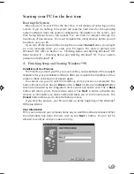
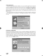
Page 5: ...p and Starting Windows 98 Conditions of Use Process The first time you start your PC you must confirm your acceptance of the copyright limitations for your pre installed software After you complete the Conditions of Use process these screens will not appear again You cannot use your PC until the Conditions of Use process is completed The bottom of each screen has a Back button a Next button and a ...

Page 6: ...on If you reject the terms of the license agreement you will be asked to review the license agreement for information on returning the Windows 98 or to shutdown your PC Certificate of Authenticity Look in the box that your PC came in and you will find a Windows 98 Certificate of Authenticity and a Windows 98 Users Manual On the certificate and also on the back of the manual you will find a barcode...

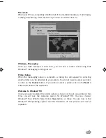
Page 7: ...box will appear for selecting which printer is to be attached to your system You do not have to select a printer so click on the Cancel button If you wish to select a printer click on the Next button and answer the questions Welcome to Windows 98 Once you have completed the printer setup or chosen not to set up a printer at this time you will see the welcome screen for Windows 98 You can choose Wi...

Page 8: ... and most application software have tutorials built in We highly recommend that you step through your tutorial before you use an application even if you are familiar with the same application on a different machine an earlier version of the application or a similar product Manuals In the accessories box you will find user manuals for Windows 98 or other pre installed software We recommend that you...

Page 9: ...ix About this manual ...

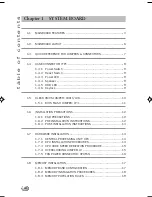
Page 10: ...hapters Chapter 1 System Board This chapter describes the system board and all its major components It contains the system board layout jumper settings cache and memory configuration and information on other internal devices Chapter 2 BIOS Configuration This chapter gives information about the system BIOS and tells how to configure the system by changing the settings of the BIOS parameters ...

Page 11: ...user Screen messages Denotes actual messages that appear on the screen a e s etc Represents the actual keys that you have to press on the keyboard NOTE Gives bits and pieces of additional information related to the current topic WARNING Alerts you to any damage that might result from doing or not doing specific actions ...

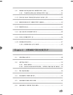
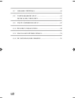
Page 12: ...0 1 5 1 BIOS FLASH JUMPER JP3 11 1 6 INSTALLATION PRECAUTIONS 12 1 6 1 ESD PRECAUTIONS 12 1 6 2 PRE INSTALLATION INSTRUCTIONS 12 1 6 3 POST INSTALLATION INSTRUCTIONS 13 1 7 HARDWARE INSTALLATION 14 1 7 1 CENTRAL PROCESSING UNIT CPU 14 1 7 2 CPU INSTALLATION PROCEDURES 14 1 7 3 CPU CORE SPEED DERIVATION PROCEDURE 15 1 7 4 OVERCLOCKING JUMPER J2 15 1 7 5 FAN POWER CONNECTOR CPUFAN 16 1 8 MEMORY INST...

Page 13: ...ODEM IN J6 24 1 13 AUX LINE IN CONNECTOR J5 25 1 14 CD IN CONNECTOR J8 26 1 15 EXPANSION CARDS 27 1 15 1 INSTALLING A PCI CARD 27 Chapter 2 AWARD BIOS SETUP 2 1 ENTERING SETUP 29 2 2 GETTING HELP 30 2 2 1 MAIN MENU 30 2 2 2 STATUS PAGE SETUP MENU OPTION PAGE SETUP MENU 30 2 3 THE MAIN MENU 30 2 4 STANDARD CMOS SETUP 32 2 5 ADVANCED BIOS FEATURES 34 2 6 ADVANCED CHIPSET FEATURES 37 ...

Page 14: ...ERIPHERALS 40 2 8 POWER MANAGEMENT SETUP 44 RELOAD GLOBAL TIMER EVENTS 47 2 9 PNP PCI CONFIGURATION SETUP 47 2 10 FREQUENCY VOLTAGE CONTROL 49 2 11 LOAD FAIL SAFE OPTIMIZED DEFAULTS 50 2 12 SET SUPERVISOR USER PASSWORD 51 ...

Page 15: ......

Page 16: ...e Intel 810 chipset to provide an efficient communication channel between the memory controller hub and I O hub controller The Intel 810 chipset contains three core components the Graphics and Memory Controller Hub GMCH GMCH0 the I O Controller Hub ICH0 ICH and the Firmware Hub FWH The GMCH integrates a 66 100MHz P6family system bus controller integrates 2D 3D graphics accelerator 100MHz SDRAM con...

Page 17: ...2 full IDE channels up to ATA66 only for ICH Low pin count interface for SIO Front Side Bus FSB 66 100MHz clocks are supported Main Memory Support two 168 pin DIMM sockets Support a maximum memory size of 256MB 64Mbit technology or 512MB 128Mbit technology SDRAM Slots Three 32 bit Master PCI Bus slots Support 3 3v 5v PCI bus Interface On Board IDE An IDE controller on the ICH ICH0 chipset provides...

Page 18: ...ex 8810 Hardware Audio Optional DirectSound hardware acceleration Post processing hardware Aureal Soft Wavetable Aureal Soft A3D Full Sound Blaster compatibility Aureal Enhanced Motorola Softmodem with Silicon DAA support BIOS The mainboard BIOS provides Plug Play BIOS which detects the peripheral devices and expansion cards of the board automatically The mainboard provides a Desktop Management In...

Page 19: ...Detect CPU Fan Control the fan will automatically stop when the system enters suspend mode System Voltage Detect CPU Overheat Warning Display Actual Current Voltage Other Features Keyboard Password Wake Up reserved Internal External Modem Wake Up ...

Page 20: ...et 370 DIMM 2 Top mouse Bottom keyboard Top Port 1 USB DIMM 1 IDE2 Bottom Port 2 IDE1 FDD ICH JMDM1 JFP1 JGS1 JBAT1 JWOL1 CD_IN AUX_IN COM B Top LPT Bottom COM A VGAPort Top Midi GamePort Bottom Line Out Line In Mic MODEM_IN CPUFAN SDRAM JKBV1 SDRAM AMR PTI FWH JGL1 J15 JP3 JP4 J9 J2 Aureal Vortex 8810 optional BATT CODEC J26 ...

Page 21: ...se Enabled onboard audio 2 3 Close Disabled onboard audio I O Ports Connector USB USB port IDE1 For Primary IDE port IDE2 For Secondary IDE port PS 2 For PS 2 Keyboard Mouse port FDD For Floppy port COMA For Serial port1 COM A COMB For Serial port2 COM B LPT For LPT port VGA For VGA port GAME For GAME port AUDIO For MIC LINE IN LINE OUT port JMDM1 For Internal Modem Ring Power ON port 1 3 QUICK RE...

Page 22: ... Keylock Power Switch Reset Switch Power LED Speaker and HDD LED are all connected to the JFP1 connector block JFP1 Power Switch Power LED Reset Switch HDD LED Speaker Buzzer short pin 14 15 Keylock LED Single Color Dual Color LED ...

Page 23: ...D ACPI request a 3 pin single color LED connect to pin 4 5 6 This LED will lit when the system is on b 2 pin dual color LED connect to pin 5 6 GREEN Color Indicate the system is in full on mode ORANGE Color Indicate the system is in suspend mode 1 4 4 Speaker Speaker from the system case is connected to this pin If on board Buzzer is available Short pin 14 15 On board Buzzer Enabled Open pin 14 15...

Page 24: ... pins of JBAT1 J26 to store the CMOS data Keep Data Clear Data 1 1 3 3 2 2 J26 1 3 JBA T1 1 3 Note You can clear CMOS by shorting 2 3 pin while the system is off Then return to 1 2 pin position Avoid clearing the CMOS while the system is on it will damage the mainboard Always unplug the power cord from the wall socket ...

Page 25: ...11 1 5 1 BIOS FLASH JUMPER JP3 This jumper is used to locked unlocked BIOS Flash This Jumper should be unlock when flashing programming the BIOS BIOS Flash Unlocked BIOS Flash Locked JP3 ...

Page 26: ... attach it to a metal part of the system unit before handling components If a wrist strap is not available maintain contact with the system unit throughout any procedure requiring ESD protection 1 6 2 PRE INSTALLATION INSTRUCTIONS Always observe the following before you install a system component 1 Turn off the system power and all the peripherals connected to the unit before opening it 2 Open the...

Page 27: ...ng a system component 1 See to it that the components are installed according to the step by step instructions in their respective sections 2 Make sure you have set all the required jumpers See Section 1 6 for the correct jumper settings 3 Replace any expansion boards or peripherals that you removed earlier 4 Replace the system cover 5 Connect the necessary cables and turn on the system ...

Page 28: ...n attached to prevent overheating 1 7 2 CPU INSTALLATION PROCEDURES 1 Pull the lever sideways away from the socket Then raise the lever up to a 90 degree angle 2 Locate Pin 1 in the socket and look for the white dot or cut edge in the CPU Match Pin 1 with the white dot cut edge Then insert the CPU It should insert easily 3 Press the lever down to complete the installation CPU CPU Open Lever Pin 1 ...

Page 29: ...can be set through BIOS setup Default setting enables auto detection of CPU speed 1 7 4 OVERCLOCKING JUMPER J2 Overclocking is operating a CPU Processor beyond its specified frequency J2 jumper is used for overclocking J2 J2 Short Function Automatically detect CPU Bus Frequency ...

Page 30: ...m Hardware Monitor chipset on board you must use a specially designed fan with speed sensor to take advantage of this function CPUFAN 12V S E N S O R GND For fans with fan speed sensor every rotation of the fan will send out 2 pulses System Hardware Monitor will count and report the fan rotation speed Note 1 Always consult vendor for proper CPU cooling fan 2 CPU FAN supports the FAN control You ca...

Page 31: ...inboard supports a maximum memory size of 256MB 64 bit technology or 512MB 128 bit technology for SDRAM It provides two 168 pin unbuffered DIMMs Double In Line Memory Module sockets It supports 8 MB to 128 Mbytes DIMM memory module DIMM1 Bank0 Bank1 DIMM2 Bank2 Bank3 ...

Page 32: ...DIMM 1 The DIMM slot has 2 Notch Keys VOLT and DRAM so the DIMM memory module can only fit in one direction 2 Insert the DIMM memory module vertically into the DIMM slot Then push it in VOLT DRAM 3 The plastic clip at the side of the DIMM slot will automatically close Single Sided DIMM ...

Page 33: ...ssing and the size supported by the mainboard is shown below Table 1 2 SDRAM Memory Addressing DRAM Tech 16M 64M 64M DRAM Density Width 1Mx16 2Mx8 2Mx32 2Mx32 4Mx16 4Mx16 8Mx8 2Mx32 4Mx16 8Mx8 DRAM Addressing ASYM ASYM ASYM ASYM ASYM ASYM ASYM ASYM ASYM ASYM Row Column 11 8 11 9 11 9 12 8 11 10 13 8 13 9 11 8 12 8 12 9 Single Side S Double Side D MB DIMM Address Size 8MBx4 16MBx8 16MBx8 32MBx16 32...

Page 34: ...20 1 9 POWER SAVING SWITCH CONNECTOR JGS1 Attach a power saving switch to JGS1 When the switch is pressed the system immediately goes into suspend mode Press any key and the system wakes up JGS1 ...

Page 35: ...ected to JGL1 the light will turn green when system is On During sleep mode the 2 pin LED will change color from Green to Orange For 3 pin LED when LED is connected to JGL1 this will light when the system is On and blinks when it is in suspend sleep mode 3 pin LED 2 pin LED 1 2 Single Color 1 2 Dual Color 1 3 Blink 1 3 Green Color Orange Color 1 3 Green Color Orange Color JGL1 1 3 ...

Page 36: ...22 1 10 ONBOARD AUDIO ENABLED DISABLED JUMPER JP4 This jumper is used to Enabled Disabled the onboard audio Enabled Disabled 1 1 3 3 JP4 1 3 ...

Page 37: ... on card that supports the Modem Wake Up function JMDM1 1 5 Note Modem wake up signal is active low Note To be able to use this function you need a power supply that provide enough power for this feature Power supply with 750ma 5V Stand by PIN SIGNAL 1 NC 2 GND 3 MDM_WAKEUP 4 NC 5 5VSB ...

Page 38: ... MODEM IN J6 The connector is for Modem with internal voice connector SPK_IN is connected to the Modem Speaker Out connector MIC_OUT is connected to the Modem Microphone In connector Modem_In SPK IN GND MICOUT ...

Page 39: ...25 1 13 AUX LINE IN CONNECTOR J5 This connector is used for DVD Add on Card with Line In connector AUX_IN LGNDR ...

Page 40: ...26 1 14 CD IN CONNECTOR J8 This connector is for CD ROM audio connector CD_In LGNDR ...

Page 41: ...n the slot board 2 Remove the bracket on the housing opposite to the empty PCI slot 3 Insert a PCI card into the slot Make sure that the card is properly seated 4 Secure the card to the housing with a screw When you turn on the system BIOS automatically detects and assigns resources to the PCI devices ...

Page 42: ...28 ...
Page 43: ...riefly at the bottom of the screen during the POST Power On Self Test press Del key or simultaneously press Ctrl Alt and Esc keys TO ENTER SETUP BEFORE BOOT PRESS CTRL ALT ESC OR DEL KEY If the message disappears before you respond and you still wish to enter Setup restart the system to try again by turning it OFF then ON or pressing the RESET button on the system case You may also restart by simu...

Page 44: ...etup functions and two exit choices Use arrow keys to select among the items and press Enter to accept or enter the sub menu CMOS Setup Utility Copyright C 1984 1999 Esc Quit Select Item F10 Save Exit Setup Shift F2 Change Color Load Fail Safe Defaults Load Optimized Defaults Set Supervisor Password Set User Password Save Exit Setup Exit Without Saving STANDARD CMOS Feature Advanced BIOS Feature A...

Page 45: ...CI Frequency Voltage Control Use this menu to specify your settings for frequency voltage control Load Fail Safe Defaults Use this menu to load the BIOS default values for the minimal stable performance for your system to operate Load Optimized Defaults Use this menu to load the BIOS default values that are factory settings for optimal performance system operations Supervisor User Password Use thi...

Page 46: ...31 can be keyed by numeric function keys year The year depends on the year of the BIOS Time The time format is hour minute second CMOS Setup Utility Copyright C 1984 1999 Award Software Standard CMOS Setup Date mm dd yy Fri Feb 28 1999 Time hh mm ss 00 00 00 IDE Primary Master Press Enter 2557MB IDE Primary Slave Press Enter None IDE Secondary Master Press Enter None IDE Secondary Slave Press Ente...

Page 47: ...ur own drive type manually If you select Manual related information is asked to be entered to the following items Enter the information directly from the keyboard This information should be provided in the documentation from your hard disk vendor or the system manufacturer If the controller of HDD interface is SCSI the selection shall be None If the controller of HDD interface is CD ROM the select...

Page 48: ...igure 2 3 Advance BIOS Features Setup Anti Virus Protection Allows you to choose the VIRUS Warning feature for IDE Hard Disk boot sector protection If this function is enabled and someone attempt to write data into this area BIOS will show a warning message on screen and alarm beep CPU Internal Cache The default value is Enabled Enabled default Enable cache Disabled Disable cache Note The internal...

Page 49: ...the operating system from the devices in the sequence selected in these items The settings are Floppy LS ZIP HDD 0 HDD 1 HDD 2 HDD 3 SCSI CDROM LAN and Disabled Swap Floppy Drive Switches the floppy disk drives between being designated as A and B Default is Disabled Boot Up Floppy Seek During POST BIOS will determine if the floppy disk drive installed is 40 or 80 tracks 360K type is 40 tracks whil...

Page 50: ...t the keystroke The settings are 250 500 750 1000 Security Option This category allows you to limit access to the system and Setup or just to Setup System The system will not boot and access to Setup will be denied if the correct password is not entered at the prompt Setup default The system will boot but access to Setup will be denied if the correct password is not entered at the prompt OS Select...

Page 51: ... the chipset CMOS Setup Utility Copyright C 1984 1999 Award Software Advanced Chipset Features Item Help Menu Level SDRAM CAS Latency Time Auto SDRAM Cycle Time Tras Trc 6 8 SDRAM RAS to CAS Delay 3 SDRAM RAS Precharge Time 3 System BIOS Cacheable Disabled Video BIOS Cacheable Disabled Memory Hole at 15M 16M Disabled Delayed Transaction Disabled On Chip Video Window Size 64MB Move Enter Select PU ...

Page 52: ...ay fail to retain data Fast gives faster performance and Slow gives more stable performance This field applies only when synchronous DRAM is installed in the system The settings are 2 and 3 System BIOS Cacheable Selecting Enabled allows caching of the system BIOS ROM at F0000h FFFFFh resulting in better system performance However if any program writes to this memory area a system error may result ...

Page 53: ... buffer to support delay transactions cycles Select Enabled to support compliance with PCI specification version 2 1 The settings are Enabled and Disabled On Chip Video Window Size Select the on chip video window size for VGA driver use The settings are 32MB 64MB Disabled ...

Page 54: ...ton Only KB Power On Password Hot Key Power On Onboard FDC Controller Enabled Onboard Serial Port 1 3F8 IRQ4 CMOS Setup Utility Copyright C 1984 1999 Award Software Integrated Peripherals Onboard Serial Port 2 2F8 IRQ3 UART Mode Select Normal RxD TxD Active Hi Lo IR Transmition Delay Enabled Onboard Parallel Port 378 IRQ7 Parallel Port Mode SPP EPP Mode Select EPP 1 7 ECP Mode use UDMA 3 PWRON Aft...

Page 55: ... driver Windows 95 OSR2 or a third party IDE bus master driver If your hard drive and your system software both support Ultra DMA 33 and Ultra DMA 66 select Auto to enable BIOS support The settings are Auto Disabled USB Controller Select Enabled if your system contains a Universal Serial Bus USB controller and you have USB peripherals The settings are Enabled Disabled USB Keyboard Support Select E...

Page 56: ...installed on the system board and you wish to use it If you install add on FDC or the system has no floppy drive select Disabled in this field The settings are Enabled and Disabled Onboard Serial Port 1 Port 2 Select an address and corresponding interrupt for the first and second serial ports The settings are 3F8 IRQ4 2E8 IRQ3 3E8 IRQ4 2F8 IRQ3 Disabled Auto UART Mode Select This item allows you t...

Page 57: ...onboard parallel port is EPP Spec compliant so after the user chooses the onboard parallel port with the EPP function the following message will be displayed on the screen EPP Mode Select At this time either EPP 1 7 spec or EPP 1 9 spec can be chosen SPP EPP ECP ECP EPP PWRON After PWR FAIL This option will determine how the system will power on after a power failure The setting are Former sts For...

Page 58: ...eo Off Method DPMS Video Off In Suspend Yes Suspend Type Stop Grant Modem Use IRQ 3 Suspend Mode Disabled HDD Power Down Disabled Soft Off by PWRBTN Instant Off Wake Up by PCI Card Disabled Power On by Ring Wake Up on LAN Disabled CPU Thermal Throtting 62 57 Resume By Alarm Reload Global Timer Events Primary IDE 0 Disabled Primary IDE 1 Disabled Secondary IDE 0 Disabled Secondary IDE 1 Disabled FD...

Page 59: ...re from 1 min to 1 hr except for HDD Power Down which ranges from 1 min to 15 min and disable Video Off Method This determines the manner in which the monitor is blanked V H SYNC Blank This selection will cause the system to turn off the vertical and horizontal synchronization ports and write blanks to the video buffer Blank Screen This option only writes blanks to the video buffer DPMS default In...

Page 60: ...bled and Disabled Power on by Ring Wake Up on LAN To use this function you need a LAN add on card which support power on functions It should also support the wake up on LAN jumper JWOL1 CPU Thermal Throttling Select the CPU THRM Throttling rate The settings are 25 0 37 5 50 0 62 5 75 0 87 5 Resume by Alarm This function is for setting date and time for your computer to boot up During Disabled you ...

Page 61: ...er Interconnect is a system which allows I O devices to operate at speeds nearing the speed the CPU itself uses when communicating with its own special components This section covers some very technical items and it is strongly recommended that only experienced users should make any changes to the default settings CMOS Setup Utility Copyright C 1984 1999 Award Software PnP PCI Configuration Setup ...

Page 62: ...oot and Plug and Play compatible devices However this capability means absolutely nothing unless you are using a Plug and Play operating system such as Windows 95 98 If you set this field to manual choose specific resources by going into each of the sub menu that follows this field a sub menu is preceded by a The settings are Auto ESCD Manual IRQ Resources When resources are controlled manually as...

Page 63: ...o Item Help Menu Level Auto Detect DIMM PCI CLK This item allows you to enable disable auto detect DIMM PCI Clock The settings are Enabled Disabled CPU Clock Spread Spectrum This item allows you to set the CPU Clock Spread Spectrum CPU Ratio This item allows you to select the CPU ratio Move Enter Select PU PD Value F10 Save ESC Exit F1 General Help F5 Previous Values F6 Fail safe defaults F7 Optim...

Page 64: ... Safe Defaults Y N N Pressing Y loads the BIOS default values for the most stable minimal performance system operations Load Optimized Defaults When you press Enter on this item you get a confirmation dialog box with a message similar to Load Optimized Defaults Y N N Pressing Y loads the default values that are factory settings for optimal performance system operations ...

Page 65: ...ion and not enter a password To disable a password just press Enter when you are prompted to enter the password A message will confirm the password will be disabled Once the password is disabled the system will boot and you can enter Setup freely PASSWORD DISABLED When a password has been enabled you will be prompted to enter it every time you try to enter Setup This prevents an unauthorized perso...

Page 66: ...ntech 21 The Computer Centre Singapore 128388 Tel 65 776 0688 Fax 65 776 0788 Fujitsu PC Asia Pte Ltd Malaysia Branch 8th Floor Wisma Damansara Jalan Semantan 50490 Kuala Lumpur Malaysia Tel 603 253 3997 Fax 603 253 4245 Website www fujitsu pc asia com ...

Reviews: