background image

PRIMERGY

PRIMERGY H200
Server System   


Jürgen Mührs/Xenia Fierley
Fujitsu Siemens Computers GmbH Primergy
81730 Munich
e-mail: email: manuals@fujitsu-siemens.com
Tel.: (0 89) 610 01-158/157
Fax: (++49) 700 / 372 00000
U41147-J-Z156-2-76
Sprachen:  En          

Edition September 2001

Summary of Contents for PRIMERGY H200

Page 1: ...ver System Jürgen Mührs Xenia Fierley Fujitsu Siemens Computers GmbH Primergy 81730 Munich e mail email manuals fujitsu siemens com Tel 089 61001 158 157 Fax 49 700 372 00000 U41147 J Z156 2 76 Sprachen En Edition September 2001 ...

Page 2: ...s your comments are included at the back of the manual There you will also find the addresses of the relevant User Documentation Department Copyright and Trademarks Copyright 2001 Fujitsu Siemens Computers GmbH All rights reserved Delivery subject to availability right of technical modifications reserved All hardware and software names used are trademarks of their respective manufacturers This man...

Page 3: ...portant notes Installation Preparation for use and operation Opening and closing the server Property and data protection Troubleshooting and tips System components and expansions SCSI configurations Appendix Continued ...

Page 4: ......

Page 5: ...Related publications and index ...

Page 6: ......

Page 7: ...nd model 25 3 3 1 Mounting the front doors 25 3 4 Installing the rack model 26 3 5 Connecting devices to the rack model 29 3 5 1 Routing the cables 31 3 6 Connecting the server to the line voltage 35 3 7 Instructions on connecting and disconnecting cables 36 4 Preparation for use and operation 37 4 1 Unlocking the floorstand model 37 4 2 The control panel 38 4 2 1 Operation controls 39 4 2 2 Indic...

Page 8: ...ect 56 7 9 System will not boot 56 7 10 Drives are reported as dead 57 7 11 Added drive reported defective 57 7 12 Error messages on the screen 58 7 13 Error messages on the control panel 58 8 System components and expansions 63 8 1 SCSI hard disk subsystem 64 8 1 1 Handling Hard Disk Drives Modules 65 8 1 2 SCSI hard disk drives 66 8 1 3 Swapping SCSI hard disk drives during operation 68 8 1 4 In...

Page 9: ... channel version 95 9 2 3 Internal SCSI configurations 2 channel version 96 10 Appendix 97 10 1 Removing mounting the front panel 98 10 2 Removing the cage for the hard disk drives 99 10 3 Converting 1 to 2 channel version 1 6 inch HD subsystem 101 10 4 Upgrading second SCSI backplane 1 inch HD subsystems 104 10 5 Upgrading external SCSI interface 109 10 6 Converting a floorstand model into a rack...

Page 10: ......

Page 11: ...oors of the floorstand model can be monitored centrally As a rack model the lockable front door of the rack offers additional security This operating manual tells you how to put your server into operation how to operate it in daily use and how to expand your server I Steps which are identical for the floorstand model and rack model are only described for the floorstand model Steps which are identi...

Page 12: ... required and allows the internal hard disk drive modules to be attached or detached without problems The hard disk subsystem is designed for Ultra3 SCSI LVD The hard disk subsystem can be controlled by the onboard standard controller or by a disk array controller If the server is equipped with a disk array controller hard disk drives can also be replaced during operation hot swapping For more inf...

Page 13: ...erver management Server management is implemented with the aid of the supplied ServerView software and PDA Prefailure Detection and Analyzing technology The PDA analyzes and monitors all components relevant to system reliability thus enabling early detection of overload situations and appropriate troubleshooting ServerView enables the management of all PRIMERGY servers in the network via a central...

Page 14: ...le maintenance The flash EPROM program supplied with the FSC utilities supports fast BIOS update With the optional Remote Test and Diagnostic System RemoteView long distance maintenance and service remote can also be performed on servers of the PRIMERGY series 1 2 Notational conventions The meanings of the symbols and fonts used in this manual are as follows V CAUTION Pay particular attention to t...

Page 15: ...ormation provided for users the editorial department responsible for this manual has been independently audited to verify its high standards of quality of the documentation This audit was carried out by TÜV PRODUCT SERVICE GmbH The following aspects were investigated General comprehensibility User friendliness Occupational hygiene and safety for the users Safety of the application and observance o...

Page 16: ...W Apparent power 700 VA Heat emission 2500 kJ h Building fuse 16 A Protection class I Product safety IEC 950 EN 60950 UL 1950 CSA 22 2 Nr 950 Electromagnetic compatibility FCC class A Interference emission EN 55022 Interference immunity EN 50082 1 CE certification to EU directives 73 23 EEC low voltage directive 89 336 EEC electromagnetic compatibility Dimensions Floorstand Model Rack Model Width ...

Page 17: ... floorstand model 1 2 m on the left side The maintenance area may also be used but must be quickly accessible Environmental conditions Condensation during operation must be avoided Noise level Environment class 3K2 Environment class 2K2 DIN IEC 721 part 3 3 DIN IEC 721 part 3 2 Temperature Operating 3K2 Transport 2K2 10 C 35 C 25 C 60 C Foreign particles Humidity Floating dust 20 80 0 15 mg m or l...

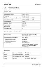
Page 18: ...8 U41147 J Z156 2 76 Technical data Introduction ...

Page 19: ...U41147 J Z156 2 76 9 Introduction Technical data ...

Page 20: ......

Page 21: ...U41147 J Z156 2 76 11 Introduction Technical data ...

Page 22: ...12 U41147 J Z156 2 76 Technical data Introduction ...

Page 23: ...ctronic office machines for use in an office environment If you have any questions contact your sales office or our customer service Before operating the device V CAUTION During installation and before operating the device observe any instructions on environmental conditions see section Technical data on page 6 If the device is brought in from a cold environment condensation may form both inside a...

Page 24: ...lug from the grounded power outlet Connect the device and the attached peripherals to the same circuit data loss Route the cables in such a way that they do not form a potential hazard make sure nobody can trip over them and that they cannot be damaged When connecting a device refer to the relevant notes in this manual Never connect or disconnect data transmission lines during a storm lightning ha...

Page 25: ... electromagnetic compatibility relating to telecommunications terminal equipment If you install other expan sions you may damage the system or violate the safety regulations and regulations governing RFI suppression Information on which system expansions are suitable can be obtained from customer service or your sales office The components e g power supply marked with a warning sign e g lightning ...

Page 26: ...ard or chapter Related publications on page 131 Do not throw batteries in the trash The battery must be disposed of in accordance with local regulations concerning special waste Replace the lithium battery on the system board in accordance with the instructions in the technical manual for the system board Data cables to peripheral devices must be adequately shielded Note on the laser The CD ROM dr...

Page 27: ...touching a grounded object before working The equipment and tools you use must be free of static charge Pull out the power plug before inserting or pulling out boards Always hold boards by their edges Never touch pins or conductors on boards Other important points When cleaning the server observe the relevant notes in the section Cleaning the server on page 46 Keep this operating manual and all ad...

Page 28: ...However there is no guarantee that interference will not occur in a particular installation If this equipment does cause harmful interference to radio or television reception which can be determined by turning the equipment off and on the user is encouraged to try to correct the interference by one or more of the following measures Reorient or relocate the receiving antenna Increase the separation...

Page 29: ...ntation for your PRIMERGY system and the comments in the Important notes chapter in the 19 inch rack operating manual supplied with the rack Ensure that the anti tilt bracket is correctly mounted when you set up the rack For safety reasons no more than one unit may be withdrawn from the rack at any one time during installation and maintenance work If more than one unit is withdrawn from the rack a...

Page 30: ...ve to be switched on permanently should not be switched on until they are used and should be switched off during long breaks and upon completion of work Notes on packaging We recommend that you do not throw away the original packaging in case you need it later for transporting your system unit If possible the system unit and the devices should only be transported in their original packaging Notes ...

Page 31: ...emens Computers GmbH Recycling Center D 33106 Paderborn Phone 49 5251 818010 Fax 49 5251 818015 Further information on environmental protection The Fujitsu Siemens Computers GmbH representative for environmental protection will be pleased to answer any further questions you may have concerning environmental protection Fujitsu Siemens Computers GmbH Environmental Protection Werner von Siemens Straß...

Page 32: ......

Page 33: ... areas of the monitor or the server 3 1 Installation steps Ê Unpack the server see next section Unpacking the server Ê Put the floorstand model in position or mount the rack model in the rack see layout diagram on the order lists created with the Rack Architect program Ê Attach the cables according to the configuration required see also section Instructions on connecting and disconnecting cables o...

Page 34: ...rt at some later date Ê Unpack all the individual parts Ê Check the delivery for damage incurred during transport Ê Check whether the delivery agrees with the details in the delivery note The model rating plate is located on the left hand side of the server Should you discover that the delivery does not correspond to the delivery note notify your supplier immediately The floorstand model is fitted...

Page 35: ...ce are observed The rear of the server must be accessible in order to connect it to external devices The power plug must be easily and safely accessible To ensure sufficient ventilation of the system a minimum clearance of 200 mm must be provided at the front and the rear of the server 3 3 1 Mounting the front doors The doors are delivered separately Ê Unpack the front doors Figure 2 Mounting the ...

Page 36: ...e of the server Cage nuts and spring nuts also must be inserted in the support uprights The support bracket is used to fix the rear of the left carrier rail the cage nuts are used to fix the support bracket and the front panel and the spring nuts are used to fix the carrier rails Ê As an aid refer to the fitting instructions in the technical manual for the corre sponding rack Ê Using the mounting ...

Page 37: ... key provided Please note that the guide nubs of the rails next to the spring nuts must fit into the holes in the support uprights and in the support bracket and that the telescope bar must afterwards be able to extend fully to the front Figure 4 Pulling the telescope bars out toward the front Ê Pull the mounted telescope bars completely out toward the front They must click into place so that you ...

Page 38: ...oses 1 protrude over and grip the bars Ê Adjust the server so that the bore holes of the telescope bars and of the server line up Keep the telescope bars engaged Ê Screw the telescope bars to the server on the left and right six screws altogether The following steps require only one person Figure 6 Telescope bar with safety spring Ê Press in the safety springs 1 on both telescope bars 1 1 ...

Page 39: ... are on the rear of the server Which ports are available on your server depend on the boards installed The standard ports are indicated by symbols see figure 8 on page 30 and by color coding for the connectors 1 Mouse port green 2 CAN bus port 3 Serial port COM2 turquoise 4 USB 1 Universal Serial Bus port black 5 Parallel port LPT printer port burgundy 6 LAN port 7 Monitor port blue 8 USB 2 Univer...

Page 40: ...30 U41147 J Z156 2 76 Connecting devices to the rack model Installation Figure 8 PRIMERGY H200 ports floorstand model rack model 1 2 8 7 6 9 3 4 5 1 0 1 1 2 1 2 1 8 7 6 9 5 1 0 2 1 2 1 1 1 3 1 2 4 ...

Page 41: ...be used Instead connect the data cable of the monitor to the monitor port of the graphics card Ê Connect the data cables at the server and peripherals 3 5 1 Routing the cables 19 inch rack 23 HU and 42 HU If the server is installed in a 19 inch rack without cord management an artic ulated cable guide must be mounted on the device Ê Insert two spring nuts in the groove of the right rear support upr...

Page 42: ...ulated cable guide has a supplementary joint which that facili tates the folding away In order to release the supplementary joint the spring 5 must be pressed upwards The spring of the joint locks automatically by folding back the articulated cable guide Limited cable laying When operating in the single ended SCSI mode the maximum cable length for external SCSI cables 1 50 m and 1 80 m respectivel...

Page 43: ... back into the cable clips Unlimited cable laying For SCSI LVD operation the SCSI cables can be fastened to the articulated cable guides The internal hard disk modules can thus be pulled out later without any further preparations Ê Route the cables via the articulated cable guide and secure them with cable ties Ê Check to see if the internal hard disk modules can be pulled out without breaking or ...

Page 44: ...ing the cables in the DataCenter rack Ê Route the cables through the cable clips on the right support upright after having inserted the server see the technical manual of the DataCenter rack Ê Check to see if the server can be pulled out without breaking or overstretching the cables 1 2 ...

Page 45: ...ion The power supply units automatically adjust to a voltage range from 100 V to 240 V Figure 11 Connecting the floorstand model to the line voltage Ê Plug the delivered power cord into the insulated socket of the server 1 and into a properly grounded power outlet of the main AC supply circuit 2 With the rack model you can also plug the power cord into the grounded socket strip on the rack 2 see t...

Page 46: ... disconnect the cables in the order described below Connecting cables Ê Turn off all power and equipment switches Ê Pull all power plugs out of the grounded power outlets Ê Plug all cables into the server and peripherals Ê Plug all data communication cables into the utility sockets Ê Plug all power cables into the grounded power outlets Disconnecting cables Ê Turn off all power and equipment switc...

Page 47: ... model and rack model are only described for the floorstand model For more detailed information about the rack refer to the technical manual for the rack 4 1 Unlocking the floorstand model The front doors are continuously monitored by the system Figure 12 Unlock the server Ê Turn the key 90 clockwise 1 Ê Open the left front door 2 Ê Turn the key a further 90 to open the right front door 3 2 1 3 2 ...

Page 48: ...control panel Figure 13 The control panel 1 Floppy disk drive 2 Floppy disk drive indicator 3 Power on indicator 4 Hard disk drive indicator 5 Key switch 6 Power switch 7 LCD panel 8 Reset button 9 Menu button 10 CPU error indicator 11 System error indicator 1 2 3 4 5 6 7 9 1 0 1 1 8 ...

Page 49: ... operative When the system is switched off pressing the power switch boots the system When the system is operating pressing the power switch switches off the system Pressing the reset button reboots the system The reset button has only one effect when the system has already been booted The menu button is operative Power Switch When the system is switched off it is switched on by pressing the power...

Page 50: ...ch position For additional infor mation refer to the section LCD panel on page 41 Power on indicator Lights orange when the server is switched off but mains voltage is present standby mode Lights green when the server is switched on Hard disk drive indicator Lights green when the SCSI drives in the internal hard disk modules are being accessed System error indicator Lights orange when serious syst...

Page 51: ...ne second The menu button is inoperative during the start up phase If no system errors occur during the start up phase the LCD panel switches to the system infor mation mode The system information mode is the normal display mode If errors occur during operation the LCD panel automatically switches to the system error mode and remains in this mode until the display mode is changed with the menu but...

Page 52: ... can find on the ServerStart CD under the menu item Tools is used to enter the infor mation The system information is not lost when the system is rebooted Examples of possible system information messages A few examples of system information messages which can be entered with the SCU tool are given below Server name node System ok IP address Cluster address Operating system and version No of CPUs a...

Page 53: ...e section Flickering stripes on monitor screen on page 55 The power switch does not disconnect the server from the line voltage To disconnect the line voltage completely remove the power plug from the grounded power outlet Ê Set the key switch in the control panel to the Local position Server is switched off Ê Press the power switch The server switches on performs a system test and starts the oper...

Page 54: ...s information about the server configuration and how to install the operating system 4 4 1 Configuration with ServerStart With the ServerStart CD provided you can configure the server and install the operating system in a convenient manner The menu guided configuration includes server configuration with SCU and the disk array controller configu ration with GAM Global Array Manager and the Adaptec ...

Page 55: ...the onboard SCSI controller Configure the onboard SCSI controller as described in the technical manual for the system board and or in the readme files on the corresponding driver diskettes 4 4 3 Installing the operating system Ê Insert the installation disk and the CD of the operating system you want to install Ê Reboot the server Ê Follow the instructions on the screen and in the manual for the o...

Page 56: ... to a service technician Do not use any cleaning agents that may contain abrasives or corrode plastic Ensure that no liquid enters the system Ensure that the ventilation areas of the server and the monitor are free Use a cloth to disinfection and clean the keyboard and the mouse Wipe the server and monitor casing with a dry cloth If particularly dirty use a cloth which has been moistened in mild d...

Page 57: ...n on page 23 and System components and expansions on page 63 5 1 Removing mounting the front doors Ê Unlock the server see section Unlocking the floorstand model on page 37 Ê Remove the key Figure 14 Removing the front doors Ê Remove the open front doors by lifting them up 1 and out 2 Mounting is done in the reverse order see also section Mounting the front doors on page 25 1 2 ...

Page 58: ...rver 5 2 Removing mounting top cover The top cover of the housing prevents you from taking off the side covers Figure 15 Removing the top cover Ê Remove the knurled screw 1 push the top cover back 2 and remove it by lifting upward 3 Mounting is done in the reverse order 1 3 1 2 ...

Page 59: ...roller SCSI controller network controller etc to make changes to the processor or base memory configuration or to replace fans then remove the left side cover Figure 16 Removing the side cover Ê Remove the side cover by lifting it upward 1 Mounting is done in the reverse order I Make sure that the side fits into the gap between the base of the housing and the housing itself 1 1 ...

Page 60: ...um V CAUTION Before you remove the slot cover the server must be switched off and the power plug pulled out otherwise the safety switch will switch off the server when the slot cover is removed Figure 17 Removing the slot cover Ê Loosen the knurled screw 1 Ê Use the recessed grips a to push the slot cover to the rear 2 Ê Lift the slot cover off the housing in the direction 3 indicated by the arrow...

Page 61: ...ized access you can use the BIOS Setup security functions 6 1 BIOS Setup security functions The Security menu in BIOS Setup offers various options for protecting your data from unauthorized access By combining these options you can achieve optimum protection for your system I You will find a detailed description of the Security menus and how to assign passwords in the manual for the BIOS Setup Pre...

Page 62: ... the Security menu Prevent unauthorized writing of diskettes To activate this protection select the value Disabled for the Diskette Write field in the Security menu Protect BIOS from being overwritten To activate this protection select the value Disabled for the Flash Write field in the Security menu Protect the server from being switched on by an external device To activate this protection select...

Page 63: ...oblem proceed as follows Ê Make a list of the steps and the circumstances that led to the fault Also make a list of any error messages displayed Ê Switch the server off Ê Contact customer service 7 1 Power on indicator remains dark The power on indicator remains dark after you switch on your device Power cord incorrectly connected Ê Make sure that the power cable is correctly connected to the serv...

Page 64: ... enter the appropriate password when necessary Brightness control is set to dark Ê Set the brightness control to light For detailed information please refer to the operating manual supplied with your monitor Power cable or monitor cable not connected Ê Switch off the monitor and the server Ê Check whether the power cable is properly connected to the monitor and to the power outlet Ê Check whether ...

Page 65: ...er software for the screen controller for how to set the correct horizontal frequency for your monitor and follow the procedure accordingly 7 5 No screen display or display drifts The wrong horizontal frequency or resolution has been selected for the monitor or for the application program Ê Find out which horizontal frequency your monitor screen supports You will find the horizontal frequency also...

Page 66: ...ck whether the write protection of the floppy disk is activated Ê In the BIOS Setup check the entry for the floppy disk drive Ê In the BIOS Setup check whether the diskette drive controller and write permissions are enabled see the technical manual for the system board Ê Check that the cables of the floppy disk drive are properly connected refer to the section Installing removing the floppy disk d...

Page 67: ...oller configuration is incorrect Ê Check and correct the settings for the drives with the RAID configuration program Further information is provided in the manual for the disk array controller 7 11 Added drive reported defective This error message may occur when the server has a disk array controller Disk array controller is not configured for this hard disk drive The drive was probably installed ...

Page 68: ...rror messages Message Cause Reaction RED_FAN _FAILED Fan no in the redundant cooling system has failed Exchange the fan redundant fan undertakes cooling FAN _FAILED Fan no in the non redundant cooling system has failed Exchange the fan V CAUTION Cooling is no longer ensured system may overheat FAN _CRITICAL Fan no does not run with full power rotation speed Exchange the fan in a reasonable amount ...

Page 69: ...n redundant power supply unit no has failed Exchange the power supply unit PS_OVERLOAD Power supply unit overloading Contact our service organi zation and or install a supplementary power supply unit INTRUSION_DETECT Front door was opened Close the front door _TOO_LOW Voltage to low Contact our service organi zation _TOO_HIGH Voltage to high Contact our service organi zation SERR_ON_PCIBUS SERR sy...

Page 70: ...tem and or no CPU detected not correctly mounted or CPU termi nator module not installed Check CPU s and or CPU terminator module s for correct mounting AC_FAIL Power failure occurred Check the fuses and the power cable POWER_OK All voltages reached the proper values No error this message only provides extra information NO_TRANSLATION Unknown error code occurred no translation is available Contact...

Page 71: ...U41147 J Z156 2 76 61 Troubleshooting and tips Error messages on the control panel ...

Page 72: ......

Page 73: ...s on page 131 I You will find an overview and a brief description of the installed system boards on the left hand side cover of the server A detailed description of the system board is provided in the corresponding technical manual V CAUTION Please take note of the safety information in the chapter Important notes on page 13 V CAUTION If you do not wish to carry out hot plug operations then shut d...

Page 74: ...modules are equipped with a hard disk drive status indicator and a hard disk drive error indicator If a SCSI hard disk drive is operated on a RAID controller and belongs to a disk array operated with RAID level 1 or level 5 the hard disk drive can be swapped during operation hot swapping To swap a hard disk drive you need a hard disk drive with the same or higher capacity A rebuild on the new hard...

Page 75: ...e electromagnetic devices and must be handled with great care It is extremely likely that an incorrect handling will lead to a partially and or total failure of the hard disk drives These failures will result in data errors and to loss of data or to total destruction of the hard disk drive Please observe following rules which will help to avoid the occurrence of this type of problems Store and tra...

Page 76: ...cian Functions of the indicators Hard disk drive status indicator The hard disk drive status indicator lights up when a hard disk drive is being accessed The hard disk drive must not be swapped now Hard disk drive error indicator The hard disk drive error indicator flashes when in conjunction with a RAID controller the configuration is determined or a rebuild is done You may not swap the hard disk...

Page 77: ...le and dummy cover 1 Hard disk drive plug in module installation frame with mounted hard disk drive 2 Indicators green and orange LED 3 Handle for the locking and unlocking of the hard disk drive plug in module 4 Locking button for the module handle 5 Ridge for the application of a shield with the current drive identifier 6 Dummy cover dummy module 7 Tabs for disengaging the dummy cover module ...

Page 78: ...been removed and also so that the hard disk drive can come to rest Ê Pull the hard disk drive module completely out Ê Insert the new hard disk drive module The SCSI IDs of the hard disk drive modules are permanently assigned see also section 1 6 inch hard disk subsystems on page 91 and section 1 inch hard disk subsystems on page 94 8 1 4 Installing removing SCSI hard disk drives The hard disk driv...

Page 79: ...d disk subsystem Removing the dummy cover of 1 6 inch hard disk drives Figure 20 Removing the dummy cover for 1 6 inch hard disk drive bay Removing the dummy module of 1 inch hard disk drives Figure 21 Removing the dummy module for 1 inch hard disk drive bay 1 1 2 ...

Page 80: ...c compati bility and fire protection measures Installing is done in the reverse order If a hard disk drive has been removed and no new drive is installed in its place then install a dummy cover in the empty bay Make sure that the dummy cover module engages properly in the bay Installing 1 6 inch hard disk drive Figure 22 Installing the 1 6 inch hard disk drive Ê Push the hard disk drive module int...

Page 81: ...dle of the hard disk drive module completely down to allow the locking mechanism to engage 2 Pay attention to the locking button for the module handle marked with 4 in figure 19 on page 67 it must slide in the corresponding hole Removing is done in the reverse order V CAUTION Never pull out a hard disk drive during operation if you are not sure that the hard disk drive operates on a RAID controlle...

Page 82: ...own the operating system switch off the server and disconnect it from the main power supply V CAUTION The power switch does not disconnect the device from the line voltage To disconnect the line voltage completely remove the power plug from the grounded power outlet Ê Open the server and remove the side cover and slot cover see chapter Opening and closing the server on page 47 Figure 24 chipDISK c...

Page 83: ...attach it using the three screws 2 Figure 26 chipDISK connections on the system board Ê Connect the other end of the IDE cable to the primary IDE interface 1 of the system board see also the technical manual for the system board Ê Connect the other end of the power cable to the power connector provided on the system board 2 see also the technical manual for the system board 1 2 1 2 ...

Page 84: ... the value Type to USER with the following CHS parameters Cylinder 490 Head 2 Sectors 32 Ê Select the menu item Server from the BIOS Setup Ê Set the value for Diagnostic System to enabled Then set the entry for Next Boot Uses to Diagnostic System Ê Save the settings and exit the BIOS Setup The server boots MS DOS and RemoteView from the chipDISK Further information is provided in the technical man...

Page 85: ... work you need an operating system function that will stop the SCSI bus before you replace the accessible 5 inch drive Each accessible 5 inch drive must be assigned a unique SCSI ID 4 6 The termination must be switched off The SCSI bus 8 bit is terminated on the backplane with an active terminator the SCSI bus 16 bit is terminated on the SCSI cable Ê Please read the drive documentation Ê Assign an...

Page 86: ...nd closing the server on page 47 Figure 27 Removing the cage Ê Loosen the knurled screws 1 and withdraw the cage from the enclosure 2 Figure 28 Removing the cover Ê Place the tip of a screwdriver 1 between the plastic cover and the frame of the cage and pry the plastic cover out of the frame in the direction indicated by the arrow 2 1 1 1 2 ...

Page 87: ... of the frame in the direction indicated by the arrow 2 I If a full height accessible 5 inch drive is inserted two EMC bezels must be removed V CAUTION Keep the plastic cover s and EMC bezel s for future use If the drive is removed again and not replaced with a new drive then the cover s and bezel s must be reinstalled due to the applicable EMC regulations regulations on electromagnetic compatibil...

Page 88: ...wo screws on each side 2 If the new drive should be connected to the 16 bit bus the drive adapter a in figure 33 on page 79 on the back side of the cage must be exchanged Figure 31 Removing the drive adapter Ê Loosen the two screws and remove the drive adapter for the 8 bit SCSI port with the corresponding cables and mount the drive adapter for the 16 bit SCSI port 1 2 2 2 2 ...

Page 89: ...2 Connecting the cables Ê Connect the cables to the drive s 1 and 2 as represented in figure 34 on page 80 Figure 33 Cabling for the 8 bit SCSI bus a drive adapter 1 2 C D R O M b a c k u p d r i v e 8 B i t S C S I S V S C S I S V a 8 B i t 8 B i t S C S I S V b a c k u p d r i v e ...

Page 90: ... bit SCSI bus you must use a 68 to 50 pin SCSI adapter 1 Figure 35 Mounting the cage Ê Slide the cage into the enclosure 1 and screw it on with the knurled screws 2 Ê Close the server again see chapter Opening and closing the server on page 47 Removing is done in the reverse order C D R O M b a c k u p d r i v e 8 B i t S C S I S V 1 6 B i t T e r m S C S I S V a 1 S C S I S V b a c k u p d r i v ...

Page 91: ...remove the power plug from the grounded power outlet Ê Open the server floorstand model only and remove the top cover the side cover and the slot cover see chapter Opening and closing the server on page 47 Figure 36 Removing rear slot cover plate Ê Press the mounting clip in the direction of the arrow 1 and remove it 2 Ê Remove the rear slot cover plate from the slot 3 V CAUTION Do no dispose of t...

Page 92: ...lace 1 Make sure that the rear slot cover plate of the board is positioned in the groove a Ê Insert the clips for securing the board as shown 2 Ensure that the clip engages in the casing Ê If necessary plug the cables on the board Ê Close the server again see chapter Opening and closing the server on page 47 V CAUTION Any slots must be equipped with partitions to ensure that the server components ...

Page 93: ...ed for the multi processor operation The processor modules are easy retention modules 8 5 1 Removing installing CPU terminator module Ê Shut down the operating system Ê Switch the server off and pull the power plug out of the power outlet V CAUTION The power switch does not disconnect the device from the line voltage To disconnect the line voltage completely remove the power plug from the grounded...

Page 94: ... terminator module upward 1 and pull the module out of the slot 2 Installing is done in the reverse order 8 5 2 Installing removing processor module Figure 39 Installing processor module Ê Push the processor module into the empty slot with the handle folded up until the handle guides on the left and right engage in the locking mechanism 1 1 2 2 1 ...

Page 95: ...ON The power switch does not disconnect the device from the line voltage To disconnect the line voltage completely remove the power plug from the grounded power outlet Ê Open the server floorstand model only and remove the housing and slot cover see chapter Opening and closing the server on page 47 Figure 40 Removing the cover of the ventilation system Ê Remove the knurled screw 1 push back the ve...

Page 96: ...s An additional power supply unit is required for servers with more than two RAID controllers or more than four or six disk drives depending on the configuration A redundant power supply can be set up with two or three power supply units If one unit fails the remaining power supply units ensure unimpaired further operation The defective power supply unit can be replaced during operation hot plug p...

Page 97: ...e the latch on the power supply dummy unit in the direction indicated by the arrow 2 and pull the power supply dummy unit out of the installation slot 3 Installing is done in the reverse order V CAUTION Please make sure that during installation the power supply unit clicks correctly into position and engages in the installation bay This prevents the power supply unit from sliding out at the fixtur...

Page 98: ... 8 8 1 Replacing system fan modules The four system fan modules are accessible from the left side floorstand model or from above rack model Each fan is equipped with a status indicator a green ok orange error Ê Open the server floorstand model only and remove the top cover and the side cover see chapter Opening and closing the server on page 47 Figure 42 Remove the system fan module Ê Open out the...

Page 99: ...heel comes to a complete standstill and do not touch the rotating fan leaves with your finger or with a tool Figure 43 Insert the system fan module Ê Push in the system fan module until it touches the back of the bay 1 Then swivel the handle on the system fan module all the way down so that the locking mechanism can engage 2 Ê Close the server again see chapter Opening and closing the server on pa...

Page 100: ......

Page 101: ... 1 Addresses for SCSI devices The SCSI IDs for the 5 inch mounting locations are set on the drive For the 5 inch drives the SCSI IDs 4 through 6 are recommended Figure 44 SCSI addresses for 1 6 inch hard disk subsystems All the necessary SCSI terminations are already installed on the server No terminations may be plugged into the drives a accessible 5 inch drives SCSI IDs 4 to 6 freely selectable ...

Page 102: ...the eight internal hard disk drives In this case the two SCSI backplanes are connected together over the SCSI IN and SCSI OUT connectors The second SCSI channel is connected to the internal Ultra Wide SCSI bus for the accessible 5 inch drives 1 channel version with disk array controller A disk array controller is installed into a PCI slot and connected with the eight internal hard disk drives In t...

Page 103: ... SCSI controller The disk array SCSI controller s are installed into PCI slots and each connected with each four internal hard disk drives per SCSI channel In this case the connections to the SCSI channel on the onboard Ultra3 SCSI controller must be changed to the disk array or SCSI controller s A free channel on the onboard Ultra3 SCSI controller can be used for external hard disk drives optiona...

Page 104: ...plugged into the drives The SCSI IDs for the hard disk drives are not set on the drive itself but rather are determined by the slot on the SCSI backplane The slots of the hard disk drives lead to up to two SCSI backplanes with six hard disk drive mounting locations each In the basic version one SCSI channel is connected with one SCSI backplane however each of the controller s SCSI channels can be ...

Page 105: ... disk array controller A disk array controller is installed into a PCI slot and connected with the six internal hard disk drives In this case the connection to the SCSI channel on the onboard Ultra3 SCSI controller must be changed to the disk array controller The free SCSI channel on the onboard Ultra3 SCSI controller can be used for external hard disk drives optional see also section Upgrading ex...

Page 106: ...ray controller SCSI controller The disk array SCSI controller s are installed into PCI slots and each connected with six internal hard disk drives per SCSI channel In this case the connections to the SCSI channel on the onboard Ultra3 SCSI controller must be changed to the disk array or SCSI controller s A free channel on the onboard Ultra3 SCSI controller can be used for external hard disk drives...

Page 107: ...ning of the device will result in the invalidation of the warranty and exclusion from all liability V CAUTION Observe the safety information in the chapter Important notes on page 13 before starting a conversion or upgrade of the system Ê Unpack all the individual parts Ê Check the delivery for damage incurred during transport Ê Check whether the delivery agrees with the details in the delivery no...

Page 108: ...section Removing mounting the front doors on page 47 Figure 46 Removing the front panel Ê Remove the 14 fastening screws 1 which attach the front panel to the assembly frame of the system unit with a TX20 screwdriver Ê Lift the front panel from the front of the system unit in the direction indicated by the arrows 2 Mounting is done in the reverse order 2 2 1 1 1 1 ...

Page 109: ...server and remove the front doors the top cover the side cover and the slot cover see chapter Opening and closing the server on page 47 Ê Remove the front panel see section Removing mounting the front panel on page 98 Ê Disconnect the SCSI cable from the SCSI B connector on the system board see documentation of the system board Ê Remove all hard disk drive modules from the server see section Insta...

Page 110: ...s CD see section Accessible drives on page 75 Figure 47 Removing the cage for the hard disk drives Ê Carefully pull out the cage for the hard disk drives from the cage guides V CAUTION Ensure that the SCSI cable is not damaged The cable must be guided carefully through the opening in the separation wall of the server ...

Page 111: ...nel version on page 92 an additional disk array SCSI controller must be installed The SCSI backplanes are wired as shown in figure 48 1 channel configu ration I The cabling of the SCSI backplanes must be changed Figure 48 1 channel configuration 1 6 inch hard disk subsystems internal cabling X 6 1 X 6 2 X 1 3 0 p o w e r b a c k p l a n e f r o n t s i d e S C S I b a c k p l a n e 1 S C S I b a c...

Page 112: ...he second SCSI backplane Ê Plug the free connector ST2 of the I2C bus cable 3 onto the connector X3 on the new LVD STM module as shown in figure 49 Ê Connect the delivered SCSI cable 7 to the SCSI IN connector on the SCSI backplane 2 as shown in figure 49 Figure 49 2 channel configuration 1 6 inch hard disk subsystems internal cabling X 6 1 X 6 2 X 1 3 0 S T M L V D 1 2 3 S T 2 6 7 S T M L V D X 3...

Page 113: ...ng in the separation wall of the server and route them to the system board Ê Reach through the CD drive cage aperture and connect the power cables to the corresponding connectors X61 and X62 and the I2C bus data cable to the connector X130 see figure 49 on page 102 on the power backplane Ê Connect the two SCSI cables to the corresponding connectors SCSI A and SCSI B on the system board or the disk...

Page 114: ...cover has to be removed and the delivered divider plate has to be mounted Ê Remove the cage for the hard disk drives see section Removing the cage for the hard disk drives on page 99 V CAUTION Take care that the cables are not damaged when pulling out the cage The cable has to be carefully guided through the divider aperture of the server Figure 50 Removing the metal cover Ê With a screwdriver of ...

Page 115: ...divider plate is positioned in the groove at the rear side of the cage and mount it with the two fastening screws 2 Ê Put the cage for the hard disk drives on the working surface with the SCSI backplane facing upwards see figure 52 on page 106 V CAUTION Make sure that the cables are not under tension When you are working under cramped conditions first mark the cables connected to the SCSI backplan...

Page 116: ...d disk subsystems Ê Plug the free connector ST2 of the I2C bus cable 3 onto the connector X3 on the new SCSI backplane as shown in figure 53 Ê Connect the delivered SCSI cable 7 to the SCSI IN connector on the SCSI backplane 2 as shown in figure 53 Ê Connect the delivered power cable 2 to the POWER connector on the SCSI backplane 2 as shown in figure 53 Ê Connect the power cable 2 to connector X61...

Page 117: ...D subsystems Figure 53 2 channel configuration 1 inch hard disk subsystems internal cabling S C S I H D b a c k p l a n e 1 S C S I H D b a c k p l a n e 2 S C S I C o n t r o l l e r X 6 1 X 6 2 X 1 3 0 3 I D 0 I D 0 2 1 7 6 p o w e r b a c k p l a n e f r o n t s s i d e ...

Page 118: ...uide the SCSI cable 7 along Ê Connect the two SCSI cables to the corresponding connectors SCSI A and SCSI B on the system board or the disk array controller Refer to the documentation for the system board for assistance Ê Reach through the CD drive cage aperture and ensure that no cables are being pinched Ê Remount the cage for the accessible drives CD see section Accessible drives on page 75 Ê In...

Page 119: ...3 SCSI controller can be used for external hard disk drives by upgrading the system with an external SCSI interface connector The second SCSI channel of the onboard Ultra3 SCSI controller remains available for the accessible 5 inch drives The external SCSI interface connector is mounted on back of the server Figure 54 External SCSI interface connector Ê Shut down the operating system Ê Switch off ...

Page 120: ...rface connector Ê On the back of the server is a precut opening for mounting the external SCSI interface connector Place the tip of a screwdriver into the precut groove 1 and pull out the cover Ê Open the server and remove the side cover and the slot cover see chapter Opening and closing the server on page 47 1 ...

Page 121: ...ten it with two screws from the outside to the back of the server Ê Connect the free SCSI channel of the onboard LVD U3W SCSI controller on the system board SCSI B to the newly mounted external SCSI connector by using the delivered cable Refer to the documentation for the system board for assistance Ê Remount all housing components and close the server as described in chapter Opening and closing t...

Page 122: ...ated cable guide 1 mounting template documentation Installation kit for the rack 2 telescope bars with carrier rails left and right 1 complete articulated cable guide mounting base mounting square snap in and mounting bracket for the 19 inch rack 23 42 HE 1 carrier rail and the cable management for the DataCenter rack You need following from the installation package of the rack 8 spring nuts 8 All...

Page 123: ... doors the top cover the side cover and the slot cover see chapter Opening and closing the server on page 47 Ê Remove the front panel see section Removing mounting the front panel on page 98 Figure 57 Removing the floor stands Ê Lay the server on its right side as shown in figure 57 Remove the fastening screws and take off the floor stands 1 Ê Remove the cage for the accessible drives CD see secti...

Page 124: ...sconnect the intrusion switch cable from the connector X100 on the power backplane behind the hard disk drives cage see figure 58 on page 114 I Make sure that all the cables are clearly marked This will save time when reinstalling Figure 58 Disconnecting the intrusion switch cable Figure 59 Removing the intrusion switch X 1 0 0 1 ...

Page 125: ...plate of the switch to the assembly frame Ê Remove the intrusion switch Figure 60 Disconnecting the control panel cable Ê Disconnect the data cable for the LCD control panel from the power backplane connector X6 accessible between the separator wall and the PCI slot cover see also figure 62 on page 116 Figure 61 Removing the cages X 6 1 2 ...

Page 126: ...e also figure 75 on page 128 from the chipcard reader and pull the cage out of the server 2 Figure 62 Connector designation on the power backplane Front view X70 security switch X100 intrusion switch X150 chassis ID X130 STM LVD module X60 power supply accessible drives X61 X62 power supply SCSI backplanes X17 power supply floppy disk drive Rear view X6 LCD control panel X 6 1 X 6 2 X 6 0 X 1 3 0 ...

Page 127: ...he cage with the floppy disk drive and the LCD control panel into the holder 1 Push the cage with the chipcard reader into the holder 2 of the system unit Ê Connect the device cables to the corresponding connector Refer to the table in figure 62 on page 116 for assistance Ê Mount the slot cover see chapter Opening and closing the server on page 47 2 1 ...

Page 128: ...lve countersunk head screws 2 Ê Mount the server into the rack see section Installing the rack model on page 26 Ê Attach the cables to the server according to the required rack configuration see section Connecting devices to the rack model on page 29 Ê Route the cables as described in section Routing the cables on page 31 Ê Connect the server to the line voltage see section Connecting the server t...

Page 129: ...of the server Ê Boot the server using the ServerStart CD Ê Call the SCU program Ê Follow the instructions of the SCU program which are displayed via the graphical user interface When the program is completed the correct chassis ID for the server has been set 10 8 Converting a rack model into a floorstand model Conversion kit rack model to floorstand model 1 front panel 1 front door drives 1 front ...

Page 130: ... Installing the rack model on page 26 Ê Remove the slot cover see chapter Opening and closing the server on page 47 Ê Remove the front panel see section Removing mounting the front panel on page 98 Ê Remove the cage for the accessible drives CD see section Accessible drives on page 75 Ê Carefully pull out 1 3 of the cage for the hard disk drives from the cage guides see also section Converting 1 t...

Page 131: ... on page 128 from the chipcard reader and pull the cage out of the server 2 I Make sure that all the cables are clearly marked This will save time when reinstalling Ê Turn the cages 90 to the right Figure 66 Mounting the cages Ê Push the cagewith the floppy disk drive and the LCD control panel into the holder 1 Push the cage with the chipcard reader into the holder 2 of the system unit Ê Connect t...

Page 132: ...attach the base plate of the switch to the assembly frame Ê Reach through the CD drive cage aperture and connect the intrusion switch cable to the connector X100 on the power backplane 2 behind the hard disk drive cage see figure 58 on page 114 Ê Mount the slot cover see chapter Opening and closing the server on page 47 Figure 68 Mounting the floor stands 1 2 1 ...

Page 133: ...isk drive V CAUTION A few preparatory steps are necessary before you can change the floppy disk drive since this drive is not directly accessible from the front The floppy disk drive is housed together with the control panel in a drive carrier Ê Shut down the operating system Ê Switch off the server and disconnect it from the mains power supply V CAUTION The power switch does not disconnect the de...

Page 134: ... 1 and hold it there V CAUTION The cable for the control panel is very sensitive Ensure that the cable is not damaged Ê Reach behind the pulled out cage and disconnect the data and power cables from the floppy disk drive Ê Remove the four mounting screws Ê Take the floppy disk drive out of the cage Installing is done in the reverse order Ê Close the server again see chapter Opening and closing the...

Page 135: ...not disconnect the device from the line voltage To disconnect the line voltage completely remove the power plug from the grounded power outlet Ê Unlock the server floorstand model only see chapter Opening and closing the server on page 47 Ê Remove the front doors floorstand model only see chapter Opening and closing the server on page 47 Ê Remove the top cover the side cover and the slot cover see...

Page 136: ...ard reader Ê Remove the four fastening screws 1 Ê Remove the carrier 2 for the chipcard reader from the cage Figure 72 Installing the chipcard reader on the carrier Ê Break off the locking tabs 1 on the plastic cover Ê Push the chipcard reader into the guide pins on the carrier 2 Ê Screw the chipcard reader to the carrier with two fastening screws 3 2 1 1 1 1 2 3 3 1 1 1 1 ...

Page 137: ...or for the chipcard reader Ê Connect one end of the delivered data cable to the corresponding connector secondary serial port provided on the system board 1 Refer to the technical manual of the system board for assistance Ê Carefully route the cable through the opening in the separator wall of the server up to the mounting location of the cage Ê Carefully push the cage with the installed chipcard ...

Page 138: ...reader Ê Plug the other end of the data cable into the connector of the chipcard reader 1 Ê Close the server again see chapter Opening and closing the server on page 47 Ê Cover the COM2 port on the connection panel of the server with the delivered plastic cover Removing is done in the reverse order 1 ...

Page 139: ... a separate operating system with a web server and an SNMP agent and can be optionally driven by an external power supply or battery pack Figure 76 RemoteView Service Board The RSB is installed in a standard PCI slot and connected to the motherboard see section Boards in PCI slots on page 81 I You will find an overview and a brief description of the installed system boards on the left hand side co...

Page 140: ......

Page 141: ...nd Ergonomics 2 19 Inch Rack Technical Manual 3 DataCenter rack Technical Manual 4 ServerView Server Management User Manual 5 ServerView Extension ServerView Extension for HP OpenView NNM 6 ServerView Plus for Tivoli 7 RemoteView User Guide 8 Remote Service Board Installation Guide 9 System Board D1205 Technical Manual ...

Page 142: ......

Page 143: ...hannel version with disk array controller SCSI controller 96 2 channel version with onboard SCSI controller 96 Addresses for SCSI devices 94 Internal SCSI configurations 95 SCSI configurations 2 channel version 96 2 channel version with disk array controller SCSI controller 93 1 6 inch hard disk subsystems 93 1 inch hard disk subsystems 96 2 channel version with onboard SCSI controller 1 6 inch ha...

Page 144: ...assis ID 116 intrusion switch 116 LCD control panel 116 power supply accessible drive 116 power supply floppy disk drive 116 power supply SCSI backplane 116 security switch 116 STM LVD module 116 control panel error messages 58 control panel of the server 38 conversion kit floorstand model to rack model 112 rack model to floorstand model 119 cover plate slot 81 cover plate rear slot 81 CPU error i...

Page 145: ... server 63 external SCSI interface 109 external devices 36 F failure flickering stripes on monitor screen 55 floppy disk cannot be read written 56 no mouse pointer 56 no screen display 55 screen display drifts 55 screen remains blank 54 server switches itself off 54 system not starting 56 wrong date 56 wrong time 56 failure protection 3 fan replace 88 FCC statement 18 flash EPROM program 4 floor s...

Page 146: ...drive 75 board 81 chipDISK for RemoteView 72 CPU terminator module 83 floppy disk drive 123 power supply unit 87 processor module 84 SCSI hard disk drive 68 installation floorstand model 25 rack model 26 internal hard disk drive modules 3 inch 2 Internal SCSI configurations 1 inch hard disk subsystems 95 Internal SCSI configurations 1 channel version 1 6 inch hard disk subsystems 92 Internal SCSI ...

Page 147: ...er 92 93 95 96 open server 47 operating system install 45 no start 56 preventing start 51 52 operation controls 38 39 original packaging material 24 overload situations 3 overwriting protection BIOS Setup 52 P parallel port floorstand model 29 partition slot 82 PDA 3 PDA technology 3 ports floorstand model 29 rack model 29 power supply 2 power supply unit hot plug 35 install 87 redundant 35 remove...

Page 148: ...over 49 slot cover 50 top cover 48 replace system fan module 88 reset button 38 39 ring indicator 44 S safety 13 screen display drifts 55 error messages 58 flickering stripes 55 no display 55 remains blank 54 SCSI converting1into2 channelversion 101 SCSI cables 32 SCSI cabling incorrect 57 SCSI configurations 91 SCSI hard disk drive 2 64 66 dummy cover 70 install 68 remove 68 replacement during op...

Page 149: ...rds 2 system boot preventing 52 system error indicator 38 40 System Error Mode 42 system expansions 63 system information 41 menu button 42 messages overview 42 system status 42 T target group 5 technical data 6 telescope bar mount 27 time wrong 56 top cover 119 mount 48 remove 48 transport server 19 transport damage 97 transport damages 24 trouble drive dead 57 troubleshooting 53 U Ultra3 Wide SC...

Page 150: ......

Page 151: ...r System U41147 J Z156 2 76 Comments Suggestions Corrections Submitted by Fujitsu Siemens Computers GmbH User Documentation 81730 Munich Germany Fax 49 700 372 00000 email manuals fujitsu siemens com http manuals fujitsu siemens com ...

Page 152: ......

Page 153: ...r System U41147 J Z156 2 76 Comments Suggestions Corrections Submitted by Fujitsu Siemens Computers GmbH User Documentation 81730 Munich Germany Fax 49 700 372 00000 email manuals fujitsu siemens com http manuals fujitsu siemens com ...

Page 154: ......

Page 155: ...tsu com Copyright Fujitsu Technology Solutions 2009 Hinweise zum vorliegenden Dokument Zum 1 April 2009 ist Fujitsu Siemens Computers in den alleinigen Besitz von Fujitsu übergegangen Diese neue Tochtergesellschaft von Fujitsu trägt seit dem den Namen Fujitsu Technology Solutions Das vorliegende Dokument aus dem Dokumentenarchiv bezieht sich auf eine bereits vor längerer Zeit freigegebene oder nic...

Reviews: