Fujitsu PRIMERGY TX150 S5, Service Supplement Manual
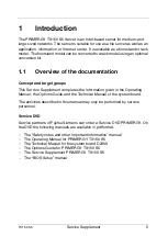
The Fujitsu PRIMERGY TX150 S5 is a reliable and efficient server designed for small businesses. Ensure optimal performance and smooth operation by accessing the comprehensive Operating Manual. Download the easy-to-follow manual for free from our secure website, empowering you to make the most of your server's capabilities.
Share
Download


Reviews:
No comments
Related manuals for PRIMERGY TX150 S5

HFAS1-XS20U
Brand: I-O DATA Pages: 49

BS-GS2008P
Brand: Buffalo Pages: 2

SUPERSERVER 5017C-MF
Brand: Supero Pages: 96

Palcare PAL-211401
Brand: PalatiumCare Pages: 64

eServer xSeries 335 Type 8676
Brand: IBM Pages: 178

DPR-2000
Brand: D-Link Pages: 40

PRIMERGY TX2550 M4
Brand: Fujitsu Pages: 563

NetVisor UNUM High Capacity Appliance
Brand: Arista Pages: 81

StorageWorks E Series
Brand: HP Pages: 8

StorageWorks 9000s NAS
Brand: HP Pages: 7

StorageWorks NAS e7000 v2
Brand: HP Pages: 2

StorageWorks NAS e7000 v2
Brand: HP Pages: 70

StorageWorks 600 All-in-One
Brand: HP Pages: 58

StorageWorks All-in-One SB600c - Storage Blade
Brand: HP Pages: 60

XH628 V5
Brand: Huawei Pages: 2

X6800
Brand: Huawei Pages: 52

V100R002C01
Brand: Huawei Pages: 122

U-SYS MRS6100
Brand: Huawei Pages: 131


