

10007825 REV. B ASD-120 2.0 INST. 10-15
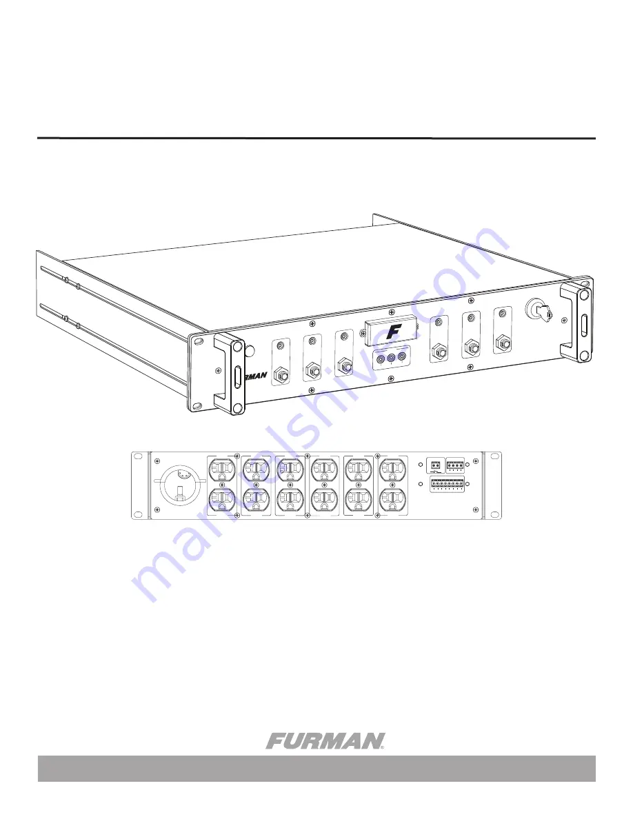
ASD-120 2.0
OWNER’S MANUAL
SIX CHANNEL SEQUENCING POWER DISTRIBUTION
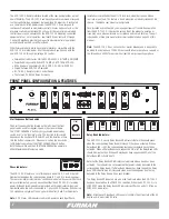
START
SEQUENCE
REMOTE
DLY
ADJ
DELAY A DELA
Y B
DELA
Y C
PHASE
X Y Z
DELAY D DELA
Y E
DELA
Y F
OFF ON
1 2 3 4 5 6 7
ALWAYS ON
ALWAYS OFF
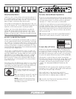
ASD-120 2.0
120 AMP POWER SEQUENCER
(SEE COVER PLA
TE)
INPUT 120 / 3Ø, 208 / 240 VAC
14400 WATTS – 120 AMPS MAX
20A MAX
DELAY A
20A MAX
DELAY B
20A MAX
DELAY C
20A MAX
DELAY D
20A MAX
DELAY E
20A MAX
DELAY F
FORCE OFF
DELAY OUTPUTS
REMOTE
NC A B C D E F NO
12V STAT REM GND
WARNING! ELECTRIC SHOCK HAZARD. CONNECTION OF A POWER
INPUT CABLE TO THIS DEVICE AND TO A POWER SOURCE MUST BE
DONE BY QUALIFIED PERSONNEL ONLY.
DANGER: MANIPULER SEL ON LES INSTRUCTIONS DU
FABRICANT ET CONFIER LA MAINTENANCE A UN T
ECHNICIEN QUALIFIE
DRY RELAY CONTACTS - RATING 48V / 1 AMP


