background image

OFS


Installation Instructions 

for  Slimbox 24 Fiber 

Indoor Enclosure 


8/3/2016 


 This document describes the assembly instructions for the SlimBox-V, Indoor Enclosure – 24 
fiber. 


Summary of Contents for OFS Slimbox 24

Page 1: ...OFS Installation Instructions for Slimbox 24 Fiber Indoor Enclosure 8 3 2016 This document describes the assembly instructions for the SlimBox V Indoor Enclosure 24 fiber...

Page 2: ...ISSUE DATE 8 5 2016 pg 1 Contents Contents 1 1 Products 2 2 Wall Installation Instructions 2 3 Installation Type Fan out 3 4 Installation Type Splitter 6 5 Installation Type Splice Tray 11 6 Installa...

Page 3: ...Use the drill template to mark the location of the mounting holes for the enclosure 3 Use a 3 16 inch approx 5mm drill bit to drill inch 19mm deep holes for the wall anchors Insert the wall anchors f...

Page 4: ...g the cables from the bottom retainer and work your way up to the top one Don t put the holding plate on back yet 3 Plug the cable connectorized ends SC UPC into the adapters Match the adapter number...

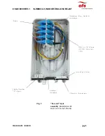
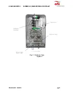
Page 5: ...LOSURE 24F ISSUE DATE 8 5 2016 pg 4 MPO to 12 Fiber SC UPC Fan Out 2X Base Cable Anchor L Brkt Adapter Mtg Brkt w adapt Rubber Grommet Plastic Retainer Holding Plate Fig 1 Fan out style assembly insta...

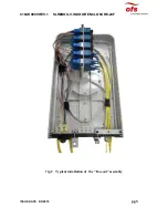
Page 6: ...C16AK0009 REV 1 SLIMBOX V INDOOR ENCLOSURE 24F ISSUE DATE 8 5 2016 pg 5 Fig 2 Typical installation of the Fan out assembly...

Page 7: ...ion consists of 4 fiber input cable conectorized with SC APC connectors up to four 4 PLC 1 32 splitters and up to 128 fiber distribution cable or cables connectorized with and 16 MPO Female 8 Fiber co...

Page 8: ...ties c Metal adapter bracket with SC and adapters d One up to four order dependent ruggedized splitter housings each containing one 1 32 PLC splitter The splitter input fiber is connectorized with a...

Page 9: ...he slack management spool and the splice trays to manage fiber extra length 5 Plug the spliced pigtail SC APC ends into designated SC APC adapters located in the adapter bracket to mate with the split...

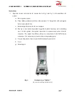
Page 10: ...C16AK0009 REV 1 SLIMBOX V INDOOR ENCLOSURE 24F ISSUE DATE 8 5 2016 pg 9 Adapter bracket Splitter Fig 5 Enclosure Type Splitter Splice tray Entry Exit Port 3X...

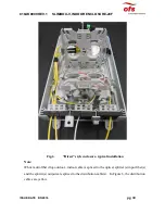
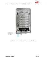
Page 11: ...g 10 Fig 6 Direct style enclosure typical installation Note White multi fiber drop outdoor indoor cable is spliced to the optical splitter s input fiber s and the splitter s outputs are spliced to the...

Page 12: ...e Tray This type of installation provides ten splice trays Each splice tray can accommodate 12 splice protectors or splitters No optical connector or adapters are used Drop and drop cables are secured...

Page 13: ...ll contain a Fiber organizer b Three rubber grommets with tree cable retainers L shape brkt with rectangular holes to pass plastic ties c Ten 10 pivoting Splice trays to hold splice protectors note th...

Page 14: ...le aramid yarn L bracket and cable ties to restrain the cable If you use a cable with a strength member use the anchor brkt to restrain the cable You may move the anchor bracket to lower part of the e...

Page 15: ...C16AK0009 REV 1 SLIMBOX V INDOOR ENCLOSURE 24F ISSUE DATE 8 5 2016 pg 14 Fig 9 Securing cable to L bracket enclosure type Splice Aramid yarn attached to L brkt...

Page 16: ...le of holding six splitters or twelve splice protectors Usually first two trays contain splitters and splice protectors and the remaining eight hold only splice protectors The splices are made between...

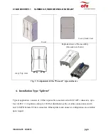
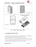
Page 17: ...C16AK0009 REV 1 SLIMBOX V INDOOR ENCLOSURE 24F ISSUE DATE 8 5 2016 pg 16 Cover Cover back view Assy Top view Exploded view of the assembly Fig 11 Components Enclosure type Splice w o mounting kit...

Page 18: ...ameter leave the enclosure through the port having 5 plastic retainers It is important to not use the cables having diameter outside of the 1 6 2 0 mm range since it may result in the cable damage and...

Page 19: ...emove the holding plate to loosen up the plastic retainers Lay down distribution 1 6 to 2 mm diameter cables in the retainer s grooves Assemble approximately six 6 cable assemblies per retainer Start...

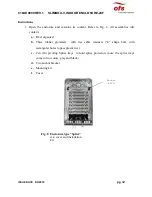
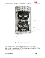
Page 20: ...R ENCLOSURE 24F ISSUE DATE 8 5 2016 pg 19 Fig 12 Enclosure Installation type Direct w o cover and mounting kit Strain member anchor brkt Adapter plate with adapters Splice Tray Fiber organizer Plastic...

Page 21: ...sufficient to install in certain conditions OFS reserves itself the right to make improvements enhancements or changes to the products without prior notification including technical data and other inf...

Reviews: