background image

www.furuno.com

All brand and product names are trademarks, registered trademarks or service marks of their respective holders.

Installation Manual

FISH FINDER/ HI-RES FISH FINDER/

FISH SIZE INDICATOR

Model 

FCV-1900/B/G

(Product Name: FISH FINDER)

SAFETY INSTRUCTIONS ................................................................................................ i
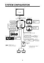
SYSTEM CONFIGURATION ........................................................................................... ii
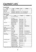
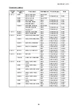
EQUIPMENT LISTS........................................................................................................ iii

1. MOUNTING................................................................................................................. 1

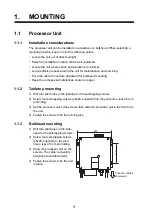
1.1 Processor Unit ......................................................................................................................1
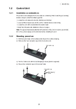
1.2 Control Unit ...........................................................................................................................2
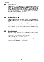
1.3 Transducer............................................................................................................................3
1.4 External Monitor....................................................................................................................3
1.5 Interface Unit.........................................................................................................................3
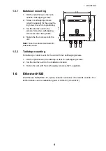
1.6 Ethernet HUB........................................................................................................................4
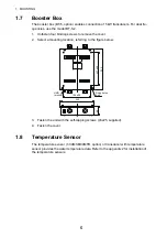
1.7 Booster Box ..........................................................................................................................5
1.8 Temperature Sensor .............................................................................................................5

2. WIRING....................................................................................................................... 6

2.1 Interconnection .....................................................................................................................6
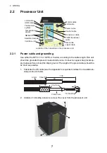
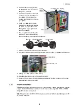
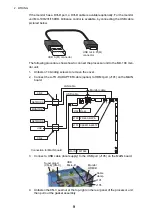
2.2 Processor Unit ......................................................................................................................7
2.3 Interface Unit.......................................................................................................................12
2.4 Net Sonde ...........................................................................................................................15
2.5 Ethernet HUB......................................................................................................................16
2.6 Booster Box ........................................................................................................................16
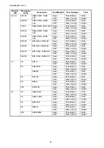
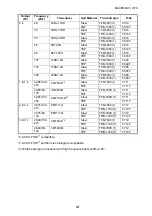
2.7 Input/Output Sentences ......................................................................................................17

3. INITIAL SETTINGS................................................................................................... 18

3.1 Installation Menu.................................................................................................................18
3.2 Monitor Setting....................................................................................................................19
3.3 Transducer Setting..............................................................................................................20
3.4 NMEA Port Setting..............................................................................................................23
3.5 Communication Port Monitor ..............................................................................................24
3.6 Calibration Setting...............................................................................................................25
3.7 Stabilization Setting ............................................................................................................26
3.8 Telesounder Setting............................................................................................................27
3.9 Reset to Default Setting ......................................................................................................27
3.10 Upgrading to FCV-1900B/1900G........................................................................................27

APPENDIX 1 JIS CABLE GUIDE .............................................................................AP-1
APPENDIX 2 INSTALLATION OF TEMPERATURE SENSORS .............................AP-2
PACKING LISTS ......................................................................................................... A-1
OUTLINE DRAWINGS ................................................................................................ D-1
INTERCONNECTION DIAGRAM ................................................................................ S-1

Summary of Contents for FCV-1900/B/G

Page 1: ...Box 5 1 8 Temperature Sensor 5 2 WIRING 6 2 1 Interconnection 6 2 2 Processor Unit 7 2 3 Interface Unit 12 2 4 Net Sonde 15 2 5 Ethernet HUB 16 2 6 Booster Box 16 2 7 Input Output Sentences 17 3 INITI...

Page 2: ...d fuse Use of an incorrect cable and fuse can damage the equipment and cause fire Mandatory Action Prohibitive Action WARNING CAUTIO CAUTION Warning Caution Indicates a potentially hazardous situation...

Page 3: ...B 002 Control Unit FCV 1902 Temperature Sensor T 04MSB T 04MTB Booster Box BT 5 Transducer Transducer Ethernet HUB HUB 101 Interface Unit FCV 1903 Network Fish Finder DFF series BBDS1 Telesounder TS 8...

Page 4: ...sensor T 04MSB 000 026 893 Thru hull mount T 04MTB 000 026 894 Transom mount Rectifier RU 1746B 2 000 030 439 AC DC power supply unit PR 240 000 013 632 Ethernet HUB HUB 101 000 011 762 Booster box BT...

Page 5: ...1100 2 T 693F 82 200 82B 35R 200B 8 8B Steel TFB 7000 2 T 649 FRP TRB 1100 2 T 649F 88 200 88B 10 200B 8 8B Steel TFB 7000 2 T 649 FRP TRB 1100 2 T 649F 2 k 3 k 28 150 28BL 18 150B 12H Steel TFB 7000...

Page 6: ...1100 2 T 685F 88 200 88F 126H 200B 12H Steel TFB 7000 2 T 685 FRP TRB 1100 2 T 685F 1 k 28 28F 8 Steel TFB 5000 1 T 604 FRP TRB 1000 1 T 604F 50 50B 6 6B Steel TFB 5000 1 T 605 FRP TRB 1000 1 T 605F 5...

Page 7: ...649 FRP TRB 1000 1 T 649F 150 150B 12H Steel TFB 5000 1 T 685 FRP TRB 1000 1 T 685F 200 200B 12H Steel TFB 5000 1 T 646 FRP TRB 1000 1 T 646F 1 k 1 k 42 65 130 210 CM265LH 3 Steel TFB 7000 1 T 711 FR...

Page 8: ...fe distances shown on page i 1 1 2 Tabletop mounting 1 Drill four pilot holes in the tabletop for the self tapping screws 2 Screw four self tapping screws 5x20 supplied into the pilot holes leave 5 mm...

Page 9: ...ideration for cable length Keep the compass safe distances shown on page i Note The ground terminal is attached to the bottom of the unit Connect a ground wire IV 1 25 sq local supply to the terminal...

Page 10: ...vailable for external monitor The external monitor must have the following specifica tions Video signal HDMI or DVI D Single link DVI D requires optional cable assembly Resolution SXGA 1280 x 1024 SXG...

Page 11: ...rews to fix the unit Note Face the cables downward for bulkhead mount 1 5 2 Tabletop mounting For tabletop or deck mount fix the unit with four self tapping screws 1 Drill four pilot holes in the tabl...

Page 12: ...t a mounting location referring to the figure below 3 Fasten the unit with the self tapping screws 5x25 supplied 4 Fasten the cover 1 8 Temperature Sensor The temperature sensor T 04MSB 04MTB option o...

Page 13: ...V 1902 Ethernet HUB HUB 101 Ethernet HUB HUB 101 FCV 1903 INTERFACE UNIT PWR Interface unit FCV 1903 Junction box RJB 002 Network fish finder DFF1 DFF3 BBDS1 Booster box BT 5 Telesounder TS 80M2 TS 71...

Page 14: ...hort as possible 1 Fabricate the JIS cable see the Appendix for equivalent cables if not available lo cally as shown below 2 Unfasten 14 binding screws to remove the cover from the processor unit Loca...

Page 15: ...eck the cable and the terminal polarities then connect the cable to the terminal 9 Clamp the cable with the cable clamp 10 Reattach the filter cover to the power terminal 11 Fasten the unit cover When...

Page 16: ...nnect the A TO D ADAPTER cable option to HDMI port J101 on the MAIN board 3 Connect a USB cable local supply to the USB port J105 on the MAIN board 4 Unfasten the CN 3 seal nut at the top right on the...

Page 17: ...the following figure 9 Close the cover Waterproofing the connectors Wrap the connectors with vulcanizing tape and then wrap with vinyl tape Bind the tape ends with a cable tie Super gland Seal nut Gas...

Page 18: ...N 2 on the right side of the connector panel 3 Connect the transducer cable to the WAGO connector referring to the intercon nection diagram at the back of this manual For dual frequency connections co...

Page 19: ...MJ A6SPF0003 is used Connect the cables to the processor unit via the CN 10 or CN 11 port For con nection to the external equipment see the equipment s installation manual Temperature sensor Connect t...

Page 20: ...s J1 and J2 6 Adjust the cable length inside the interface unit place the gasket assembly in the seal nut and then fasten them both securely 7 Unfasten the seal nut at the left bottom of the pro cesso...

Page 21: ...11 Close the inner case and outside cover of the interface unit 12 Close the cover of the processor unit 13 The connections for telesounders TS 7100 and TS 80 MK 2 are different Con nect them to the...

Page 22: ...nterconnection diagram 5 Reattach the WAGO connector 6 Unfasten the screws on the cable clamp then fix the cables with the cable clamp 7 Close the cover of the processor unit 8 Fit a connector to the...

Page 23: ...ix the cable 7 Connect another LAN cable to J4 connector on the CTRL board and then fasten the cable to the cable clamp with a cable tie 8 Fasten the seal nut to fix the cable after the cable length i...

Page 24: ...the following NMEA data sentences Data I O Sentence Time position Input GNS GGA GLL Course over the ground COG and speed over the ground SOG Input VTG Water speed and heading Input VHW Water depth Out...

Page 25: ...lect unit desired then push the knob to set Similarly set the unit for ship s speed water temperature and fish size 4 Rotate the ENTER knob to select Display Resolution then push the knob to show the...

Page 26: ...then push the knob 6 The processor unit is restarted automatically The restart takes approx 5 minutes Setting Sounder Display Measurement Alarm Data System Service Bottom Search Deference Gain Deferen...

Page 27: ...5 Select XDCR type at HF XDCR select Confirm that the high freq transducer is connected to the HF port CAUTION Set the transducer data properly Wrong data setting may damage the transducer and void th...

Page 28: ...onnected set Net sonde to On 13 After completion of setting rotate the ENTER knob to select Save Setting then push the knob Select Yes and push the knob to apply the settings Transducer lists The tabl...

Page 29: ...is automatically set however it can be entered manually with Band width 6 Set the LF transducer similarly Single frequency setting When using only one transducer connect the transducer to either the h...

Page 30: ...e 600 4800 38400 bps for NMEA and 600 1200 2400 4800 bps for CIF Start Bit 1 bit fixed Data Length 8 bit fixed Stop Bit 1 bit fixed Parity none fixed Clear Window Refresh the information on the commun...

Page 31: ...rt monitor display 6 To turn off the port monitor display press the MENU ESC key and select Exit then push the ENTER knob 7 Rotate the ENTER knob to select Yes then push the knob The port monitor is c...

Page 32: ...0 4 m default value or more set the transmission line width with Zero Line Area as below Zero Line Area This feature adjusts the transmission line so that the transmission line disappears when the me...

Page 33: ...ue set here stabilization is stopped and the stabilization icon at the top of the screen disappears However Sta bilization is kept On When heaving is once again less than the value set here sta biliza...

Page 34: ...de key place an order with your local FURUNO dealer The upgrade procedure requires a USB flash memory USB cable micro B and type A connectors attached and USB type A conversion adapter female to femal...

Page 35: ...window 12 Press the MENU ESC key several times to close the menu 13 Turn the processor unit off and then remove the USB flash memory Upgrade system Yes No Press the camera icon key 3 times to capture...

Page 36: ...CY 4 0 75mm2 1 11mm 17 7mm TTYCY 4S 0 75mm2 1 11mm 21 1mm TTYCY 4SLA 0 75mm2 1 11mm 19 5mm TTYCYS 1 0 75mm2 1 11mm 12 1mm TTYCYS 4 0 75mm2 1 11mm 18 5mm TTYCYSLA 1 0 75mm2 1 11mm 11 2mm TTYCYSLA 4 0 7...

Page 37: ...ull If there is any petroleum residue inside the hull remove it with either mild household detergent or a weak solvent alcohol b f di Record the information found on the cable tag for future reference...

Page 38: ...interference separate the transducer cable from other electrical wiring and the engine Coil any excess cable and secure it in place with cable ties to prevent damage 2 Refer to the instrument owner s...

Page 39: ...ketones can attack many plastics possibly damaging the sensor Reapply anti fouling paint every 6 months or at the beginning of each boating season Replacement Sensor Parts The information needed to or...

Page 40: ...low for optimal product performance and to reduce the risk of property damage personal injury and or death WARNING Always wear safety goggles and a dust mask when installing WARNING Below the waterlin...

Page 41: ...encil 8 Using a 3mm or 1 8 drill bit drill a pilot hole s at the marked locations 10mm 3 8 deep 9 Apply marine sealant to the threads of the screw s to prevent water from seeping into the transom 10 F...

Page 42: ...4 26 10 1 3 6 70 6 241 5514 70 6 8 52 4 2 465 52 4 2 465 52 056 6 10 6 4 5 056 6 10 6 4 5 2 1 7 06 12 4 614 5 07 1 056 6 10 07 2 A 1 1 8 0 1 7 6 0 5 4 26 10 1 3 6 70 6 10641 70 6 8 056 6 10 6 4 5 056...

Page 43: ...56 6 10 6 4 5 55 5 056 6 10 6 4 5 2 2 A 3 1 01 6 2 2 176 0 0 3 6 4 4 5 01 5 4 26 105 056 6 10 6 4 5 1 5 6 22 0 5 4 9 575 1 01 6 8 6 1 01 05 105 0 4 9 0 14 4 4 0 10 691 6 2 5 0 1 5 56 14 0 6 6 19 4 241...

Page 44: ...4 9 0 14 4 4 0 10 691 6 2 5 0 1 5 56 14 0 6 6 19 4 241 7 6 5 22 0 2 1 6 722 4 241 7 6 37 6 5 6 5 2 A 5 1 01 6 2 2 176 0 0 3 6 4 4 5 01 5 4 26 105 056 6 10 6 4 5 5 6 22 0 5 4 9 575 1 01 05 105 0 4 9 0...

Page 45: ...2 4 8 5 52 4 914 0 37 06 6 4 4 5 1 01 1 01 2 5 2 01 52 4 2 465 56 14 7 5 5 65 2 4 8 55 6 2 01 1 1 8 55 67 75 4 5 0 74701 64 1 6 9 01 05 105 0 4 9 0 14 4 4 0 10 2 691 6 2 5 0 1 5 56 14 0 6 6 19 4 241...

Page 46: ...D 1 14 Apr 2015 H MAKI...

Page 47: ...D 2 15 Apr 2015 H MAKI...

Page 48: ...D 3 15 Jan 2015 H MAKI...

Page 49: ...1 8 O 61 8 O 8 241 55 4 70 6 8 52 6 6 0 4 4 5 52 0 4 4 5 52 0 0 0 5 6 2 6 2A 8 5 A 659A0 8A0 8A2 659A2 0 6 6 52 5 6 6 1 2 55 6 6 5 O 6 5 6 6 6 2 5 0514 52 O 6 6 0 0 0 40 6 40 37 2 06 52 6 59 9 6 40 4...

Page 50: ......

Page 51: ......

Page 52: ...lemental chlorine free FURUNO Authorized Distributor Dealer 9 52 Ashihara cho Nishinomiya 662 8580 JAPAN A APR 2015 Printed in Japan All rights reserved B MAY 22 2015 Pub No IME 23860 B TAYA FCV 1900...

Reviews: