background image

www.furuno.com

All brand and product names are trademarks, registered trademarks or service marks of their respective holders.
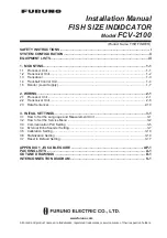
Installation Manual

FISH SIZE INDIDCATOR

Model

 FCV-2100

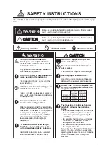
SAFETY INSTRUCTIONS ................................................................................................ i
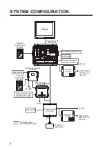
SYSTEM CONFIGURATION ........................................................................................... ii
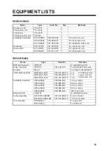
EQUIPMENT LISTS........................................................................................................ iii

1. MOUNTING..............................................................................................................1-1

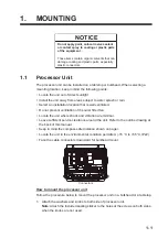
1.1 Processor Unit ...................................................................................................................1-1
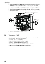
1.2 Transceiver Unit.................................................................................................................1-2
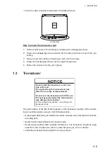
1.3 Transducer.........................................................................................................................1-3
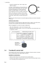
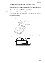
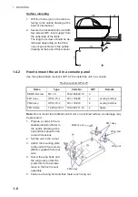
1.4 Trackball Control Unit ........................................................................................................1-4
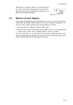
1.5 Monitor (Local Supply) .......................................................................................................1-7

2. WIRING....................................................................................................................2-1

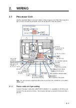
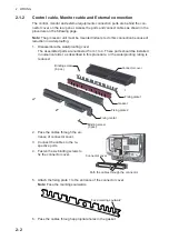
2.1 Processor Unit ...................................................................................................................2-1
2.2 Transceiver Unit.................................................................................................................2-6
2.3 Data Sentences ...............................................................................................................2-14

3. INITIAL SETTINGS..................................................................................................3-1

3.1 How to Set the Language and Measurement Unit .............................................................3-1
3.2 How to Set the Service Menu ............................................................................................3-2
3.3 Communication Port Setting ..............................................................................................3-5
3.4 External Echo Sounder Setting..........................................................................................3-7
3.5 Calibration Setting............................................................................................................3-10
3.6 Stabilization Setting .........................................................................................................3-14
3.7 Reset to Default Setting ...................................................................................................3-17

APPENDIX 1 JIS CABLE GUIDE .............................................................................AP-1

PACKING LISTS ......................................................................................................... A-1

OUTLINE DRAWINGS ................................................................................................ D-1

INTERCONNECTION DIAGRAM ................................................................................ S-1

(Product Name: FISH FINDER)

Summary of Contents for FCV-2100

Page 1: ...ball Control Unit 1 4 1 5 Monitor Local Supply 1 7 2 WIRING 2 1 2 1 Processor Unit 2 1 2 2 Transceiver Unit 2 6 2 3 Data Sentences 2 14 3 INITIAL SETTINGS 3 1 3 1 How to Set the Language and Measureme...

Page 2: ...7KH SDSHU XVHG LQ WKLV PDQXDO LV HOHPHQWDO FKORULQH IUHH 85812 XWKRUL HG LVWULEXWRU HDOHU VKLKDUD FKR 1LVKLQRPL D 3 1 35 3ULQWHG LQ DSDQ OO ULJKWV UHVHUYHG 1 3XE 1R 0 0 9...

Page 3: ...in the worst case result in loss of the transducer Mandatory Action Prohibitive Action WARNING CAUTIO CAUTION Warning Caution Indicates a potentially hazardous situation which if not avoided could res...

Page 4: ...t Satellite Compass Net Sonde 24 VDC 24 VDC 24 VDC 24 VDC 100 110 220 230 VAC 1 50 60 Hz 100 110 220 230 VAC 1 50 60 Hz Rectifier PR 62 Rectifier PR 62 Transceiver Unit FCV 2102 Transducer FCV 2103 US...

Page 5: ...USB device server UDS 001 w Installation guide Flush mount kit OP14 70 001 132 700 For trackball control unit Rectifier PR 62 For 100 110 220 230VAC LAN cable assembly MOD Z072 020 001 167 880 10 2 m...

Page 6: ...EQUIPMENT LISTS iv This page is intentionally left blank...

Page 7: ...this manual Keep in mind the compass safe distance shown on page i Locate the unit in the environmental condition permitted 15 C to 55 C IP22 Face the cable connectors downward for bulkhead mount How...

Page 8: ...t down ward or to the front 5 Fasten the screws to secure the unit in place 1 2 Transceiver Unit The transceiver unit can be installed on a tabletop or bulkhead When selecting a mounting location keep...

Page 9: ...ounting location keep in mind following points A place least affected by air bubbles should be selected since turbulence blocks the sounding path Select a place least influenced by engine noise Select...

Page 10: ...operator s manual 1 4 Trackball Control Unit The trackball control unit can be installed on a tabletop or flush mounted in a console Flush mounting requires the optional flush mount kit Installation...

Page 11: ...cessor unit Keep in mind the compass safe distance shown on page i 1 4 1 How to mount the unit on a desktop You can install the unit flat on the desktop or use the fixing plate for a tilted installati...

Page 12: ...unit on a inclined surface as drainage may be prevented 1 Prepare a cutout in the in stallation location Refer to the outline drawing at the back of this manual for the cutout dimensions 2 Set the un...

Page 13: ...190HD Refer to the monitor s manual for installation You can use an after market monitor which has specifications as follows Video signal DVI D single link monitor cable option Resolution XGA 1024 x 7...

Page 14: ...1 MOUNTING 1 8 This page is intentionally left blank...

Page 15: ...plied to 24VDC power Connect the ground wire IV 2sq local supply between ground terminal and ship s ground To power source rectifier FCV 2102 HUB 101 DVI D D S LINK option GND Ground to hull 24VDC MJ...

Page 16: ...ered from 1 to 4 These parts should be installed in numerical order as described in this procedure or the waterproofing rating is reduced 2 Pass the cables through the en trance of connector cover 3 C...

Page 17: ...tor or equivalent XGA after market monitor can be connected as an external monitor Connect the monitor to the correct port depending on whether the monitor has analog or digital output Digital DVI D2...

Page 18: ...HD or UXGA or WUXGA In order to maintain waterproofing use a DVI D D S LINK cable to connect the main monitor to the DVI D1 port Note The processor unit must be mounted indoors to do this connection...

Page 19: ...ding screws to fix the boot cover 6 Set the fixing plate to the entrance of boot cover 7 Pass the cable through the hole in gasket Be aware of the gasket orientation The slit must be on the right hand...

Page 20: ...e can cause water ingress 2 2 Transceiver Unit Use the specified cable to connect the transceiver unit to external equipment Waterproofing sheet Cable fixing plate Binding screw 2 pcs Cable ties for f...

Page 21: ...s head screw driver How to connect the transducer cable 1 Fabricate the cable end as follows Note To avoid interference do not change the specified length of fabrication 2 Unfasten six screws to remov...

Page 22: ...igure at step 3 WAGO connecter WAGO connecter Terminal opener Terminal opener Transducer Seal Claw Seal nut How to attach wires to the WAGO connector Push downward Terminal opener WAGO connector Wire...

Page 23: ...100 mm distance from the super gland Fix the cable with cable saddles 3 pcs Connect the WAGO connector to TB1 Terminal opener Secure the shield and drain wire terminal lugs with a screw Position the...

Page 24: ...nut of NETWORK port and disassemble the seal assembly 3 Dismantle the seal assembly as shown below 4 Pass the cable into the seal nut and seal assembly then insert the cable into the unit through the...

Page 25: ...l nut leaving approx 2 mm gap between the seal nut and super gland fixing nut 9 Close the cover of the transceiver unit Fabricating LAN cables Fabricate the LAN cables when using the optional armored...

Page 26: ...PANDUIT CORP crimp the modular plug Finally check the plug visually Expose inner vinyl sheath Remove the outer sheath by approx 25 mm Be careful not to damage inner shield and cores Fold back the shi...

Page 27: ...rd 4 Unfasten the seal nut of EXT KP port and disassemble the seal assembly Remove a seal grommet to pass the cable 5 Pass the cable into the seal nut and seal assembly then insert the cable into the...

Page 28: ...he cover of the transceiver unit 2 3 Data Sentences This equipment can input output the following NMEA data sentences Data I O Sentence Time position Input GNS GGA GLL Course over the ground COG and s...

Page 29: ...eft top when the InstantAccess bar is hidden To hide the InstantAccess bar press the but ton or right click of trackball control on anywhere of the screen 3 Select the Advanced Settings icon from the...

Page 30: ...from the main monitor 3 2 1 How to Display the Service Menu 1 Select the Advanced Settings icon from the InstantAccess bar and se lect the Advanced Setting icon from the expanded menu bar 2 Select Se...

Page 31: ...B For main monitor settings go to step 6 For sub monitors go to step 3 3 Select the sub monitor position left right from the Sub Monitor Position menu 4 Select the sub monitor display resolution from...

Page 32: ...enu 3 2 4 Transducer setting You can increase the accuracy of your fish finder by adjusting transducer parameters Adjust the parameters as follows 1 Select the Shared Settings on the Service menu 2 Se...

Page 33: ...ings icon from the InstantAccess bar and se lect the Advanced Setting icon from the expanded menu bar 2 Select Tests from the System menu The Tests menu appears on the right hand side of the window 3...

Page 34: ...600 or 115200 bps however data from the navigation equipment cannot be received 8 For NMEA data type select output data from Depth Temperature Hardness or Fish size You can select more than one datum...

Page 35: ...inder are either a DFF3 or a DFF1 UHD Set the transducer parameters from the main monitor as belows 1 Select the Advanced Settings icon from the InstantAccess bar and se lect the Advanced Settings ico...

Page 36: ...for DFF3 1 Select the TX Triggering to On to enable the KP control with DFF3 Note The main transceiver s TX trigger setting should be Off while this ex ternal TX trigger is set On 2 Select the Settin...

Page 37: ...the TD ID information is not received you are informed that the transducer could not be set and to retry setting the transducer Click the No button to restart the equipment 8 Click the OK button to r...

Page 38: ...the transducer type from menu for DFF3 or set the transducer parameters for DFF1 UHD Refer to the procedure for paragraph 3 4 1 8 Select OK to close the menu 3 5 Calibration Setting The calibration m...

Page 39: ...sappears when the Zero Line Rejector is turned on For long tail in crease the value If the transmission line does not disappear lower the TX power 1 4 to 3 0 m Zero line fill Turn off to see fish echo...

Page 40: ...the absorption coefficient 0 0 to 60 0 dB Temperature Available when Absorption Coefficient is set to Auto Select the input source of the water temperature used for automatic calcu lation of absorptio...

Page 41: ...ibration parameters referring to the table below Gain stabilization LF HF Set the antenna position for the Satellite Compass 50 to 50 TD fore aft port stbd Distance m from antenna to transducer on the...

Page 42: ...ystem and external system transducers when the External sounder is set Off 1 Select the Advanced Settings icon from the InstantAccess bar and se lect the Advanced Setting icon from the expanded menu b...

Page 43: ...re aft line Enter a positive value for a fore side transducer a negative value for an aft side trans ducer 100 0 to 100 0m TD port stbd Distance m from antenna to transducer on the port stbd line En t...

Page 44: ...d er is set On 1 Move the cursor onto the sub monitor and right click on the screen The setting menu for external sounder appears 2 Select Stabilization from the list on menu The Stabilization menu ap...

Page 45: ...ice from the menu then press and hold the OK button for approxi mately ten seconds The Shared Settings menu appears 3 Select Restore Default Settings at the left bottom corner of the window The messag...

Page 46: ...3 INITIAL SETTINGS 3 18 This page is intentionally left blank...

Page 47: ...CY 4 0 75mm2 1 11mm 17 7mm TTYCY 4S 0 75mm2 1 11mm 21 1mm TTYCY 4SLA 0 75mm2 1 11mm 19 5mm TTYCYS 1 0 75mm2 1 11mm 12 1mm TTYCYS 4 0 75mm2 1 11mm 18 5mm TTYCYSLA 1 0 75mm2 1 11mm 11 2mm TTYCYSLA 4 0 7...

Page 48: ...7 7 21 0 7 5 6 0 66 0 0 63 211 725 66 0 3 5 3 5 167 7 21 0 7 5 6 3 7 53522 29 5 66 0 3 7 53522 29 5 66 0 3 2 80 17 23 5 725 6 0 18 20 167 7 21 0 18 0 A 1 6 9 1 0 2 8 7 1 6 5 37 21 2 4 7 81 7 75 16 9 5...

Page 49: ...A 3 1 01 6 6 2 2 176 0 0 3 6 4 4 5 01 5 4 26 105 056 6 10 6 4 5 9 5 17 4 5 4 9 9 6 5 9 1 01 67 52 4 1 01 5 6 22 0 5 4 9 575 1 01 6 8 0 1 01 05 105 0 4 9 0 14 4 4 0 10 691 6 2 5 0 1 5 56 14 0 6 6 19 4...

Page 50: ...8 9 5 2 12 5 03 21 8 9 0 2 12 233 5 675 3 52 6 2 12 0 16 216 1 5 1 25 5 5 1 21 0 A 5 1 01 6 2 2 176 0 0 3 6 4 4 5 01 5 4 26 105 5514 5 0 4 9 5 4 41 5 1 01 0 0 5 0 1 01 0 01 0 1 01 75 1 01 05 105 0 4 9...

Page 51: ...4 0 10 2 691 6 2 5 0 1 5 56 14 0 6 6 19 4 241 7 6 5 22 0 2 1 6 722 4 241 7 6 37 6 5 6 5 A 7 1 01 6 2 52 6 01 0 1 2 46 176 0 9 01 14 2 4 5 6 2 4 8 5 52 4 914 0 37 06 6 4 4 5 1 01 1 01 2 5 2 01 52 4 2 4...

Page 52: ...16 Nov 2015 H MAKI 16 Nov 2015 H MAKI...

Page 53: ...17 Nov 2015 H MAKI 17 Nov 2015 H MAKI...

Page 54: ...26 Feb 2016 H MAKI 26 Feb 2016 H MAKI...

Page 55: ...17 Nov 2011 Y NISHIYAMA 17 Nov 2011 Y NISHIYAMA...

Page 56: ...17 Nov 2011 Y NISHIYAMA 17 Nov 2011 Y NISHIYAMA...

Page 57: ...17 Nov 2011 Y NISHIYAMA 17 Nov 2011 Y NISHIYAMA...

Page 58: ...8 Mar 2016 H MAKI...

Page 59: ...87 1 6 86 B6 750 9 9 VT 7 8 8 6 9 6 59 5 8 6 8 6 35 3 9 VT 75 21752 81 7 9 5 7 5 35 9 VT 75 16 8 5 B7 B B7 B B7 B B7 B B7 B B7 B B7 B B7 B P 7 8 5 33 51 51 5 25 6 7 P 7 16 8 5 9 75 16 9 5 81 7 9 7 3 6...

Reviews: