background image

FISH FINDER

FCV-627

OPERA

T

OR'S MANU

AL

www.furuno.com

B R I L L

GAIN

Summary of Contents for FCV-627

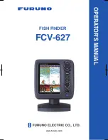
Page 1: ...FISH FINDER FCV 627 OPERATOR S MANUAL www furuno com B R I L L GAIN ...

Page 2: ...chlorine free FURUNO Authorized Distributor Dealer 9 52 Ashihara cho Nishinomiya 662 8580 JAPAN A OCT 2011 Printed in Japan All rights reserved Pub No OME 23820 A 00017552510 00017552510 DAMI FCV 627 00017552510 00017552510 0 0 0 1 7 5 5 2 5 1 0 ...

Page 3: ...is product according to local regulations for the disposal of industrial waste For disposal in the USA see the homepage of the Electronics Industries Alliance http www eiae org for the correct method of disposal How to discard a used battery Some FURUNO products have a battery ies To see if your product has a battery see the chapter on Maintenance Follow the instructions below if a battery is used...

Page 4: ...uver the vessel based on the depth indication alone Grounding can result Do not disassemble or modify the equipment Fire electrical shock or injury can result Use the proper fuse Use of an incorrect fuse can damage the equipment and can cause fire Do no turn on the equipment with the transducer out of water The transducer can be damaged The picture is not refreshed when picture advancement is stop...

Page 5: ...formance will be affected The following are guidelines for handling of the transducer cable Keep fuels and oils away from the cable Locate cable in a safe place Do not paint the cable The sheath of the cable is made of chloroprene rubber or polychloride vinyl For this reason do not paint the cable Do not turn on the equipment with the transducer out of water The transducer can be damaged Observe t...

Page 6: ...s 19 1 19 3 How to erase waypoints 19 1 19 4 How to set destination waypoint 20 1 20 Setting Up Nav Data Displays 20 1 20 1 Nav data displays 20 1 21 Menu Description 21 2 SYSTEM MENU 26 2 1 How to Display the System Menu 26 2 2 Range Menu 26 2 3 Key Menu 26 2 4 Language Menu 26 2 5 Units Menu 27 2 6 Calib Menu 27 2 7 Transducer Menu 28 2 8 Demo Menu 28 2 9 Tankenmaru Menu 28 3 MAINTENANCE TROUBLE...

Page 7: ...olor LCD in various colors according to echo strength The main features of the FCV 627 are Bright color LCD gives excellent readability even in broad daylight Waterproof construction permits installa tion on open bridge Automatic mode automatically adjusts the set to provide the best possible display from shallow to deep depths ACCU FISH feature provides estimate of fish length with fish size depe...

Page 8: ... Water temperature speed sensor ST 02MSB ST 02PSB Water temperature sensor T 02MSB T 02MTB T 03MSB 520 5PSD 520 5MSD 525 5PWD 525STID MSD 525STID PWD Transducer 12 24 VDC GPS Navigator External Equipment Radio Transmitter Radio transmitter of SHIMANO INC SHIMANO INC make display unit FCV 627 Display Unit Tankenmaru System Electric Relay ...

Page 9: ...Opens function key programming window 7 GAIN Push Opens Auto Gain setting window Rotate Manually adjusts gain 8 MODE Selects display mode 9 BRILL Short press Turns on power opens the Brill adjustment window Long press Turns off power How to remove the cover If you remove the display unit for desktop installation after an outing Pull down on the catch at the bottom of the cover and pull the cover t...

Page 10: ...ting window which is displayed for six seconds 2 Rotate the MODE knob again to select the display mode desired The screen re lated to the mode you selected appears 1 4 1 Single frequency display Low frequency 50 kHz The sounder uses ultrasound pulse signals to detect bottom conditions The lower the fre quency of the signal the wider the detection area Therefore the 50 kHz frequency is use ful for ...

Page 11: ...djust the range of the zoom dis play go to the Range menu see section 2 2 Note 2 To show or hide the zoom marker go to the Display menu Picture advance speed Display mode Range Gain Minute marker Each bar equals 30 sec Data box Color bar Depth Transmission line Fish Range scale Bottom AUTO_R G AF AUTO_R G AF LF LF x1 x1 0 0 0 0 15 5 kn 13 5 C 15 5 kn 13 5 C 0 20 40 60 80 0 20 40 60 80 48 6 48 6m m...

Page 12: ...sensor Two nav data displays are available Nav Data 1 or Nav Data 2 and you may select which to use on the Display menu The de fault settings are as follows NAV1 Two data display SPEED STW WIND NAV2 Four data display DEPTH TEMPERATURE TRIP METER ODOMETER You can display between two and four items in a nav data display and select the item and order to display them For details see section 1 20 NAV1 ...

Page 13: ...the ENTER key Note The range mode indication which ap pears at the top left corner may be turned on or off with Header Info on the Display menu For details see Header Info on page 23 1 6 How to Adjust the Gain How to select the gain adjustment mode The gain may be adjusted automatically Fishing or Cruising or manually In auto matic adjustment the range is automatically selected to display the bott...

Page 14: ... you selected Fishing or Cruising you can apply an offset to the gain at step 3 To apply no offset go to step 4 For Off do steps 4 and 5 3 Press W or X setting range 5 to 5 to apply an offset Press W to decrease the offset X to raise the offset 4 Press the ENTER key The new gain set ting is also applied to past echoes 5 For manual adjustment rotate the GAIN control to set the gain 0 0 to 10 1 7 Ho...

Page 15: ...instead of the ENTER key 7 To select another menu press the MENU ESC key or W The cursor yel low moves to the main menu 8 Press the MENU ESC key to close the menu Note Hereafter this manual replaces the in struction use S or T to select an item or change a value with select 1 9 How to Shift the Range The basic range and range shift together give you the means to select the depth you can see on the...

Page 16: ...peed to moni tor a smooth bottom Picture and picture advance speed 1 Open the menu select Sounder and press the ENTER key 2 Select Pic Advance and press the EN TER key Pic Advance setting window 3 Select picture advance speed desired and press the ENTER key 1 16 is the slowest speed and x4 is the fastest speed 1 16 means one scan line is pro duced every 16 transmissions Stop stops picture advancem...

Page 17: ...ff the interference rejector when no interference exists so as not to miss weak echoes from small targets 4 Press the MENU ESC key twice to close the window 1 12 How to Reduce Low Level Noise Low intensity speckles caused by sedi ments in the water or noise may appear over most of screen These speckles can be sup pressed by adjusting the Clutter Clutter appearance Note Clutter cannot be adjusted w...

Page 18: ... to close the window 1 14 A scope Display The A scope display shows echoes at each transmission with amplitudes and tone pro portional to their intensities on the right 1 3 of the screen The display shows strong echoes with strong amplitude weak echoes in weak amplitude Thus the A scope display is useful for estimating the kind of school of fish and bottom composition Note The A scope display is o...

Page 19: ...ds on fish species When the fish length differs between the in dicated length and the actual length you can compensate the difference on the Calib menu see section 2 6 ACCU FISH is inoperative when the zero line rejector is active High and low frequencies are alternately transmitted when ACCU FISH is active re gardless of mode selection A fish whose depth is shallower than 2 m or greater than 100 ...

Page 20: ...timated length of the fish Note To hide the fish symbol select Off at step 4 and press the ENTER key Note You can select which frequency display to show the fish symbols and fish information with Symbols Area on the ACCU FISH menu Dual Symbols and info shown on both HF and LF displays HF Symbols and info shown on HF dis play LF Symbols and info shown on LF dis play 1 15 3 Fish info 1 Open the menu...

Page 21: ... The 600 W transducers and triducers that support the bottom discrimination feature are 520 5PSD 520 5MSD 525 5PWD 525STID MSD 525STID PWD The high and low frequencies are alternate ly transmitted regardless of current display selection The TX interval is slower when this feature is active Operating environment Depth 16 to 328 ft Speed 10 knots or less The bottom discrimination feature uses the di...

Page 22: ...he water temperature is within inside alarm the alarm range set or under over out side alarm the range set The bottom type alarm alerts you when the bottom type rock sand mud gravel match es the bottom type selected Available when the bottom discrimination display is active The bottom alarm alerts you when the bot tom echo displayed in red or reddish brown is within the alarm range set z Navigatio...

Page 23: ...he ENTER key 7 Select desired alarm sound and press the ENTER key 8 Select Fish Type Temperature Bot tom Type or Bottom as applicable and press the ENTER key 9 Do one of the following according to the item selected at step 8 Fish Type 1 Select ACCU FISH Fish School Bottom Fish Only BL or Bottom and press the ENTER key For ACCU FISH go to step 2 For other choices go to step 6 2 Select From under Fi...

Page 24: ...ey 5 Enter the width for the alarm and press the ENTER key Bottom Type Select Rock Gravel Sand or Mud and press the ENTER key Bottom 1 Set Bottom to On and press the EN TER key 2 Select From and press the ENTER key 3 Set the starting depth and press the ENTER key 4 Select Span and press the ENTER key 5 Set the width of the alarm and press the ENTER key 10 Press the MENU ESC key to show the FIsh Sc...

Page 25: ...2 Select Inside or Outside as applica ble and press the ENTER key 3 Select Radius and press the ENTER key 4 Enter the alarm radius and press the ENTER key To disable the alarm select Off at 2 of step 3 1 18 FUNC Key The FUNC key provides for one touch call up of desired function setting window 11 items are available picture advance shift interfer ence clutter color erase white line white marker WP...

Page 26: ...Press the TrackPad to set the cross cur sor where desired Picture advancement is stopped until step 3 is completed 3 Press the MARK or ENTER key to regis ter the position set at step 2 A red vertical line appears on the position set at step 2 The waypoint is automatically named with the next sequential waypoint number If you want to change waypoint name go to step 4 Otherwise go to step 6 Waypoint...

Page 27: ...ta and press the ENTER key 2 Select WPT List and press the ENTER key 3 Select the waypoint to edit and press the ENTER key 4 Select the item desired and press the EN TER key 5 Edit data as appropriate 6 Press the MENU ESC key twice to return to the WPT List 1 19 3 How to erase waypoints Waypoints can be erased two ways individu ally or collectively A waypoint set as destina tion cannot be erased H...

Page 28: ...reen division 4 Press the ENTER key Note Applicable data must be input to the 12 24 VDC NMEA port in order to dis play the data mentioned in the table be low Note When a data is lost 30 sec the display shows at the lost data s location Window Selection Data Selection ENTER Set MENU Cancel Necessary data Item Longitude latitude position Position waypoint data course range and bearing time to go to ...

Page 29: ...n white 3 Press the ENTER key White Marker Display the selected echo color in white WPT XTE Cross track error Rng Range to WPT Brg Bearing to WPT Cse Course STBD Starboard PORT Port STBD 01 Cross track error Speed over the ground Speed thru the water Wind speed and direction Destination WPT Bearing Heading NM NM kn NM NM m s XTE 01 SPEED SOG SPEED STW WIND True or Apparent WPT COMPASS True or Mag ...

Page 30: ...hen enabled Turn smoothing on when ech oes appear spotty or jagged Bottom Zone Set the area where to display the bottom echo when selecting the Auto mode on the RANGE key Note The bottom discrimination feature must be disabled to use this feature 1 Select Bottom Zone and press the EN TER key Bottom Zone setting window 2 Use W or X to select the border desired Above or Below 3 Use S or T to move up...

Page 31: ...ta Temperature graph Window Size Adjust the display area of the dual frequency mode or zoom mode This function is inoperative with the single frequen cy nav data mode or A scope display 1 Select Window Size and press the EN TER key Window size setting window 2 Use W or X to move the dividing line and press the ENTER key Battery Turn the battery voltage indication appears at the top of the screen o...

Page 32: ...ct multiple indi cations in which case they are displayed alter nately every four seconds default setting Data box 1 Select Nav Data1 and press the ENTER key 2 Select Data Box1 and press the ENTER key 3 Select On and press the ENTER key 4 Select a data and press the ENTER key 5 Select On or Off and press the ENTER key 6 Repeat steps 4 and 5 show or hide other items 7 Select Switching Cycle and pre...

Page 33: ...erature indication Select Own to use the water temperature data from the wa ter temperature sensor connected to this unit or NMEA to use the water temperature data from a navigator Speed Source Select the source for speed Select Own to use the speed data from the speed sensor connected to this unit or NMEA to use the speed data from a naviga tor Trip Reset Select Yes to reset the trip dis tance to...

Page 34: ...change the depth unit before changing the preset ranges Zoom Range Select the range to zoom in the bottom zoom and marker zoom modes B L Range Select the expan sion width for the bottom lock dis play 2 3 Key Menu FUNC Key Select the item to program to the FUNC key The programming can also be done by long pressing the FUNC key See section 1 18 2 Key Beep Turn key beep on or off 2 4 Language Menu La...

Page 35: ... can compensate it here Temp If the water tempera ture indication is wrong you can correct it here For exam ple if the water temperature indication is 2 higher than actual water temperature enter 2 Speed STW If the speed indication is wrong you can correct it here For example if the speed indication is 10 lower than actual speed en ter 10 Fish Size Compensate for wrongful indica tion of fish size ...

Page 36: ...age DEMO appears at the bottom right corner on the screen when the demonstration mode is active Off Deactivate the demonstration mode Demo1 Demo3 Shallow depth demon stration Demo2 Demo4 Deep depth demonstra tion 2 9 Tankenmaru Menu The Tankenmaru system outputs the video signal from your display unit to the display unit of a Tankenmaru equipped partner ship etc via a radio transmitter Output Sele...

Page 37: ...ing Also do not use degreaser or anti fog solution on the LCD as they can strip the coating on the LCD 3 3 Transducer Maintenance Marine life on the face of the transducer will result in a gradual decrease in sensitivity Check the face of the transducer regularly for cleanliness Carefully remove any marine life with a piece of wood or fine grade sandpaper Item Action Transducer cable Check cable f...

Page 38: ...utomatically turned off WARNING Use the proper fuse Use of a wrong fuse can result in fire and damage the equipment If then check the screen is blank adjust the brilliance neither echo nor fixed range scale appears battery voltage fuse power cable assy no echo ap pears but the fixed range scale appears if display advance speed is not set to Stop transducer plug transducer cable echo appears but ze...

Page 39: ...The indication goes higher with clockwise rotation lower with counter clockwise rotation Press the knob The knob s corresponding on screen circle lights in red if the knob is normal Re lease hold and the circle turns white How to check MODE knob Rotate the knob The corresponding on screen circle lights in red and white alternately and the name of the setting selected appears 4 To quit the test pre...

Page 40: ... You can restore default menu settings and re set the odometer trip distance indication as follows 1 Open the menu and select Restore un der System and press the ENTER key 2 Select Default Setting or Odometer as appropriate and press the ENTER key Default Setting Restore all default menu settings excluding language Odometer Reset the odometer to zero 3 Use S to select Yes and press the EN TER key ...

Page 41: ... pcs Flat Washer Type M4 Code No 000 167 405 10 4 pcs Spring Washer Type M4 Code No 000 167 405 10 4 pcs Threaded Rod Type M4x50 Code No 000 162 679 10 4 pcs Name Type Code No Remarks Transducer 520 5PSD 000 015 204 Thru hull mount plastic 520 5MSD 000 015 212 Thru hull mount metal 525 5PWD 000 146 966 01 Transom mount plastic Triducer trans ducerwithspeed temperature sen sor 525STID MSD 000 011 7...

Page 42: ...ews 5x25 sup plied 3 Loosely screw knob into the bracket as sembly 4 Set the display unit to the bracket assem bly 5 Adjust the angle of the display unit and then tighten the knob to fix the display unit Note When loosening the knob to adjust the angle of the display do not tilt the unit 90 degree backward or forward The ca ble connector may be damaged if it con tacts the bracket 6 Attach the hard...

Page 43: ...g the transducer inboard of them The transducer must always remain sub merged even when the boat is rolling pitching or up on a plane at high speed A practical choice would be somewhere be tween 1 3 and 1 2 of the boat s length from the stern For planing hulls a practical loca tion is generally rather far astern so that the transducer is always in water regard less of the planing attitude Thru hul...

Page 44: ...is properly oriented and its working face is parallel to the waterline Typical thru hull mount transducer installations Note Do not over stress the stuffing tube and locknut through excessive tightening since the wood block will swell when the boat is placed in the water It is suggested that the nut be tightened lightly at installation and re tightened several days after the boat has been launched...

Page 45: ...r flow and minimize air bubbles staying on the trans ducer face incline the transducer about 5 at the rear This may require a certain amount of experimentation for fine tuning at high cruising speeds 4 Tape the location shown in the figure be low Fill the gap between the wedge front of the transducer and transom with epoxy material to eliminate any air spaces Transom mount 5 After the epoxy harden...

Page 46: ...th 100 sandpaper Also use the sandpaper to roughen the inside of the hull where the transducer is to be mounted 3 Wipe off any sandpaper dust from the face of the transducer 4 Dry the face of the transducer and the hull Coat the transducer face and mount ing location with silicone sealant Use about 1 3 of the sealant Hardening be gins in approx 15 20 minutes so do this step without delay Coating t...

Page 47: ...t the sensor to the instrument and spin the paddlewheel Check for a speed reading and the approximate air temperature If there is no reading return the sensor to your place of purchase Tools and materials needed Mounting location To ensure the best performance the sensor must be submerged in aeration free and tur bulence free water Mount the sensor close to the centerline of the boat On slower hea...

Page 48: ...tart drilling with a 6mm or 1 4 bit to a depth of 1 mm 1 16 4 If you know your transom angle the bracket is designed for a standard 13 transom angle 11 18 angle No shim is required Skip to step 3 in Adjustments Other angles The shim is required Skip to step 2 of Adjustments If you do not know the transom angle temporarily attach the bracket and sensor to the transom to determine if the plastic shi...

Page 49: ...nsert the sensor s pivot arms into the slots near the top of the bracket 3 Maintain pressure until the pivot arms click into place 4 Rotate the sensor downward until the bot tom snaps into the bracket 5 Close the retaining cover to prevent the accidental release of the sensor when the boat is underway Cable routing Route the sensor cable over the transom through a drain hole or thorough a new hole...

Page 50: ...educe electri cal interference separate the sensor ca ble from other electrical wiring and noise sources Coil any excess cable and se cure it in place with zip ties to prevent damage 4 7 Speed Tempera ture Sensor option The speed temperature sensors ST 02MSB and ST 02PSB are designed for thru hull mounting Install them as shown below Mounting considerations Select a suitable mounting location cons...

Page 51: ...d boat flat position Select a location where the transducer will not be damaged in trailering launching hauling and storage Locate away from equipment which gives off heat Locate away from drain pipes Select a location where vibration is mini mal T 02MSB 1 Drill a hole of 21 mm in diameter in the mounting location 2 Pass the sensor cable through the hole 3 Pass gasket washer and locknut onto ca bl...

Page 52: ...the MJ cable cap supplied to the transducer cable to protect the connector when the display unit is removed from the boat Note 2 Cut unused cores and tape them Note 3 Connector of cable edge breaks eas ily Be careful when connecting or disconnect ing the connector Note 4 The fuse holder contains a spring which fixes the fuse To prevent detachment of the spring which would cause loss of pow er tie ...

Page 53: ...ort with the optional conver sion cable Type 02S4147 as shown in the opposite column Connection of conversion cable 02S4147 4 10 IEC 61162 1 Data Sentences The table below shows the data sentences which can be input to and output from your fish finder The transmission speed for both input and output is 4 800 bps Data is output at two second intervals Input output data sentences CAUTION Be sure to ...

Page 54: ...520 5PSD 520 5MSD and 525 5PWD 3 Press the MENU ESC key to finish If you have the Tankenmaru system go to the next section To set up external equipment go to NMEA VHW Water speed and heading VTG Course over ground and ground speed XTE Cross track error ZDA Time and date Data Priority Latitude Longitude GNS GGA RMC RMA GLL Course true VTG RMC RMA Course magnetic VTG Ground speed VTG RMC RMA Water s...

Page 55: ...ut output port Change the setting to In In when connecting GP 320B and a wind sensor When connecting the GP 320B and a wind sensor first turn on WAAS Setup and then select In In as the NMEA Port set ting In Out Input and Output default setting In In Input only Available with connection of both the GP 320B and a wind sensor NMEA Output Select what data sentences to output Off Output the output data...

Page 56: ...a sentence information To display this in formation on the Port 2 screen when two sen sors are connected set NMEA Port in the NMEA menu to In In GPGLL 1353 5678 N 11111 1111 E A D 4B 0d 0a GNGNS 1111 5751 S 00013 5596 E D 3A 0d 0a GPMWV 111 11 R 11 11 N A 1B 0d 0a ...

Page 57: ...ottom Zone TX Power Auto 10 100 TX Rate 1 10 S Max 10 ACCU FISH Off On Fish Info Off Fish Size Depth Info Size Small Large Fish Symbols Off Striped Solid Circle Square Symbols Area Dual HF LF Bottom Disc Off Graphic Probability Legend Off On ALARM1 ALARM5 fish alarm Alarm On Off Setting Name ALARM 1 ALARM 5 Sound Sound1 Sound2 Sound3 Sound4 Fish Type Off ACCU FISH Fish School Bottom Fish From 4 78...

Page 58: ...t Range 5 7 4000 ft 200 ft Range 6 7 4000 ft 400 ft Range 7 7 4000 ft 600 ft Range 8 7 4000 ft 1000 ft Zoom Range 7 4000 ft 15 ft BLRange 7 30 ft 15 ft Key FUNC Key Pic Advance Shift Interference Clutter Color Erase White Line White Marker WPT List Bottom Zone TVG Fish Symbols Key Beep Off On Language Language English OTHERS Units Depth m ft fm HR pb Temp C F Fish Size inch cm Speed kn km h mph Wi...

Page 59: ... Water Type Salt Fresh Zero Line Bottom Detect 0 0 70 0 ft 0 0 ft Demo Demonstrate Off Demo1 Demo2 Demo 3 Demo 4 Tests Diagnostic Test LCD Test Restore Default Setting Yes No Odometer Yes No Rejector Off On Area 4 5 9 8 ft 4 5 ft Tankenmaru Output Off On Pic Sync Yes No Sub Clutter 0 15 4 Transducer Type 520 5PSD 520 5MSD 525 5PWD 525STID MSD 525STID PWD 600W ...

Page 60: ...00 1 to 800 HR 4 8 15 30 50 100 150 200 1 to 700 Japanese unit of depth measurement 2 6 Range shift 0 to 1 200 m 0 to 4 000 ft 0 to 650 fm 0 to 800 pb 0 to 700 HR 2 7 Zoom range Bottom lock expansion 2 to 10 m 7 to 30 ft Bottom and Marker zoom 2 to 1 200 m 7 to 4 000 ft 2 8 Picture advance speed 8 steps Lines TX x4 x2 x1 1 2 1 4 1 8 1 16 or Stop 2 9 Function settings Picture advance Shift Interfer...

Page 61: ...LL by key operation External data required 4 POWER SUPPLY 12 24 VDC 1 1 0 5 A 5 ENVIRONMENTAL CONDITION 5 1 Ambient temperature 15 C to 55 C 5 2 Relative humidity 93 or less at 40 C 5 3 Degree of protection IP56 5 4 Vibration IEC60945 Ed 4 6 UNIT COLOR N2 5 fixed ...

Page 62: ...D 1 ...

Page 63: ...D 2 ...

Page 64: ... IV 1 25sq 1 12 24VDC NMEA P 7 8 9 10 P P P 1 2 3 4 5 6 TD A TD B RD A RD B NC SHIELD DC M IN 12V P 12V M DC P IN 520 5MSD 520 5PSD 525 5PWD TRANSDUCER 送受波器 2 送受波器 水温 船速センサー付 TRANSDUCER W TEMP SPEED SENSOR 525STID MSD 525STID PWD 2 または OR FUSE 2A シロ WHT アオ BLU キ ミドリ YEL GRN クロ BLK RED アカ チャ BRN ダイ ORG KON 004 02M 2m 12 24 VDC NAV EQUIPMENT 航法装置 NMEA0183 V1 5 2 0 3 0 IEC61162 1 外部機器 EXT EQUIPMENT ...

Page 65: ...djustment 5 GAIN knob 5 H Header info 24 Header scale 24 HF display 2 I Interference 9 K Key menu 26 L Language menu 26 LCD test 32 LF display 2 M Maintenance 29 Marker zoom display 4 MODE knob 2 N Nav data display 4 20 P Palette 23 Picture advance speed 8 R Range 5 RANGE key 5 Range menu 26 Range shift 7 S Shifting range 7 Smoothing 22 Sounder menu 21 Speed alarm 17 Speed source 25 System configu...

Reviews: