background image

COLOR GPS/PLOTTER/SOUNDER

GP-7000F

OPERATOR'S MANUAL

www.furuno.co.jp

MODEL

www.reelschematic.com

www.reelschematic.com

Summary of Contents for GP-7000F

Page 1: ...COLOR GPS PLOTTER SOUNDER GP 7000F OPERATOR S MANUAL www furuno co jp MODEL www reelschematic com www reelschematic com ...

Page 2: ... Ashihara cho Nishinomiya 662 8580 JAPAN Telephone 81 0 798 65 2111 Fax 81 0 798 65 4200 A AUG 2004 Printed in Japan All rights reserved C3 JUN 05 2008 Pub No OME 44291 C3 00014913712 00014913712 HIMA GP 7000F 00014913712 00014913712 0 0 0 1 4 9 1 3 7 1 2 www reelschematic com www reelschematic com ...

Page 3: ...the screens you see on your display The screen you see depends on your system configuration and equipment settings Store this manual in a convenient place for future reference FURUNO will assume no responsibility for the damage caused by improper use or modification of the equipment including software by an unauthorized agent or a third party When it is time to discard this product it must be done...

Page 4: ...ds to navigation for safety of vessel and crew Do not turn on the equipment with the transducer out of water The transducer may be damaged Use the proper gain setting Incorrect gain may produce wrong depth indication possibly result ing in a dangerous situation See Adjusting the gain on page 10 11 The picture is not refreshed when picture advancement is stopped Maneuvering the vessel in this condi...

Page 5: ...nd maintenance Features The GP 7000F provides a totally integrated GPS receiver color video plotter and color video sounder The GPS receiver tracks up to 13 satellites GPS 12 WAAS 1 simultaneously and an 8 state Kalman filter ensures optimum accuracy in determination of vessel position course and speed C MAP NT and MAX chart card SD is available Comprehensive navigation data displays Bright 7 inch...

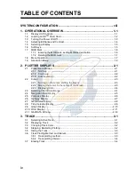
Page 6: ...2 2 2 Cursor 2 3 2 2 1 Turning on the cursor shifting the cursor 2 3 2 2 2 Moving the cursor to the center of the screen 2 3 2 2 3 Displaying data 2 4 2 3 Selecting Chart Scale Range 2 4 2 4 Navigation Data Display 2 5 2 5 Compass Display 2 6 2 6 Highway Display 2 7 2 7 GPS Status Display 2 8 2 8 Tide Celestial Display 2 9 2 9 Graph Display 2 10 2 10 Wind Display 2 11 2 11 NAVDATA Window 2 12 3 TR...

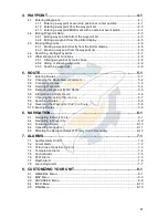
Page 7: ... Entering Routes 5 1 5 2 Changing the Route Name Comment 5 2 5 3 Connecting Routes 5 3 5 4 Inserting Waypoints 5 4 5 5 Removing Waypoints from a Route 5 5 5 6 Information on Route Report 5 6 5 7 Changing the Color of Route Line 5 7 5 8 Searching Routes 5 8 5 9 Reversing the Waypoints Order in a Route 5 8 5 10 Erasing Routes 5 8 6 NAVIGATION 6 1 6 1 Navigating to Quick Points 6 1 6 2 Navigating to ...

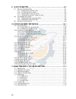
Page 8: ...manual mode 10 10 10 3 2 Selecting display range 10 10 10 3 3 Adjusting the gain 10 11 10 4 Measuring Depth Time 10 12 10 5 Reducing Interference 10 13 10 6 Reducing Low Level Noise 10 14 10 7 Erasing Weak Echoes 10 15 10 8 White Marker 10 16 10 9 Picture Advance Speed 10 17 10 10Alarms 10 18 10 10 1 Audio alarm On Off 10 18 10 10 2 Fish alarm 10 19 10 10 3 Fish alarm B L 10 19 10 11Water Temperat...

Page 9: ...Chart AP 6 SPECIFICATIONS SP 1 INDEX IN 1 Notice for SD Card We confirmed that the following brands of SDTM cards can be used for uploading down loading data For SDTM cards other than listed below we have not yet confirmed if they are compatible with GP 7000 F Kingstone Viking EP Memory SANDISK Panasonic Toshiba PQI Power Quotient ADTEC buffalo I O DATA Hagiwara Sys com LEXAR www reelschematic com...

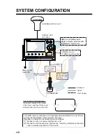
Page 10: ...LAY UNIT GP 7000F How to remove the hard cover Place your thumbs at the center of the cover and then lift the cover while pressing it with your thumbs This GPS receiver complies with Canadian standard RSS 210 Low Power License Exempt Radio communication Devices Operation is subject to the following two conditions 1 this device may not cause interference and 2 this device must accept any interferen...

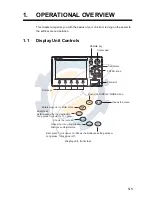
Page 11: ...keys Card slot Cursor pad RANGE key ENTER knob See below MENU DISP MOB WPT TLL GOTO ROUTE CLEAR POWER BRILL Opens the menu Opens the DISPLAY MODE menu Enters waypoint or MOB mark Brief press Sets releases the the destination Long press Outputs the TLL data Closes the menu and window Silences audible alarms Brief press Turns power on Shows the brilliance setting window Long press Turns power off Sh...

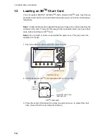
Page 12: ... desk before handling an SDTM card Note 2 Do not insert or remove a card while the power is on This may cause the equipment to freeze 1 Push down the lid catch to open the card slot cover Card slot cover 2 Insert appropriate SDTM chart card label side up to any slot SDTM chart card 3 Press the center of the lid catch to close the card slot cover to protect the chart drive Keep the slot cover close...

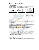
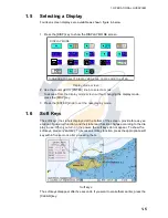
Page 13: ...y after turning the power on When the GPS receiver finds its position NO FIX changes to 2D or 3D to show that position data is now accurate Turning the power off Press and hold the POWER BRILL key until the screen goes blank about four sec onds In about 30 seconds the last used display appears You can go to the last used display faster by pressing any key when this screen appears GP 7000F GPS PLOT...

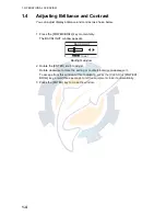
Page 14: ...w appears Backlight window 2 Rotate the ENTER knob to adjust Rotate clockwise to raise the setting or counterclockwise to decrease it To escape from this window without adjusting press the CLEAR or POWER BRILL key or wait three seconds to let the equipment close it automatically 3 Press the ENTER key to close the window BACKLIGHT ENTER TO SET www reelschematic com www reelschematic com ...

Page 15: ...e soft keys their labels displayed at the bottom of the screen provide for easy ex ecution of a desired function and their label and function change according to the dis play in use When you turn on the power the soft keys do not appear To show the soft keys press any soft key To access a soft key function press the appropriate soft key within five seconds after accessing them Soft keys The soft k...

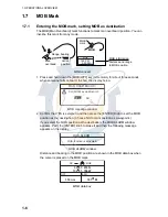
Page 16: ...nation Choose NO to mark position as a waypoint If you select the MOB position as the destination the MOB ALARM window appears Push the ENTER knob to erase it and then the following message appears on the display MOB ALARM window Distance and bearing to the MOB position are shown in the MOB data box when the cursor is placed on the MOB mark MOB data box Man overboad Range bearing Current position ...

Page 17: ...cted by rotating the ENTER knob or operating the cursor pad However this manual describes operating proce dure using the ENTER knob Using the ENTER knob 1 Press the MENU key to show the menu bar Menu bar 2 Rotate the ENTER knob to choose a menu title and then push the ENTER knob to show the menu For example choose GENERAL to display the GENERAL menu General menu 3 Rotate the ENTER knob to choose a...

Page 18: ...e GENERAL to display the GENERAL menu General menu 3 Press T to choose an item and then press X to show its option window For example choose LANGUAGE 4 Press T to choose an option and then press X to close the window To cancel press W 5 To close all menus and option windows press the MENU key To close option windows one by one press the CLEAR key Menu Bar GENERAL PLOTTER MAP ALARMS ADVANCED INFO F...

Page 19: ...d then push the ENTER knob 6 Rotate the ENTER knob to choose COURSE and then push the ENTER knob 7 Enter the course Setting range 0 to 359 by rotating the ENTER knob pressing the W or X and then press the SAVE soft key Note You can return the value to zero by pressing the CLR FLD soft key 8 Enter SPEED DATE and TIME 9 Rotate the ENTER knob to choose CURSOR CONTROL and then push the ENTER knob 10 R...

Page 20: ...plotter display 2 Rotate the ENTER knob to choose ADVANCE and then push the ENTER knob 3 Rotate the ENTER knob to choose ECHO SOUNDER SIMULATION and then push the ENTER knob 4 Rotate the ENTER knob to choose On and then push the ENTER knob 5 Press the MENU key to close the menu 6 Choose the sounder display on the display mode screen www reelschematic com www reelschematic com ...

Page 21: ...oft key to show the soft key labels 2 Press the NORTH UP soft key to show the north up display North zero degree is at the top of the display When the cursor is on the own ship moves and the chart is fixed True motion When the cursor is off the chart waypoints and other marks move and own ship is fixed Relative motion To turn the cursor off press the CENTER soft key Plotter display north up mode 0...

Page 22: ... 2 1 3 Auto course up Press the AUTO CSE UP soft key to show the automatic course up display The course or heading is at the top of screen at the moment the auto course up mode is selected When own ship is off its intended course by 30 default setting this degree can be changed on NAVIGATION menu For details see chapter 8 or more it is au tomatically brought back to perpendicular Plotter display a...

Page 23: ...ta is shown in the NAVDATA window This window can be enabled or disabled by pressing the NAVDATA ON soft key NAVDATA window Also when the cursor is placed on own ship s position its data is shown as follows Own ship s position data window 2 2 2 Moving the cursor to the center of the screen Press the CENTER soft key to return the cursor to the screen center 25 04 933E 077 21 051W COG 007 M SOG 0 10...

Page 24: ...ow ex wreck 3 If you want to know more details press the Details soft key Object detail window ex wreck 4 Rotate the ENTER knob to choose the item you want to know more about Detailed information appears in the lower column 5 Press the CLEAR key to close the window 2 3 Selecting Chart Scale Range Chart scale range may be selected with the RANGE key The RANGE key zooms in the chart RANGE key zooms ...

Page 25: ...e selection window as shown below 4 Rotate the ENTER knob to choose the data to show and then press it The item window ex units appears 5 Rotate ENTER knob to select the unit The data selected at step 2 changes to your selection 6 Press the CLEAR key to erase the reverse video LATITUDE 22º03 730N LONGITUDE 137º57 870E SOG 12 0KTS COG 7º M TRIP 111 5 nm TEMP 10 3ºF TIME 12 28 AM DATE Apr 17 04 DEPT...

Page 26: ...o return to in tended course It is shown in red when you should steer left and green when you should steer right In the example above you would steer left to return to course To maintain course steer the vessel so the own ship marker stays at the center of the XTE monitor Note that the XTE range can be changed by rotating the ENTER knob Nav data Data marked with in above can be changed to display ...

Page 27: ... course Highway display Changing the scale You can change the scale of the highway display to 0 2 0 5 1 0 2 0 4 0 or 10 0 nm Rotate the ENTER knob to change it Note that the available range depends on own ship s position Nav data Data marked with in above can be changed to display See page 2 5 TIME 12 28AM SOG 12 0KTs COG 044º Turn knob to change scale 0 2nm Course Speed Current time Own ship mark...

Page 28: ...IRING LONGITUDE LATITUDE HDOP SOG Kts DATE TIME 131 48 608W 12 5 07 14 25 31 01 11 20 28 07 01 11 14 25 31 28 Position DOP value Receive signal level Bars show satellite signal level Satellites in brown are used in fixing position Estimated position in the sky and satellite number in brown circle is used for positioning www reelschematic com www reelschematic com ...

Page 29: ...d to move the cursor and then rotate the ENTER knob to choose the date When you want to clear all values press the CLR FLD soft key To escape press the CANCEL soft key 3 Press the SAVE soft key to set ENTER to change Date Turn the KNOB to set DLS STANDARD time Nearest Tide Station High Water Low Water From tide Sunrise Sunset Moonrise Moonset Date Time nm 03 50 PM U 01 49 AM U 10 29 AM U 10 07 PM ...

Page 30: ...graphs Sequence of graph display Depth Graph Page 1 of 4 40 2 30 2 20 2 10 2 03 33 03 34 03 35 Depth graph Wind Graph Page 2 of 4 1 2 2 2 3 2 4 2 03 33 03 34 03 35 Wind graph Water Temp Graph Page 3 of 4 66 2 67 2 68 2 69 2 03 33 03 34 03 35 Water temperature graph SOG Graph Page 4 of 4 0 5 0 7 1 0 1 2 03 33 03 34 03 35 SOG graph 1 0 kts 9 6 Ft 3 1 knot 67 4 F GRAPH TYPE soft key GRAPH TYPE soft k...

Page 31: ...3 Rotate the ENTER knob to choose WIND GRAPH and then push the ENTER knob 4 Rotate the ENTER knob to select True or Apparent as appropriate True The Speed and direction relative to due north Apparent The direction in relation to ship s bow and speed of the wind as it appears to those on board relative to the speed and direction of the boat combi nation of the true wind and the wind caused by the b...

Page 32: ...ob to choose data and then press it 5 Depending on the data selected a unit window may appear In this case rotate the ENTER knob to choose the desired unit and then press it 6 Press the CLEAR key to erase the reverse video Resetting the trip data 1 Press the NAV DATA soft key to show the NAVDATA window if it is not already shown 2 Press the CLEAR key to hide soft keys 3 Press and hold the MENU key...

Page 33: ...ate or course Note that other track related settings are available for the track chosen here 1 Press the MENU key to show the menu bar Menu bar 2 Rotate the ENTER knob to choose PLOTTER from the menu bar 3 Push the ENTER knob to show the PLOTTER menu Plotter menu 4 Rotate the ENTER knob to choose TRACK and then push the ENTER knob Track menu Menu Bar GENERAL PLOTTER MAP ALARMS ADVANCED INFO FIND T...

Page 34: ...Press the MENU key to close the menu 3 3 Changing Track Color Track can be displayed in black default setting light green red pink yellow gray brown and dark green It can be useful to change track color on a regular basis to dis criminate the active tracks 1 Choose TRACK from the PLOTTER menu and then push the ENTER knob 2 Choose LINE COLOR and then push the ENTER knob 3 Rotate the ENTER knob to c...

Page 35: ...al GPS navi gator is stored into the unit s memory at an interval of time or distance A shorter inter val provides for better reconstruction of the track but the storage time of the track is reduced When the track memory becomes full the oldest track is erased to make room for the latest 3 6 1 Track plotting method Track may be plotted by time or distance 1 Choose TRACK from the PLOTTER menu 2 Cho...

Page 36: ... This section shows you how to erase the active track 1 Choose TRACK from the PLOTTER menu 2 Choose DELETE and then push the ENTER knob Delete window 3 Push the ENTER knob to erase the track To cancel rotate the ENTER knob to choose NO and then push the ENTER knob 4 Press the MENU key 0 01 0 05 0 1 0 5 1 0 2 0 5 0 10 0 1sec 5 sec 10 sec 30 sec 1 min 5 min 10 min 30 min 1 h Distance window Time win...

Page 37: ...off to enter a waypoint at own ship position or turn it on to enter a way point at cursor position A newly entered waypoint is saved to the waypoint list under the youngest empty way point number 1 Press the MOB WPT key momentarily to store your position as a waypoint When the cursor is displayed the waypoint is entered at the cursor position The new waypoint window appears and it shows waypoint n...

Page 38: ... and ENTER knob to enter longitude data and then press the SAVE soft key 11 Rotate the ENTER knob to choose SHAPE in the SHAPE COLOR section 12 Push the ENTER knob to show the waypoint mark shape selection window Waypoint mark shape selection window 13 Rotate the ENTER knob to choose shape desired 14 Push the ENTER knob 15 Rotate the ENTER knob to choose COLOR and then push the ENTER knob Waypoint...

Page 39: ... When cursor is turned on it is entered at the cursor position 5 If desired change waypoint data choose EDIT at the bottom of screen and fol low the paragraph 4 2 6 Press the CLEAR key to close the WAYPOINT LIST Note 1 The WAYPOINT LIST can also be shown by pressing the WPT QWP LST soft key which is shown when the cursor is placed on a waypoint Note 2 You can change the page of the WAYPOINT LIST b...

Page 40: ... switch is connected 1 Press the MENU key to show the menu bar 2 Rotate the ENTER knob to choose ADVANCED from the menu bar and then push the ENTER knob 3 Rotate the ENTER knob to choose INPUT OUTPUT and then push the ENTER knob 4 Rotate the ENTER knob to choose EXTERNAL EVENT and then push the ENTER knob 5 Choose Off WPT or MOB as appropriate and then push the ENTER knob 6 Press the MENU key to c...

Page 41: ...b 9 Press the CLEAR key to close the list 4 2 2 Editing a waypoint from the plotter display You may edit waypoints from the plotter display two ways from the waypoint window or directly on the plotter display From waypoint window 1 Operate the cursor pad to place the cursor on the waypoint you want to edit 2 Press the EDIT soft key to show the waypoint window Waypoint window 3 Edit data as appropr...

Page 42: ...hoose PLOTTER followed by WAYPOINTS and then push the ENTER knob to show the WAYPOINT LIST 3 Press the cursor pad S T to choose the waypoint you want to delete 4 Rotate the ENTER knob to choose DELETE at the bottom of the screen and then push the ENTER knob 5 Rotate the ENTER knob to select DELETE SELECTED and then push the ENTER knob If you want to delete all waypoints in the list choose DELETE A...

Page 43: ...ts 1 Open the WAYPOINT LIST 2 Rotate the ENTER knob to choose SORT at the bottom of the screen 3 Push the ENTER knob to show the item window Sort window 4 Rotate the ENTER knob to choose a sorting method A Z ASCENDING Sorting waypoints in ascending alphanumeric order Z A DESCENDING Sorting waypoint in descending alphanumeric order DISTANCE ASC Sorting waypoints in order of increasing distance to o...

Page 44: ...bottom of screen 3 Push the ENTER knob to show the ICON window 4 Rotate the ENTER knob to choose SELECT and then push the ENTER knob The waypoint mark shape selection window appears Waypoint mark shape selection window Note ALL shows all waypoints 5 Rotate the ENTER knob to choose the mark shape which you want to search and then push the ENTER knob The list shows waypoints with the chosen mark sha...

Page 45: ...nly the mark of the waypoint selected at step 2 HIDE Hides the name and mark of the waypoint selected at step 2 SHOW ALL Shows the names and marks of all waypoints ICON ALL Shows only marks of all waypoints HIDE ALL Hides the names and marks of all waypoints 5 Push the ENTER knob 6 Press the CLEAR key to close the menu 4 5 3 Searching waypoints You can search for waypoint by name as follows 1 Open...

Page 46: ...4 WAYPOINT 4 10 This page is intentionally left blank www reelschematic com www reelschematic com ...

Page 47: ...nob to show the route list Note The route list can also be shown by placing the cursor on a waypoint and then pressing the ROUTE LIST soft key Route list 4 Rotate the ENTER knob to choose NEW at the bottom of screen and then push the ENTER knob to show the new route menu The new route is automatically named with the youngest empty route number and current date is used as the comment Name and comme...

Page 48: ...r pad S T to choose the route you want to edit 3 Rotate the ENTER knob to choose RENAME at the bottom of screen and then push the ENTER knob To change comments choose COMMENT and then push the ENTER knob 4 Edit the route name as appropriate Press the cursor pad to move the digit cursor 5 Press the SAVE soft key 6 Press the CLEAR key to close the list CANCEL COORD TYPE SAVE 1 34 41 895 N 135 21 109...

Page 49: ... the second route and then push the ENTER knob 7 Press the SAVE soft key 8 Press the CLEAR key twice to close the menu Note The maximum number of waypoints in a route is 35 If this number is exceeded an error message appears In this case delete waypoints in one or both routes so the total number of waypoints does not exceed 35 CONNECT ROUTE CANCEL FORW RVRS SEARCH NAME SAVE LENGTH 3 07 nm WAYPOINT...

Page 50: ...point by the SORT or SEARCH function 6 Push the ENTER knob to enter the waypoint 7 Press the SAVE soft key to close the route menu 8 Press the CLEAR key to close the route list CANCEL COORD TYPE SAVE 1 34 41 895 N 135 21 109 W 34 43 776 N 135 17 883 W 34 46 007 N 135 19 521 W 34 80 398 N 135 35 354 W 34 28 361 N 135 49 239 W 34 24 242 N 135 46 753 W LEG ROUTE NAME 0001RT______ COMMENT 17 33_ JUL10...

Page 51: ... the route list 1 Show the route list 2 Press the cursor pad S T to choose a route 3 Rotate the ENTER knob to select EDIT at the bottom of screen and then push the ENTER knob to show the route menu 4 Press the cursor pad S T to choose the waypoint you want to remove 5 Press the DELETE soft key 6 Press the SAVE soft key 7 Press the CLEAR key to close the list Removing a waypoint from the plotter di...

Page 52: ... NAME COLOR INVERT CLEAR SPEED FUEL ROUTE REPORT Route 1 NAME 0001RT SPEED 10 0 Kts FUEL 10 0 h WAYPOINT LATITUDE LONGITUDE BRG nm LDST nm TDST M TIME FUEL 0001WP 0002WP 0003WP 34 01 583N 124 53 634W 33 59 455N 124 57 228W 33 59 455N 124 48 527W 220 075 3 661 7 214 3 661 10 88 000 21 001 15 3 6 10 8 Waypoint name Waypoint position Bearing Leg distance Total distance Estimated navigation time betwe...

Page 53: ... knob to choose FUEL at the bottom of screen and then push the ENTER knob to show the FUEL window 3 Enter the fuel consumption of your boat You can change the digit by pressing the cursor pad W X 4 Press the SAVE soft key 5 7 Changing the Color of Route Line You can select the color for the route line among 8 colors black light green red pink yellow gray brown and dark green 1 Open the route list ...

Page 54: ... ENTER knob to choose PLOT at the bottom of screen 4 Push the ENTER knob The plotter display appears with the chosen route at the screen center 5 9 Reversing the Waypoints Order in a Route The order of waypoints in a route can be reversed as follows 1 Open the route list 2 Press the cursor pad S T to choose the route desired 3 Rotate the ENTER knob to choose REVERSE at the bottom of the screen 4 P...

Page 55: ... knob to choose CURSOR and then push the ENTER knob A line connects between own ship and destination marked DEST and it shows the shortest course to the destination The destination is marked with a flag Also range and bearing from own ship to the destination appear in the data win dow This location is saved to the WAYPOINT LIST as waypoint DEST Quick point data window You can also set the quick po...

Page 56: ...ote You can continue to add the quick point up to 35 points If you want to create a new quick route place the cursor on a leg in the route and then press the RELEASE soft key Creating a quick pattern route SAR function The SAR Search and Rescue function automatically creates and saves routes in one of three set patterns The three patterns are EXPANDING SQUARE CREEPING LINE AHEAD and CIRCULAR To cr...

Page 57: ...tting window 3 Rotate the ENTER knob to choose the bearing of the second waypoint from the first waypoint and then press the SAVE soft key Setting range 0 to 359 North is 0 axis The cursor moves to the first digit of SPACE automatically 4 Rotate the ENTER knob to set the range between the first waypoint and the sec ond waypoint and then press the SAVE soft key Setting range 1 to 999 9 nm The curso...

Page 58: ... ahead route do the following 1 Press the ROUTE key followed by SAR PATTERN soft key to show the pattern window 2 Rotate the ENTER knob to choose CREEPING LINE AHEAD and then push the ENTER knob to show the CREEPING LINE AHEAD setting window The cursor chooses the first digit of DIRECTION automatically CREEPING LINE AHEAD setting window 3 Rotate the ENTER knob to set the bearing which the route fo...

Page 59: ...AVE key Setting range 0 to 999 9 nm The cursor moves to the WPTs setting automatically 6 Rotate the ENTER knob to choose the number of waypoints at WPTs and then press the SAVE soft key Setting range 1 to 35 points The cursor moves to the ROTATION setting automatically 7 Rotate the ENTER knob to choose the direction which the route is to follow L left R right 8 Press the SAVE soft key to store the...

Page 60: ...e first digit of DIRECTION automatically CIRCULAR setting window 3 Rotate the ENTER knob to set the bearing of the first waypoint and then push the ENTER knob Setting range 0 to 359 North is 0 axis The cursor moves to the first digit of SECTOR automatically 4 Rotate the ENTER knob to set the angle of an isosceles triangle formed by three waypoints and then push the ENTER knob Setting range 0 to 35...

Page 61: ...setting automatically 6 Rotate the ENTER knob to choose L or R and then push the ENTER knob L The first turn is made in left direction R The first turn is made in right direction 7 Press the SAVE soft key to store the route in the list 001QW 002QW 003QW Degree set at SECTOR 001QW 002QW 003QW Range set at LENGTH the radius of the route 001QP 002QP 003QP 004QP 005QP 006QP 001QP 002QP 003QP 004QP 005...

Page 62: ...ith the ENTER knob and then push the ENTER knob Then the display shows the location of those services The appropriate port names are shown in order of distance from own ship Rotate the ENTER knob to choose the port desired and push the ENTER knob twice The service marks of the selected port appear If you are okay to set this port as destination press the ENTER knob to close the window Confirm that...

Page 63: ...place the cursor at a location not occupied by waypoint 2 Press the TLL GOTO key to show the GOTO window GOTO window 3 Rotate the ENTER knob to choose WAYPOINT and then push the ENTER knob The SELECT NAME window appears SELECT NAME window for waypoints 4 Enter the waypoint name you want to set as destination 5 Press the SAVE soft key Selecting waypoint through WAYPOINT LIST 1 Press the MENU key to...

Page 64: ...navigation from any waypoint in a route 1 Open the route list 2 Press the cursor pad S T to choose the route desired 3 Rotate the ENTER knob to choose PLOT at the bottom of the screen and then push the ENTER knob The plotter display appears 4 Press the cursor pad to place the cursor on any waypoint which is part of the route you want to set as destination 5 Press the TLL GOTO key A line runs betwe...

Page 65: ...hoose EDIT at the bottom of screen and then push the ENTER knob The route menu appears 5 Press the cursor pad S T to choose the waypoint you want to skip 6 Press the SKIP soft key 7 Press the SAVE soft key to close the route menu 8 Press the CLEAR key to close the route list 6 4 Cancelling Navigation 1 Press the TLL GOTO key The confirmation window appears 2 Confirm that STOP is selected and then ...

Page 66: ...the ENTER knob to choose INPUT OUTPUT and then push the ENTER knob 4 Rotate the ENTER knob to choose C LINK and then push the ENTER knob 5 Choose Secondary Station Primary Station or Off as appropriate and then push the ENTER knob Secondary Station This unit is designated as the secondary plotter Destination cannot be set or changed from the secondary plotter Primary Station This unit is designate...

Page 67: ...he reason for the alarm has disappeared You may set up the alarms on the ALARM menu 1 Press the MENU key to show the menu bar Menu bar 2 Rotate the ENTER knob to choose ALARMS and then push the ENTER knob to show the ALARMS menu Alarms menu Menu Bar GENERAL PLOTTER MAP ALARMS ADVANCED INFO FIND AUDIBLE ALARM Off ARRIVAL ALARM Off XTE ALARM Off TEMPERATURE ALARM Off DEPTH ALARM Off ANCHOR ALARM Off...

Page 68: ...r boat is approaching a destination waypoint The area that defines an arrival zone is that of an imaginary circle which you approach from the outside of it The alarm will be released if your boat enters the imaginary cir cle Note that this alarm is available only when a destination is set How the arrival alarm works 1 Open the ALARMS menu 2 Rotate the ENTER knob to choose ARRIVAL ALARM and then pu...

Page 69: ...otate the ENTER knob to choose XTE ALARM and then push the ENTER knob 3 Rotate the ENTER knob to choose x xx value nm and then push the ENTER knob 4 Rotate the ENTER knob to enter value To change the digit press the cursor pad W X 5 Press the SAVE soft key and MENU key in order to close the menu Alarm Destination waypoint Own ship position Alarm setting Intended course Off 0 00 nm www reelschemati...

Page 70: ...he cursor is at the top line and then push the ENTER knob 4 Rotate the ENTER knob to choose Within Range or Out of Range as appropriate and then push the ENTER knob 5 Rotate the ENTER knob to choose Max and then push the ENTER knob 6 Enter the value for the maximum temperature and then press the SAVE soft key 7 Rotate the ENTER knob to choose Min and then push the ENTER knob 8 Enter the value for ...

Page 71: ... set 1 Open the ALARMS menu 2 Rotate the ENTER knob to choose STW ALARMS and then push the ENTER knob 3 Confirm that the cursor is located at the top line and then push the ENTER knob 4 Rotate the ENTER knob to choose On and then push the ENTER knob 5 Rotate the ENTER knob to choose Max and then push the ENTER knob 6 Rotate the ENTER knob to enter the value and then press the SAVE soft key 7 Rotat...

Page 72: ... ENTER knob 4 Rotate the ENTER knob to choose On and then push the ENTER knob 5 Rotate the ENTER knob to choose Depth and then push the ENTER knob 6 Enter the starting point of range and then press the SAVE soft key 7 Rotate the ENTER knob to choose Range and then push the ENTER knob 8 Enter the alarm range and then press the SAVE soft key 9 Press the MENU key to close the menu Off Depth 0000 0 Ft...

Page 73: ... Enter the depth value desired 5 Press the SAVE soft key 6 Press the CLEAR key 7 Rotate the ENTER knob to choose GROUNDING ALARM RANGE and then push the ENTER knob 8 Rotate the ENTER knob to choose the range and then push the ENTER knob 9 Push the MENU key in order to close the menu A triangle appears next to own ship mark to show the alarm range When the grounding alarm warns you can know what ki...

Page 74: ...7 ALARMS 7 8 This page is intentionally left blank www reelschematic com www reelschematic com ...

Page 75: ... Night Normal and NOAA NOAA like colors TIME LINE Choose the interval for the time line own ship s vector from among 2 min 10 min 30 min 1 hour 2 hours and Infinite The length of the bar shows distance your ship will move within selected time Also the line can be erased by selecting Off TIME REFERENCE GPS uses UTC time If you would rather use local time key in the time difference be tween it and U...

Page 76: ... when own ship reaches an edge of screen This function is useful to overlook the forward without manual cursor operation Choose On to enable the SHIP OFFSET Note that this func tion is not available when the cursor is turned on WIND GRAPH See section 2 10 for details about the wind display UNITS OF MEASURE Chooses unit of measurement for distance speed depth altitude and temperature Distance nm sm...

Page 77: ...ed and own ship position or cur sor position as reference coarse chart data area of low accuracy is shown in white when this setting is disabled When enabled coarse chart data is shown in the same scale as detailed chart data and its location is marked with a dots SAFETY STATUS BAR When this item is turned On the following menu bar appears at the top of screen NORMAL or U ZOOM or O ZOOM This indic...

Page 78: ...wn in red when the GROUNDING alarm detects the low risk object when the GROUNDING alarm is turned on NAV AIDS PRESENTATION Chooses what kind of navaids symbols to display International or US CURRENTS PREDICTION Displays the current prediction window which shows the direction and speed of the current at the place of current symbol arrow shaped selected with cursor Current prediction window This win...

Page 79: ...S On Off Off Off NAV AIDS LIGHT SECTOR On No Sector No Sector Off ATTENTION AREAS On On Off Off TIDES CURRENTS On Off Off On SEABED TYPE On Off Off Off PORTS SERVICES On On Off Off TRACK ROUTES On Off Off Off UNDERWATER OBJECTS SETTINGS UNDERWATER OBJECTS LIMT 1000 ft 33 ft 166 fa 5 fa 304 m 10 m 184 pb 6 pb ROCKS Icon Depth Icon Icon Icon OBSTRUCTIONS Icon Depth Icon Icon Icon DIFFUSERS Icon Dept...

Page 80: ... Auto Off Off VALUE ADDED DATA On Off Off Off CHART LOCK On On On On Menu Item Settings MARINE SETTINGS NAMES On Off NAME TAGS On Off NAV AIDS LIGHT SECTORS On Off No Sector ATTENTION AREAS On Off TIDES CURRENTS On Off SEABED TYPE On Off PORTS SERVICES On Off TRACKS ROUTES On Off UNDERWATER OBJECTS SETTINGS UNDERWATER OBJECTS LIMIT 0 1000 ft 0 166 fa 0 304 m 0 184 pb ROCKS Off Icon Icon Depth OBST...

Page 81: ...3 06 pb DEPTH RANGE MAX 16 33 66 ft 03 06 11 fa 05 10 20 m 03 06 12pb LAND SETTINGS LAND ELEVATIONS On Off LAND ELEVATION VALUES On Off ROADS On Off POINTS OF INTEREST On Off CHART SETTINGS LAT LON GRID On Off CHART BOUNDARIES On Off Auto VALUE ADDED DATA On Off CHART LOCK On Off www reelschematic com www reelschematic com ...

Page 82: ...ng the raw GPS fixes You can choose the setting from among Off Low Medium and High The higher the setting the more smoothed the raw data however too high a setting slows response time to change in latitude and lon gitude This is especially noticeable at high ship s speeds Off is normal setting increase the setting if the GPS fix changes SPEED FILTER During position fixing ship s velocity speed is ...

Page 83: ...urse up mode Setting range 5 to 60 Item Settings BEARINGS Choose how to calculate bearing Mag or True True bearing is a bearing measured using true North as the reference direction and it is calculated by the formula True Bearing Magnetic Bearing Magnetic Variation Magnetic bearings are measured with magnetic north as the reference direction Select Mag when using a mag netic compass True when usin...

Page 84: ...ursor Choose a location and then open the INFO menu and select item 8 5 FIND Menu You can find objects on the chart data in use dividing with the category of TIDE STA TION WRECKS and OBSTRUCTIONS Choose the appropriate category from the FIND menu and then push the ENTER knob www reelschematic com www reelschematic com ...

Page 85: ...h the ENTER knob Plotter menu 3 Rotate the ENTER knob to choose MEMORY CARD and then push the ENTER knob The MEMORY CARD list appears Memory card list 4 Rotate the ENTER knob to choose CHANGE at the bottom of screen and then push the ENTER knob to change the active slot The currently selected slot is shown at the left hand top corner SLOT 1 Upper slot SLOT 2 Lower slot TRACK ROUTES WAYPOINTS MEMOR...

Page 86: ... 3 Rotate the ENTER knob to choose PLOTTER and then push the ENTER knob to show the PLOTTER menu 4 Rotate the ENTER knob to choose MEMORY CARD and then push the ENTER knob to show the MEMORY CARD list 5 Rotate the ENTER knob to choose SAVE and then push the ENTER knob 6 Press the ENTER knob and then enter the file name for which you want to save the data under 7 Press the SAVE soft key 8 Rotate th...

Page 87: ... 1 Sending receiving waypoints data You may send receive all waypoints data as follows When sending data set the con nected equipment for receiving 1 Connect the PC or another GP 7000 F to the equipment 2 Choose INPUT OUTPUT from the ADVANCED menu 3 When sending data follow steps shown below 1 Choose NMEA 1 OUTPUT NMEA 2 OUTPUT or RS232 3 OUTPUT appropri ately The sentence window appears Sentences...

Page 88: ...CEIVE at the bottom of the screen SEND Sending all waypoints in the internal memory to external equipment RECEIVE Receiving all waypoints to the internal memory from external equip ment 8 Press the ENTER knob to execute When the sending is completed the message User Points sending appears 9 For receiving do the operation for sending on the PC or GP 7000 F When the receiving is completed the messag...

Page 89: ... sentence window appears Sentences window 2 Choose WPL and RTE sentences and then set these on 4 When receiving data follow steps shown below 1 Choose NMEA 1 INPUT NMEA 2 INPUT or RS232 3 INPUT appropriately and then push the ENTER knob 2 Communication format between this unit and PC or GP 7000 F should be the same 5 Press the CLEAR key several times to close the window and menus 6 Open the ROUTE ...

Page 90: ...ort or PC NMEA IN port 1 Press the MENU key to show the menu bar 2 Rotate the ENTER knob to choose ADVANCED from the menu bar and then push the ENTER knob 3 Rotate the ENTER knob to choose INPUT OUTPUT and then push the ENTER knob 4 Rotate the ENTER knob to choose WPL RTE FORMAT and then push the ENTER knob 5 Choose Furuno or Standard as appropriate and then push the ENTER knob Standard NMEA forma...

Page 91: ...termined The entire process begins in the sounder Transmitter power is sent to the transducer as a short pulse of electrical energy The electrical signal produced by the transmitter is converted into an ultrasonic signal by the transducer and transmitted into the water Any returning signals from intervening objects such as a fish school are received by the transducer and converted into an electric...

Page 92: ...e ful for general detection and judging bottom condition 200 kHz picture The higher the frequency of the ultrasonic pulse the better the resolution Therefore the high frequency is ideal for detailed observation of fish school Sounding area and transmission frequency Color bar Depth scale Tx frequency Depth 50 30 Temp scale Water temp graph 50 0 Minute marker Bottom echo Zero line Fish echo 40 0 50...

Page 93: ...picture To select transmission frequency do one of the following Using the soft key Press the 50 200 kHz soft key to choose the frequency Through the menu 1 Press the MENU key to show the menu bar Menu bar 2 Rotate the ENTER knob to choose SOUNDER and then push the ENTER knob to show the SOUNDER menu DISPLAY MODE TURN KNOB TO SELECT DISPLAY MODE AND PRESS KNOB TO ENTER Menu Bar GENERAL SOUNDER SEN...

Page 94: ... discrimination and A scope Dual frequency The dual frequency display provides both 50 kHz and 200 kHz pictures This display is useful for comparing the same picture with two different sounding frequencies Dual frequency display To show the dual frequency display do the following 1 Press the DISP key 2 Rotate the ENTER knob to choose icon 3 Push the ENTER knob AUTO MODE PRESET MANUAL DISPLAY MODE ...

Page 95: ...choose SOUNDER and then push the ENTER knob Sounder menu 3 Rotate the ENTER knob to choose DISPLAY MODE and then push the ENTER knob Display mode window 4 Rotate the ENTER knob to choose the mode desired and then push the ENTER knob 5 Press the MENU key to close the menu NORMAL BOTTOM LOCK BOTTOM ZOOM MARKER ZOOM BOTTOM DISCRIMINATION AUTO MODE PRESET MANUAL DISPLAY MODE NORMAL FREQUENCY 50 KHz PI...

Page 96: ... bottom zoom display expands bottom and bottom fish echoes by the chosen zoom range and is useful for determining bottom hardness A bottom displayed with a short echo tail usually means it is a soft sandy bottom A long echo tail means a hard bottom Note The range of the bottom zoom can be changed at ZOOM RANGE on RANGES menu Bottom zoom display plus normal sounder display 50k 88 7 0 Single frequen...

Page 97: ...ay plus normal sounder display Bottom discrimination display The bottom discrimination mode displays the bottom echo to help you determine bot tom hardness A bottom displayed with a short echo tail usually means it is a soft sandy bottom A long echo tail means a hard bottom Note The range of the bottom discrimination can be changed at BOTTOM LOCK RANGE on RANGES menu Bottom discrimination display ...

Page 98: ...ction automatically selects the proper gain range scale and clutter suppression level according to the depth It works as follows The range changes automatically to locate the bottom on the lower half of the screen The range jumps to one step shallower range when the bottom echoes reach a half way point of the full scale from the top and to one step deeper range when they come to the lower edge of ...

Page 99: ...y 1 Press the AUTO soft key to show the AUTO window Auto window 2 Rotate the ENTER knob to choose FISH or CRUISE as appropriate and then push the ENTER knob Through the menu 1 Press the MENU key to show the menu bar 2 Rotate the ENTER knob to choose SOUNDER and then push the ENTER knob to show the SOUNDER menu 3 Rotate the ENTER knob to choose AUTO MODE PRESET and then push the ENTER knob The AUTO...

Page 100: ... SOUNDER menu 2 Rotate the ENTER knob to choose AUTO MODE PRESET and then push the ENTER knob 3 Rotate the ENTER knob to choose MANUAL and then push the ENTER knob 4 Press the MENU key to close the menu 10 3 2 Selecting display range Press the RANGE or RANGE key to select a range The default ranges in feet are as below Note that the range cannot be changed in the automatic sounder mode You can cha...

Page 101: ...accessed with the SENSITIVITY menu Sensitivity window 2 For menu operation choose GAIN 50 kHz or GAIN 200 kHz as appropriate and then push the ENTER knob 3 Rotate the ENTER knob to adjust Setting range 0 to 100 4 Push the ENTER knob to set 5 Press the MENU key to close the menu Note Gain cannot be adjusted in the automatic sounder mode Gain too high Gain proper Gain too low GAIN 50 000 NOISE LIMIT...

Page 102: ...ard clockwise to shift it downward You may also use the cursor pad S T to shift the VRM 2 Press the cursor pad W X to adjust the time marker to measure time How to measure depth and time VRM white 40 0 Depth to VRM Time marker 50k 97 50 100 0 0 33 Time for a scan line to travel from the right edge of the display to the cross hair cursor ft www reelschematic com www reelschematic com ...

Page 103: ...push the ENTER knob to show the noise limiter window Noise limiter window 3 Rotate the ENTER knob to choose the degree of suppression desired LOW MEDIUM HIGH or turn the noise limiter off 4 Push the ENTER knob and MENU key in order to close the menu Turn the noise limiter circuit off when no interference exists otherwise weak echoes may be missed Interference from other sounder Electrical interfer...

Page 104: ...wing 1 Push the ENTER knob to show the SENSITIVITY window Sensitivity menu 2 Rotate the ENTER knob to choose CLUTTER and then push the ENTER knob The CLUTTER setting is shown in normal video 3 Rotate the ENTER knob to choose the setting value 4 Push the ENTER knob and MENU key in order to close the menu Note The setting range is 0 7 the higher the value the greater the suppression of low level noi...

Page 105: ...ENTER knob to choose level of erasure or OFF as appropriate The higher the number the stronger the echo that will be erased 4 Push the ENTER knob and MENU key in order to close the menu Note Unlike clutter signal level reduces display colors Therefore if you do not wish to reduce colors use clutter instead Weak echoes GAIN 50 000 NOISE LIMITER HIGH CLUTTER 0 WHITE MARKER OFF SIGNAL LEVEL OFF For m...

Page 106: ... knob 4 Rotate the ENTER knob to choose the color to display in white 16 strongest color 0 weakest color As your rotate the knob the number in the white marker window changes the white marker on the echo strength bar shifts and the chosen echo color is dis played in white Color bar when white marker function is active 5 Push the ENTER knob and MENU key in order to close the menu To turn the white ...

Page 107: ... speed desired The fractions in the window denote the number of scan lines produced per trans mission For example 1 8 means one scan line is produced every eight transmis sions STOP freezes the display and it is convenient for taking a picture of the display 4 Push the ENTER knob and MENU key in order to close the menu Note When using a plotter sounder combination display advancement of the sound ...

Page 108: ...ss the MENU key to show the menu bar 2 Rotate the ENTER knob to choose ALARMS and then push the ENTER knob to show the ALARMS menu 3 Rotate the ENTER knob to choose AUDIBLE ALARM and then push the ENTER knob 4 Rotate the ENTER knob to choose Internal Internal External or Off as appropri ate 5 Push the ENTER knob 6 Press the MENU key to close the menu AUDIBLE ALARM Off ARRIVAL ALARM Off XTE ALARM O...

Page 109: ...ow and stronger echoes trigger the alarm or Low blue and stronger echoes trigger the alarm 4 Push the ENTER knob and MENU key in order to close the menu 10 10 3 Fish alarm B L The bottom line fish alarm sounds when a fish echo is within a predetermined distance from the bottom 1 Open the ALARMS menu 2 Rotate the ENTER knob to choose FISH ALARM B L and then push the ENTER knob twice Fish alarm B L ...

Page 110: ...y bottom zoom and marker zoom displays 1 Open the SOUNDER menu 2 Rotate the ENTER knob to choose SOUNDER SETUP and then push the ENTER knob 3 Rotate the ENTER knob to choose PLAYBACK SOUNDER IMAGE and then push the ENTER knob 4 Rotate the ENTER knob to choose Play or S Down Play Rotate the ENTER knob clockwise to scroll the past picture S Down The entire past picture appears 5 Push the ENTER knob ...

Page 111: ... screen by pressing the NAVDATA ON soft key Sounder display Nav data on Depth 50 30 50 0 200k 40 0 50 100 150 0 30 34 40 209N 135 17 485E COG 316 M SOG 12 0 kt DST nm BRG M TRIP 631 nm TEMP 44 0 F STW 11 4 kt DPTH ft MANUAL 120 Current mode Own ship position L L Navigation data www reelschematic com www reelschematic com ...

Page 112: ...TRANSDUCER Selects the transducer to use 600 W or 1 kW TVG 50 KHz 200 kHz TVG Time Varied Gain compensates for propagation attenuation of the ultrasonic waves It does this by equalizing echo presentation so that fish schools of the same size appear in the same density in both shallow and deep waters In addition it reduc es surface noise Note that if the TVG level is set too high short range echoes...

Page 113: ... manual operation you may adjust the bottom echo level detection circuit for both 50 kHz and 200 kHz to stabilize the indication Note If the BOTTOM LEVEL is set too low fish echoes may be recognized as the sea bottom and the depth indication may be unstable Reversely if the setting is too high the depth indication will not be displayed SMOOTHING Smoothes echoes to present stable display The higher...

Page 114: ... and echo color on the screen The top color reddish brown is the strongest color and the lower colors the weakest The bar can be used as a reference to estimate density of a fish school fish species and hardness of the bottom Color bar LF 49 6 1 1 m 0 0 20 40 60 80 0 0 Surface noise Color bar Bottom Zero line Fish school R BRN RED ORANGE YELLOW GREEN LIGHT BLUE BLUE DEEP BLUE Weak Strong No signal...

Page 115: ...rofile Bottom profile A hard and rough bottom appears with a longer tail because it reflects more of the ul trasonic pulse Because of their stronger return shallow echoes appear wider than deep ones even when all bottom conditions are equal Also a longer bottom tail ap pears on slopes because of the difference in traveling time at both edges of the beam angle In the rugged bottom echoes are reflec...

Page 116: ...om nature Fish schools Fish quantity Fish quantity can be estimated to a certain extent from fish echoes on the screen if fish school size and fish school density are kept in mind Fish school size Usually the size of fish echoes on the screen is proportional to the actual size of the fish school However if two fish echoes appear at different depths with the same size the fish school at shallower d...

Page 117: ...A plankton layer a likely place to find fish is displayed in green or blue dots It usually descends in the day and rises at night Plankton Current rip When two ocean currents meet with different speeds directions and water tempera tures a current rip develops A current rip s on screen appearance is as shown below Current rip Fish echo Less Reddish Sparse echo Reddish Dense echo Difference in signa...

Page 118: ...s is caused by air bubbles which block propagation of the sound wave Generally low frequency ultrasonic waves are interrupted more easily than high ones Aerated water False echo Every time ultrasonic pulse is transmitted some radiation escapes on each side of the beam called side lobes Echoes from side lobes show on the display as false imag es as below Surface noise Ultrasonic wave blocked by aer...

Page 119: ...sired DO NOT use chemical cleaners to clean the display unit they may remove paint and markings Wipe the LCD carefully to prevent scratching using tissue paper and an LCD cleaner To remove dirt or salt deposits use an LCD cleaner wiping slowly with tissue paper so as to dissolve the dirt or salt Change paper frequently so the salt or dirt will not scratch the LCD Transducer Check the transducer fa...

Page 120: ...life of the battery is about three years When the battery volt age is low the battery icon appears on the display When this happens contact your dealer to request replacement of the battery Note If you require data currently displayed save it to a SD memory card before re placing the battery Name Type Code No Fuse FGBO A 3A AC125V 000 549 063 FGBO A 125V 3A PBF 000 155 850 10 Name Type Code No Bat...

Page 121: ... little harder no picture appears press the POWER BRILL key and then rotate the ENTER knob there is no response when a key is pressed turn off and on the power the picture goes off suddenly press the POWER BRILL key to turn the power on Plotter troubleshooting If Then position is not fixed within 90 seconds check that antenna connector is firmly fas tened check number of satellites received on the...

Page 122: ...ra tion marine life or air bubbles may be clinging to transducer face on SOUNDER SETUP menu set TRANS MISSION POWER to High the depth indication is not displayed adjust gain and range to display the bottom echo in reddish brown if you are using the manual operation noise or interference shows on the dis play if no noise appears after turning the engine off the engine interference is suspected Call...

Page 123: ... you hear the beep SYSTEM TEST menu 11 5 1 RAM menu The RAM menu checks memory circuit Results for device checks are shown as OK or NG No Good For any NG request service 1 Rotate the ENTER knob to choose RAM menu on the SYSTEM TEST 2 Push the ENTER knob to show the RAM window RAM window 3 Rotate the ENTER knob to select RAM test and then push the ENTER knob to start the RAM test 4 Confirm that OK ...

Page 124: ...tridge The Cartridge item checks internal chart data or the chart card data in use Checking the internal chart data 1 Rotate the ENTER knob to choose Cartridge on the SYSTEM TEST 2 Push the ENTER knob to show the Cartridge window Cartridge window 3 Rotate the ENTER knob to choose Internal Data Base Test and then push the ENTER knob to start the test 4 Confirm the test result Checking the chart car...

Page 125: ...put from the external equipment connected are shown 11 6 Program No You can confirm the software program No by following procedure 1 At the Rotate the ENTER knob to choose ADVANCED and then push the ENTER knob 2 Rotate the ENTER knob to choose SYSTEM UPDATE and then push the ENTER knob to show the System update menu 3 To escape from the System update menu press the MENU key Change parameters Input...

Page 126: ... CLEAR key 7 Press the POWER BRILL key to turn the power off 11 8 GPS Cold Start Cold start clears the Almanac stored in the memory to receive the latest Almanac from the GPS satellites When the equipment has not been used for a long time over one year execute cold start as shown below to receive the latest Almanac 1 Choose ADVANCED from the menu bar and then push the ENTER knob to show the ADVANC...

Page 127: ... to show the AIS menu AIS menu 4 Rotate the ENTER knob to choose DISPLAY and then push the ENTER knob 5 Rotate the ENTER knob to choose On and then push the ENTER knob 6 Rotate the ENTER knob to choose ACTIVATION RANGE and then push the ENTER knob 7 Rotate the ENTER knob to set the range from own ship and then press the SAVE soft key Setting range 0 1 to 50 0 nm AIS targets within this range will ...

Page 128: ...ymbol Description Activated automatically or manually The dashed line shows ship s COG The solid shows target heading Target selected by use for data display A target is declared a lost target when no data is received for three to five reporting intervals When this occurs the target is marked with the dashed tri angle Heading COG Activated target Target selected for data display Lost target AIS NA...

Page 129: ...LEAR key The flashing of the triangle plot symbol continues until you intentionally terminate tracking by pressing CLEAR key tracking of the target This feature helps alert you to targets which may be on a collision course with own ship Setting CPA and TCPA CPA TCPA alarm range must be set up properly taking into consideration the size tonnage speed turning performance and other characteristics of...

Page 130: ...AIS SETUP from the ADVANCED menu and then push the ENTER knob 2 Rotate the ENTER knob to choose CPA ALARM or TCPA ALARM appropriately and then push the ENTER knob 3 Rotate the ENTER knob to choose On and then push the ENTER knob 4 Press the MENU key to close the menu www reelschematic com www reelschematic com ...

Page 131: ...BOLS NORMAL LARGE PERSPECTIVE VIEW Off On DYNAMIC NAV AIDS Off On MIXING LEVELS Off On SAFETY STATUS BAR Off On Icon NAV AIDS PRESENTATION US International CURRENTS PREDICTION Shows the current prediction window MAP CONFIGURATIONS MAP MENU BAR 1 DEPTH SETTINGS DEPTH RANGE MIN 07 16 33 ft 1 3 6 fa 2 5 10 m 1 3 6 pb 33 ft DEPTH RANGE MAX 16 33 66 ft 3 6 11 fa 5 10 20 m 3 6 12 pb 66 ft DISPLAY MODE F...

Page 132: ...n Off WAAS SEARCH Auto Manual NMEA 1 INPUT NMEA 0183 1200 N81 N NMEA 0183 4800 N81 N NMEA 0183 4800 N82 N NMEA 0183 9600 N81 N NMEA 0183 9600 O81 N C COM AIS 38400 Disabled NMEA 1 OUTPUT GLL VTG BWR DBT DPT MTW VHW WCV APA APB HDG BOD XTE RMA RMB RMC GGA HSC AAM GTD MWV ZDA WPL RTE TLL Out NMEA 2 INPUT NMEA 0183 1200 N81 N NMEA 0183 4800 N81 N NMEA 0183 4800 N82 N NMEA 0183 9600 N81 N NMEA 0183 96...

Page 133: ...ATE PORT SERVICES PORT TIDE STATIONS WRECKS OBSTRUCTIONS PORT BY DISTANCE LAKES INFO LAKE BY NAME POINTS OF INTEREST ROUTES WAYPOINTS COORDINATES Longitude Latitude INFO FIND 2 DISPLAY Off On ACTIVATION RANGE 0 1 to 50 0 5 0 nm CPA ALARM Off On CPA LIMIT 0 5 to 50 0 0 5 nm TCPA ALARM Off On TCPA LIMIT 1 to 30 10 min C MAP WEATHER SERVICE www reelschematic com www reelschematic com ...

Page 134: ... to 100 80 NOISE LIMITER OFF LOW MEDIUM HIGH CLUTTER 0 to 7 4 WHITE MARKER OFF 1 to 16 SIGNAL LEVEL Off SL1 to SL9 SENSITIVITY RANGE 1 7 to 4000 ft 15 ft RANGE 2 7 to 4000 ft 30 ft RANGE 3 7 to 4000 ft 60 ft RANGE 4 7 to 4000 ft 120 ft RANGE 5 7 to 4000 ft 200 ft RANGE 6 7 to 4000 ft 400 ft RANGE 7 7 to 4000 ft 1000 ft RANGE 8 7 to 4000 ft 1500 ft ZOOM RANGE 15 to 400 ft 30 ft BOTTOM LOCK RANGE 15...

Page 135: ...viders are compatible with one another thus providing seamless position fixes to SBAS users The illustration below shows the coverage ar ea Accuracy may be affected when using a GEO satellite not within your current lo cation This manual uses WAAS for these three providers generically Provider Satellite type Longitude Satellite No WAAS Inmarsat 3 F4 142 E 122 Inmarsat 3 F3 POR 178 E 134 Intelsat G...

Page 136: ...AP 6 World Time Chart art www reelschematic com www reelschematic com ...

Page 137: ...on Fixing System All in view 8 state Kalman filter 2 5 Position Accuracy GPS 10 m 95 of the time HDOP 4 WAAS 3 m 95 of the time 2 6 Tracking Velocity 999 kt 2 7 Position fixing Time Warm start 12 s approx Cold start 90 s approx 2 8 Position Update Interval 1 s 3 PLOTTER FUNCTIONS 3 1 Effective Projection Area Depending on chart card in use 3 2 Track Display Plot interval by time 1 sec 5 sec 10 sec...

Page 138: ...DER 5 1 Transmit Frequency 50 and 200 kHz dual frequency 5 2 Transmission 600 Wrms or 1 kWrms 5 3 Display range 5 10 20 40 80 150 300 500 m shift 0 1200 m 15 30 60 120 200 400 1000 1500 ft shift 0 4000 ft 5 4 Extension Mode Marker zoom Bottom zoom Bottom rock Bottom descrimination 5 5 Auto Mode Cruising Fishing selected 5 6 Picture advance 6 steps 6 POWER SUPPLY 6 1 Display Unit 12 24 VDC 1 5 0 8 ...

Page 139: ...SP 3 E4429S00D 8 COATING COLOR 8 1 Antenna Unit N9 5 white 8 2 Display Unit Cover 2 5GY5 1 5 Panel N3 0 www reelschematic com www reelschematic com ...

Page 140: ...www reelschematic com www reelschematic com ...

Page 141: ... Creeping line ahead 6 4 CRUISE 10 9 Current prediction 8 4 Cursor 2 3 D Data playing back 9 3 saving 9 2 Date format 8 2 Diagnostics 11 5 Dim menu 11 6 Display mode 8 5 Dual frequency 10 4 E Event switch 4 4 Expanding square 6 3 F FISH 10 9 Fix 8 8 Fuse 11 2 G Gain 10 11 GPS cold start 11 8 GPS status display 2 8 Graph display 2 10 H Highway display 2 7 I Interference 10 13 K Keypad beep 8 1 L La...

Page 142: ... Single frequency 10 2 Soft keys 1 5 Sounder display 10 2 T Time format 8 2 Time line 8 1 Time reference 8 1 Track 3 1 active 3 1 color 3 2 displaying 3 2 erasing 3 4 hiding 3 3 interval 3 3 method 3 3 U Units of measure 8 2 W WAAS AP 5 Water temperature graph 10 20 Waypoint 4 1 editing 4 5 entering 4 1 erasing 4 6 hiding 4 9 list 4 3 searching 4 7 showing 4 9 sorting 4 7 White marker 10 16 Wind d...

Reviews: