background image

Installation Manual

Multi Function Display

Model

 MFDBB

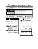
SAFETY INSTRUCTIONS ............................................................................ i

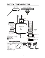
SYSTEM CONFIGURATION ....................................................................... ii

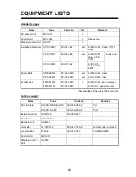
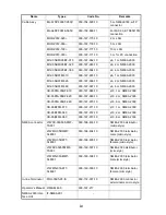
EQUIPMENT LISTS.................................................................................... iii

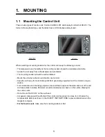
1. MOUNTING............................................................................................ 1
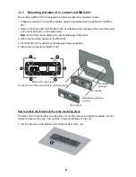
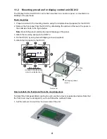
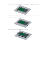
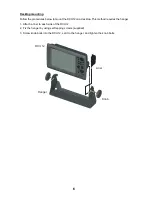
1.1

Mounting the Control Unit.............................................................................................1
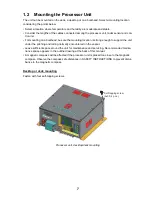
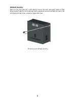
1.2

Mounting the Processor Unit ........................................................................................7

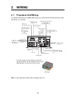
2. WIRING .................................................................................................. 9
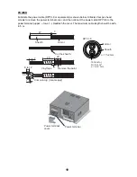
2.1

Processor Unit Wiring...................................................................................................9

2.2

Control Unit Wiring .....................................................................................................14

3. SETTING UP THE EQUIPMENT ......................................................... 15

3.1

Setup for Single MFD in the Network .........................................................................16

3.2

Setup for Multiple MFDs in the Network .....................................................................30

PACKING LISTS...................................................................................... A-1

OUTLINE DRAWINGS............................................................................. D-1

INTERCONNECTION DIAGRAM ............................................................ S-1

www.furuno.com

All brand and product names are trademarks, registered trademarks or their respective holders.

Summary of Contents for MFDBB

Page 1: ...the Processor Unit 7 2 WIRING 9 2 1 Processor Unit Wiring 9 2 2 Control Unit Wiring 14 3 SETTING UP THE EQUIPMENT 15 3 1 Setup for Single MFD in the Network 16 3 2 Setup for Multiple MFDs in the Network 30 PACKING LISTS A 1 OUTLINE DRAWINGS D 1 INTERCONNECTION DIAGRAM S 1 www furuno com All brand and product names are trademarks registered trademarks or their respective holders ...

Page 2: ......

Page 3: ... Observe the following compass safe distances to prevent interference to a magnetic compass ELECTRICAL SHOCK HAZARD Do not open the equipment unless totally familiar with electrical circuits Only qualified personnel should work inside the equipment Turn off the power at the switchboard before beginning the installation Fire or electrical shock can result if the power is left on Be sure that the po...

Page 4: ...PSU and rectifiers 3 Max two units total PROCESSOR UNIT MPU 001 RADAR SENSOR DRS4A DRS6A DRS12A DRS25A OR RADAR SENSOR DRS2D DRS4D FISH FINDER DFF series ETR 6 10N ETR 30N FCV 1150 Matrix for radar model PSU and rectifiers DRS2D 4D 4A 6A 12A MPU 001 RU 1746B 2 DRS25A PSU 013 DRS25A PSU 013 Radar Model PSU Rectifier for MFDBB Rectifier for PSU Rectifier for MFDBB PSU DRS2D Not required RU 1746B 2 D...

Page 5: ...or DCU12 cables CP19 00801 Spare Parts SP19 00501 001 023 090 1 set For MPU 001 fuses SP19 00601 001 023 040 1 set For DCU 001 fuses Accessories FP19 01201 001 033 760 1 For MCU 001 panel remover FP19 01101 001 023 060 For DCU12 panel remover Name Types Code No Remarks DVI D Cable DVI D D SINGLELINK 000 149 054 10 5 m DVI D D S LINK 000 150 200 10 10 m External Buzzer OP03 136 000 086 443 Rectifie...

Page 6: ...7 969 10 φ10 2 m NMEA 2000 CB 05PM 05BF 060 000 167 970 10 φ10 6 m NMEA 2000 CB 05BFFM 010 000 167 971 10 φ10 1 m NMEA 2000 CB 05BFFM 020 000 167 972 10 φ10 2 m NMEA 2000 CB 05BFFM 060 000 167 973 10 φ10 6 m NMEA 2000 NMEA connector LTWSS 050505 FMF TS001 000 168 603 10 NMEA 2000 distributor micro style LTWMC 05BMMT SL8001 000 168 604 10 NMEA 2000 terminator male micro style LTWMC 05BFFT SL8001 00...

Page 7: ...e well ventilated Mount the unit where shock and vibration are minimal Keep the unit away from electromagnetic field generating equipment such as motors and gen erators For maintenance and checking purposes leave sufficient space at the sides and rear of the unit and leave slack in cables Minimum recommended space is shown on the outline drawing for the control units Do not mount the DCU12 on the ...

Page 8: ...vent breakage of the panel 3 Attach the mounting sponge to the MCU 001 4 Fix the MCU 001 by using four self tapping screws supplied 5 Attach the front panel to the MCU 001 How to detach the front panel from the mounting place To detach the front panel after mounting the unit use the remover supplied as below Do not attempt to remove it by any other method to prevent damage to the unit 1 Set the re...

Page 9: ...ht side notch 4 Insert the remover to the space at the one end of the unit and pull it to raise the panel slightly Repeat this procedure for the opposite side 5 Use the remover to raise the panel at the two notches on the upper side of the unit 6 Use your hands to detach the front panel at both sides of it ...

Page 10: ...e panel carefully to prevent breakage of the panel 3 Attach the mounting sponge to the DCU12 4 Fix the DCU12 by using four self tapping screws supplied 5 Attach the front panel to the DCU12 How to detach the front panel from the mounting place To detach the front panel after mounting the unit use the remover supplied as below Note that the front cover may be damaged if you do not follow the method...

Page 11: ...is for all notches on the lower side of the unit 3 Insert the remover to the space at the one side of the unit and pull the remover to raise the panel slightly Do the same for the opposite side 4 Use your hands to detach the front panel from the lower side ...

Page 12: ...the DCU12 on a desktop This method requires the hanger 1 Attach a liner to each side of the DCU12 2 Fix the hanger by using self tapping screws supplied 3 Screw knob bolts into the DCU12 set it to the hanger and tighten the knob bolts DCU12 Hanger Knob Liner ...

Page 13: ...ong enough to support the unit under the pitching and rolling normally encountered on the vessel Leave sufficient space around the unit for maintenance and servicing Recommended mainte nance space appears in the outline drawing at the back of this manual A magnetic compass will be affected if the processor unit is placed too close to the magnetic compass Observe the compass safe distances in SAFET...

Page 14: ...on the bulkhead Screw in two 6x30 self tapping screws at upper fixing positions leaving 5 mm protruding Set the processor unit to the screws and screw in two self tapping screws at lower positions Tighten all screws Processor unit bulkhead mounting 4 pcs ...

Page 15: ...ces External speaker NMEA 2000 equipment SC 30 FI 50 GP 330B etc For USB speaker and microphone connections appropriate cables should be fastened to the metal plate beneath of connectors by the cable tie Metal plate DPYC 6 cable within 5 m 2 5C2V or 3C2V coaxial cable DVI D D SINGLELINK 5 m supplied with DCU12 10 m option MOD Z072 cable 5 m supplied with MCU 2 m 10 option 7 pin MJ A7SPF0007 5 m op...

Page 16: ... then connect the power cable DPYC 6 to the power terminal upper lower Reattach the cover The maximum cable length should be with in 5 m Conductor S 6 mm φ 3 12 mm 2 DPYC 6 Armor Sheath φ 15 2 mm 47 3 7 Armor Cut the sheath Vinyl tape Sheath 20 1 Crimp on lug local supply 20 Remove the paint 5 5 8 to 12 Power terminal cover Power terminal ...

Page 17: ...hen the LAN cable for DCU12 MCU 001 is connected to network 1 or 2 Note 1 When connecting PC s or FAR 2xx7 series radar confirm that the DIP switch es corre sponding to the PC port s are turned OFF Note 2 The MCU 001 s should be connected to the NETWORK 1 and or 2 port s directly not via the HUB 101 DIP switch ON OFF Front 1 2 3 4 NETWORK 1 2 3 4 ONLY MCU 001 DCU12 Binding screw M4x8 6 pcs ...

Page 18: ...hown below Pin No Color Function Remark Port No 18 Light green NET C IN 0V NMEA 2000 Power 17 Pink NET S IN 12V IN 16 Purple Shield 15 White BUZZER or EVENT IN External buzzer or event switch 14 Gray SPEED ALARM C Speed alarm contact 13 Yellow SPEED ALARM H 12 Black White 12V External buzzer power 11 Black GND 10 Blue White RD3 C Port 3 9 Blue RD3 H 8 Green White TD3 B 7 Green TD3 A 6 Orange White...

Page 19: ...l Standard JIS or the equivalent coaxial cable impedance 75Ω 3C 2V cable sectional view Video interface devices digital type The NavNet 3D can display digital pictures from IP cameras AXIS model 212 or 207 only via LAN IP addresses are allocated 172 31 200 003 through 006 For details see the Operator s Manual for model 212 and 207 Insulator Shield Vinyl sheath Conductor S 0 19 mm 0 5 mm 2 ...

Page 20: ...able through the DVI cover supplied and fixing plate supplied in that order 2 Attach the DVI cable to the DVI connector at the rear of the DCU12 and then tighten the thumbscrews on the connector 3 Slide the DVI cover so that it covers the connector at the rear of the display control unit 4 Put the fixing plate over the DVI cover and then fasten it with four binding screws supplied 5 Pass the cable...

Page 21: ...28 Own tab Set the NMEA 0183 2000 and Analog video devices connected to your MFD Global tab Set data on the network These data can be shared with MFDs on the network Sounder tab This tab appears when a network sounder DFF ETR series or FCV 1150 is connected Set the items for frequencies and TD ID transducer of Airmar as appropriate Radar tab This tab appears when a radar sensor DRS series or FAR 2...

Page 22: ... and push the left click button Note that the language of the Installation Wizard is English regardless of language setting And press the Next key The system counts the number of sounders radars and other sensors you have connected and displays the results Allow the system to count the number of sensors which takes about 30 sec onds The following menu appears 2 Confirm that the Master DHCP Server ...

Page 23: ... Same picture is shown on two displays Extended The picture is split to two screens as below Left side picture Picture from the display connected to the DVI 1 port Right side picture Picture from the display connected to the DVI 2 port 6 Choose the DVI resolution of the display unit Auto SVGA XGA or SXGA at the DVI Resolution pull down menu 7 Click the Next button Dual Display mode setting SVGA XG...

Page 24: ...er 127250 Vessel Heading 127251 Rate of Turn 127257 Attitude 127258 Magnetic Variation 127259 Speed Water referenced 128267 Water Depth 129025 Position Rapid Update 129026 COG SOG Rapid Update 129029 GNSS Position Date 129033 Time Date 129283 XTE 129284 Navigation Data 130306 Wind Data 130310 Environmental Parameters 130311 129540 GNSS Sats in view 129285 Navigation Route WP information 130577 Dir...

Page 25: ... operation to complete the nicknames 9 Set baud rate at the Baudrate pull down menu 4800 or 38400 10 Choose how to indicate waypoints Name or ID No at the WPT ID Format pull down menu 11 Choose the pilot mode Generic or Zeus at the Pilot Mode pull down menu Generic NAVpilot 500 or other auto pilot Zeus Mercury Zeus electronic steering Note When choosing Zeus at one of NMEA0183 ports 1 to 3 Generic...

Page 26: ...vanced Setup button to show the set ting menu for GP 320B Set all items referring to the table shown below NMEA0183 Output sentences Name Meaning Name Meaning AAM Waypoint arrival alarm RMA Loran C data APB Autopilot sentence RMB BOD Bearing origin to destination RMC GPS Transit BWC BWR Bearing and distance to waypoint VHW Speed heading through water DBT Depth below transducer VTG Speed over groun...

Page 27: ...is broadcasting abnormal satellite number s in its Alma nac which contains general orbital data about all GPS satellites including those which are malfunctioning Using this information the GPS receiver automatically eliminates any malfunctioning satellite from the GPS satellite schedule However the Almanac sometimes may not contain this information If you hear about a malfunctioning satellite from...

Page 28: ...e the desired unit of length and width for the boat ft m at the Length Width Height unit pull down menu 21 Set the length of boat at the Boat length pull down menu 22 Set the width of boat at the Boat Width pull down menu 23 Choose the number of engines on your boat 1 2 or 3 at the Number of Engine pull down menu 24 Choose the max scale of the tachometer 3000 rpm 4000 rpm or 8000 rpm at the Engine...

Page 29: ...nd push it to confirm selection Repeat this operation to complete the nicknames To update the nickname information on the network click the Refresh button 28 Click the Next button Global IP Camera tab The IP cameras connected to the network are assigned a name IPcamera1 to 4 If you don t like the preassigned name you can change it here Change the name using the cursor pad and RotoKey as is the Glo...

Page 30: ...ot go to step 31 Item Description Position SOG COG Choose the position fixing sensor to use GP 320B GP 310B etc Heading Choose the heading sensor to use SC 30 PG 500 etc Speed Through Water Choose the speed STW sensor to use DFF etc Water Depth Choose the depth sensor to use DFF etc Water Temperature Choose the temperature sensor to use DFF etc Wind Choose the wind sensor to use FI 303 501 WS 200 ...

Page 31: ...own menu and choose Model Number TD ID or Manual according to the transducer connected Model Number Furuno s transducer TD ID Airmar s transducer w TD ID Manual Transducers other than above b If you choose Model Number at step a click the High Frequency and Low Frequency pull down menus and choose the applicable model type For TD ID and Manual set the high and low frequencies c For DFF1 or DFF1 UH...

Page 32: ...port starboard direction When the transducer is located on the starboard side set a positive value e Click the Motion Sensor pull down menu and choose SC 30 or SC 50 110 if connected f Set the transducer position at the Transducer Position pull down menus g If the DFF3 is equipped with a water temperature sensor click the Temperature Port pull down menu and choose the temperature source MJ NMEA018...

Page 33: ...o b If you choose Model Number at step a click the High Frequency and Low Frequency pull down menus and choose the applicable model type For Manual set the high and low fre quencies with the respective pull down menus c Use the arrow buttons at Transducer Position to set transducer position d If a radar sensor is connected click the Next button to continue For FCV 1150 Do the step c shown above Or...

Page 34: ...u will probably observe some small errors on the display because of the diffi culty in achieving accurate initial positioning of the radar sensor The following adjustment will compensate for this error a Set ship s heading toward a suitable target for example ship or buoy b Click the Range pull down menu and choose a range between 0 125 and 0 25 nautical miles c Click the Push TX button to transmi...

Page 35: ...s near the surface The width of the line changes with transducer used and installation characteristics If the width of the line is 1 0 m or more set the line area as below 1 At the normal operation mode press the MENU key while pressing the CNTRL key down to open the Serviceman menu 2 Rotate the Rotokey to choose the Fish Finder tab and push the Rotokey 3 Rotate the Rotokey to choose Zero Line Rej...

Page 36: ...9 Set up the next MFD as follows a Press the POWER key to turn the power on b Choose language and click the Next button c Choose OFF from the Master DHCP Server setting box d Set up the MFD using the Installation Wizard and wait for the other MFD s setting are fin ished 10 Set up other MFDs 11 After setting up all MFDs click the Save and Exit button on the master MFD and the unit goes off automati...

Page 37: ... 7 6 0 5 4 26 10 1 ͳ 3 6 70 6 ᓮㇱ 241 5514 70 6 27 ຠ 52 4 2 465 ຠ 52 4 2 465 52 Ꮏ ᢱ 056 6 10 6 4 5 2 㩃㨺㩖㩨㩣 ຠ 55 47 Ꮏ ᢱ 056 6 10 6 4 5 2 ᦠ 1 7 06 㩕㨷㨺㩇㩨ᄌᦝߩ߅㗿 016 6 10 1 7 06 ขᛒ ᦠ 12 4 614 5 07 1 ᠲ ⷐ㗔ᦠ 㩊㩃㩨㩧 12 4 614 5 7 ⵝ ⷐ㗔ᦠ 056 6 10 07 ขᛒ 12 4 614 5 07 0 80 6 1 41 0 80 6 41 ᦠ㘃㩃㨺㩇 1 7 065 5 9 6 9 6 㪈㪅䍘㪄䍢䍼 ภᧃየ䈱㪲㪁㪁㪴䈲䇮ㆬᛯຠ䈱ઍ 䍘䍎䍢䍼䉕 䈚䉁䈜䇯 㪚㪦㪛㪜㩷㪥㪬㪤㪙㪜㪩㩷㪜㪥㪛㪠㪥㪞㩷㪮㪠㪫㪟㩷㩹㪁㪁㩹㩷㪠㪥㪛㪠㪚㪘㪫㪜㪪㩷㪫㪟㪜㩷㪚㪦㪛㪜㩷㪥㪬㪤㪙㪜㪩㩷㪦㪝㩷㪩㪜㪧㪩㪜㪪㪜㪥㪫㪘㪫...

Page 38: ...㪦㩷㪫㪰㪧㪜㪪㩷㪘㪥㪛㩷㪚㪦㪛㪜㪪㩷㪤㪘㪰㩷㪙㪜㩷㪣㪠㪪㪫㪜㪛㩷㪝㪦㪩㩷㪘㪥㩷㪠㪫㪜㪤㪅㩷㩷㪫㪟㪜㩷㪣㪦㪮㪜㪩㩷㪧㪩㪦㪛㪬㪚㪫㩷㪤㪘㪰㩷㪙㪜㩷㪪㪟㪠㪧㪧㪜㪛㩷㪠㪥㩷㪧㪣㪘㪚㪜㩷㪦㪝㩷㪫㪟㪜㩷㪬㪧㪧㪜㪩㩷 㪧㪩㪦㪛㪬㪚㪫㪅㩷㪨㪬㪘㪣㪠㪫㪰㩷㪠㪪㩷㪫㪟㪜㩷㪪㪘㪤㪜㪅 A 3 1 01 6 2 2 ޓޓ 176 0 ฬ ޓޓ 0 ᢙ 3 6 ㅜ㧛 4 4 5 ภ 01 ဳฬ㧛ⷙᩰ 5 4 26 105 056 6 10 6 4 5 Ꮏ ᢱ 27 58 58 5 㩎㩡㩇㩊㨹㩕㩩㩧㩒㩆㩨 ޓ 㩆㨷 5 6 22 0 5 4 9 575 1 01 㩄㩧㩗㩨㨹㩂㩇 ޓ 6 8 0 1 01 㧔 ߩኸᴺߪ ޔ ෳ ୯ߢߔ ޓޕ 05 105 0 4 9 0 14 4 4 0 10 㧕 㧲㨁㧾㨁㧺㧻 ޓ 㧱㧸㧱㧯㨀㧾㧵㧯 ޓ 㧯㧻 ޓ 㧚㧘㧸㨀㧰 ဳᑼ 㩄㨺㩎㩨 ภ߇㧞Ბߩ႐ว ޔ ਅᲑࠃࠅ Ბߦઍࠊࠆㆊᷰ...

Page 39: ...㧘㧸㨀㧰 ဳᑼ 㩄㨺㩎㩨 ภ߇㧞Ბߩ႐ว ޔ ਅᲑࠃࠅ Ბߦઍࠊࠆㆊᷰᦼຠߢ ࠅ ޔ߅ߥޓޕߔ ߡߞ ߇߆ࠄߜߤޔ ຠ ߪᄌࠊࠅ ߖ ࠎ ޕ 691 6 2 5 0 1 5 56 14 0 6 6 19 4 241 7 6 5 22 0 2 1 6 722 4 241 7 6 37 6 5 6 5 A 6 1 01 6 2 2 ޓޓ 176 0 ฬ ޓޓ 0 ᢙ 3 6 ㅜ㧛 4 4 5 ภ 01 ဳฬ㧛ⷙᩰ 5 4 26 105 056 6 10 6 4 5 Ꮏ ᢱ 7 㩙㨽㩧㩎㩔㩩㨹㩁㩧 2 0 1 01 㩎㩡㩇㩊㨹㩕㩩㩧㩒㩆㩨 ޓ 㩆㨷 5 6 22 0 5 4 9 575 1 01 㧔 ߩኸᴺߪ ޔ ෳ ୯ߢߔ ޓޕ 05 105 0 4 9 0 14 4 4 0 10 㧕 㧲㨁㧾㨁㧺㧻 ޓ 㧱㧸㧱㧯㨀㧾㧵㧯 ޓ 㧯㧻 ޓ 㧚㧘㧸㨀㧰 ဳᑼ 㩄㨺㩎㩨 ภ߇㧞Ბߩ႐ว ޔ ਅᲑࠃࠅ ...

Page 40: ...ޔ ਅᲑࠃࠅ Ბߦઍࠊࠆㆊᷰᦼຠߢ ࠅ ޔ߅ߥޓޕߔ ߡߞ ߇߆ࠄߜߤޔ ຠ ߪᄌ ࠊࠅ ߖࠎ ޕ 691 6 2 5 0 1 5 56 14 0 6 6 19 4 241 7 6 5 22 0 2 1 6 722 4 241 7 6 37 6 5 6 5 A 8 1 01 6 2 2 ޓޓ 176 0 ฬ ޓޓ 0 ᢙ 3 6 ㅜ㧛 4 4 5 ภ 01 ဳฬ㧛ⷙᩰ 5 4 26 105 5514 5 ઃዻຠ 7 7 㩔㩩㩒㩣㩢㩛㨺㩔㩨㨺 2 0 4 18 4 1 01 㩖㨲㩣㩊㨺㩂㩢㨺㩏㨺 0 0 16 1 01 㧔 ߩኸᴺߪ ޔ ෳ ୯ߢߔ ޓޕ 05 105 0 4 9 0 14 4 4 0 10 㧕 㧲㨁㧾㨁㧺㧻 ޓ 㧱㧸㧱㧯㨀㧾㧵㧯 ޓ 㧯㧻 ޓ 㧚㧘㧸㨀㧰 ဳᑼ 㩄㨺㩎㩨 ภ߇㧞Ბߩ႐ว ޔ ਅᲑࠃࠅ Ბߦઍࠊࠆㆊᷰᦼຠߢ ࠅ ޔ߅ߥޓޕߔ ߡߞ ߇߆ࠄߜߤޔ ຠ ߪᄌࠊࠅ ...

Page 41: ... 1 5 56 14 0 6 6 19 4 241 7 6 5 22 0 2 1 6 722 4 241 7 6 37 6 5 6 5 A 10 1 01 6 2 52 6 01 0 1 2 46 176 0 9 01 14 2 4 5 6 2 4 8 5 52 4 914 0 37 06 6 4 4 5 1 01 1 01 2 5 2 01 52 4 2 465 56 14 7 5 5 65 2 4 8 55 6 2 01 7 㩕㨷㨺㩇㩨 8 2 75 55 67 6 2 4 5 0 74701 64 1 6 9 01 㧔 ߩኸᴺߪ ޔ ෳ ୯ߢߔ ޓޕ 05 105 0 4 9 0 ޓ 14 4 4 0 10 㧕 2 ဳᑼ 㩄㨺㩎㩨 ภ߇㧞Ბߩ႐ว ޔ ਅᲑࠃࠅ Ბߦઍࠊࠆㆊᷰᦼຠߢ ࠅ ޔ߅ߥޓޕߔ ߡߞ ߇߆ࠄߜߤޔ ຠ ߪᄌࠊࠅ ߖࠎ ޕ 691 6 2 5 0 1 5 56 1...

Page 42: ...8 Aug 2012 Y NISHIYAMA ...

Page 43: ...Jun 27 07 R Esumi ...

Page 44: ...Oct 22 07 R Esumi ...

Page 45: ...Oct 22 07 R Esumi ...

Page 46: ... A0 59A2 59A0 2 2 52 4 412 10 241 5514 70 6 27 ᓮㇱ ᄖㇱࡕ 6 40 10 614 7 Ṷ ㇱ 241 5514 70 6 27 294A59A0 294A59A2 A6 A2 A6 A0 A4 A2 A4 A0 2 4 0 6914 8 59A2 59A0 8A176A2 0 5 52 219 4 176 8 US 4 A6 A2 A6 A0 A4 A2 0 6914 A4 A0 0 1 O Ǿ 2 2 2 2 2 2 4 A6 A2 A6 A0 A4 A2 A4 A0 0 8 2 885 Z O 9 6 㩆㩥 A6 A2 A6 A0 A4 A2 A4 A0 0 4 8A176A2 0 O 1 59 A6 A2 A6 A0 A4 A2 A4 A0 0 4 0 8 06 00 70 6 6 A 8A 1 8 US 6 A 8A 16 0 6 ...

Page 47: ......

Page 48: ...nual is elemental chlorine free FURUNO Authorized Distributor Dealer 9 52 Ashihara cho Nishinomiya 662 8580 JAPAN A APR 2008 Printed in Japan All rights reserved D JUN 19 2013 Pub No IME 44460 D REFU MFDBB 0 0 0 1 6 7 2 2 2 1 3 ...

Reviews: