background image


FEG−881

OPERATION MANUAL


8 INCH COLOR GPS・PLOTTER・FISH FINDER


Summary of Contents for FEG-881

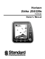
Page 1: ...FEG 881OPERATION MANUAL 8 INCH COLOR GPS PLOTTER FISH FINDER...

Page 2: ...ursor Setup 67 2 5 How to set up Track of Ship Position 2 6 Simulation 68 2 7 How to set up Miscellaneous 69 3 System 71 3 1 Satellite Information 71 3 2 How to print out Display 3 3 How to test Keybo...

Page 3: ...nding temperature An airy place avoid place for much vibration and shock avoid generate magnetism or dislike not attached in near place length of code are better to longer for maintenance and check pe...

Page 4: ...on distance location or topography The Global Positioning System GPS is operated by the United States government which solely responsible for its accuracy and maintenance The government s system is su...

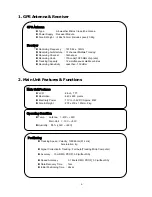
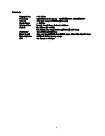
Page 5: ...1 This chapter provides an overview of the GLOBAL POSITIONING SYSTEM GPS 1 GPS PLOTTER...

Page 6: ...uire the position Once the GPS Plotter has received an accurate fix from the satellites ship s position bearing time speed and other operations can be calculated GPS Global Positioning System has two...

Page 7: ...3 2 Features This chapter provides Features of GPS Plotter GPS Antenna Receiver Main Unit Features Functions Standard Components 2 FEATURES...

Page 8: ...y 12 simultaneous satellite vehicles Receiving Sensitivity Less than 130 dBm Positioning Tracking Speed Velocity 1000Knots 514 m s Acceleration 4g Signal Correction Tracking Full Auto Tracking Micro C...

Page 9: ...16colors Memory 10 000points Distinguish color delete User s Line Drawing Mark 9 980 points Waypoint Route Memory 20 routes 1 route 20 points possible to use both way PLOTTER FUNCTION Auxiliary Memory...

Page 10: ...ps Depth Ranges 0 1 500m Display Modes Normal Pursuit Zoom Bottom Lock Zoom Alarms Keel Alarm 0 999m Fish Alarm can change to Strong Middle Weak 3 steps Anti Clutter Strong Middle Weak 3steps Image Sp...

Page 11: ...881 1EA 2 GPS Antenna GPS 18 1EA With spacer code10m 3 Stand MP 881 1EA Installed to unit 4 Power Cable CVV SB 0 75 SQ MM x 2C 3m O881A 5 Spare Fuse 3A X 2 24V 7A X 1 12V 3EA 6 Knob bolts M6 X 20 2EA...

Page 12: ...8 3 Device Display This chapter provides Device Display about GPS Plotter Display Device Remote Controller Power ON OFF Menu Plotter 3 Device Display...

Page 13: ...t Left User Data Load Back up C Map card slot Right Load C Map chart SD card slot Under Own ship move to the center Change Mark type Track ON OFF in Plotter Display Course Up ON OFF Waypoint Route Nav...

Page 14: ...10 Power ON OFF Power ON Press Power OFF Press and hold approximately 2 sec Note Power Button on Main Unit is always active but on remote control is active when wire connected to main unit only...

Page 15: ...YPE 2 SET 1 NAVIGATION SET 2 ALARM SET 3 OWN SHIP SET 4 CURSOR SET 5 SHIP TRACKING 6 SIMULATION 7 ETC SET 3 SYSTEM 1 SATELLITE INFO 3 KEYBOARD TEST 4 SYSTEM SET 5 SYSTEM INFO 4 FISH 1 SCREEN SPEED 2 N...

Page 16: ...Plotter Display Only y Display mode change at Plotter Fishfinder Display A own ship position certainly serves as the destination number 0000 and destination 0000 cannot edit Fishfinder Plotter Naviga...

Page 17: ...13 GPS Plotter Display 28 2 3 1 4 7 21 22 5 10 12 13 14 15 17 18 16 27 11 8 19 20 23 24 25 26 6 9...

Page 18: ...current cursor position 13 Longitude of Cursor Longitude of current cursor position 14 Distance to Cursor Distance between current position and cursor 15 Cursor direction from An own ship The Directio...

Page 19: ...15 C MAP Plotter Display 2 3 1 4 7 21 22 5 10 12 13 14 15 17 18 16 27 11 8 19 20 23 24 25 26 6 9...

Page 20: ...e of Cursor Latitude of current cursor position 13 Longitude of Cursor Longitude if current cursor position 14 Distance Distance between current position and cursor 15 Bearing Bearing from own ship to...

Page 21: ...17 Day Night Mode in Plotter Display Press Open the menu such as Transparency Day Night mode...

Page 22: ...18 Navigation Display In Navigation Display Press You can see Own ship s position Speed Bearing in full screen which is helpful for your sailing...

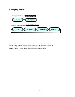
Page 23: ...19 Fish finder Combo Display Fish finder Display...

Page 24: ...20 4 Operating Instruction This chapter provides Operating Instruction in FEG 881series DATA SET SYSTEM FISH FINDER 4 Operating Instruction...

Page 25: ...e 1 DATA 1 TRACK DATA 1 SET in order o Set the below items used by Direction Number button y 1 STORE Select ON OFF y 2 SELECT Select TIME DISTANCE of Track save y 3 TIME 2 SELECT Input to set time y 4...

Page 26: ...2h 1 min 333h 19m 13days 21h 5 min 1666h 35m 69days 10h 10 min 3333h 10m 138days 21h 30 min 9999h 30m 416days 15h 60 min 19999h 833days 7h NOTE Track save ON OFF set Select ON to be saved and drawn cu...

Page 27: ...he Vessel n Press Move 1 DATA 1 TRACK DATA 2 CLEAR o Select one of below TRACK CLEAR method Press y 1 ALL TRACK Clear all Track line y 2 COLOR Clear Each color of Track line p Display Clear confirm Se...

Page 28: ...ALC Use this function to calculate the Vessel s Track n Press Move 1 DATA 1 TRACK DATA 3 CALC o After selecting below TRACK CALC Press y 1 ALL TRACK Calculate all memory Track 2 COLOR Calculate each c...

Page 29: ...q Select the device to be saved Press y Internal ROM Only one file save available y C User CARD Multiple file save available y COM PORT Available to transfer thru RS 232 to the other SYSTEM save y SD...

Page 30: ...mit ted in case of Internal ROM COM PORT o Press Move 1 DATA 1 TRACK DATA 5 LOAD p Select the files to be load from Storage Select q After selecting file name Press Once you load the saved TRACK file...

Page 31: ...at has files to be erased Internal ROM is non available o Press Move 1 DATA 1 TRACK DATA 6 ERASE p Select the device which has files to be erased at Storage Select q Select file name Press display Era...

Page 32: ...ATA 2 MARK DATA 1 SELECT o Select MARK its color using by Direction key On the screen Use to select MARK To select Color Press Select 1 M COLOR and Push which is the other pass NOTE Selecting DRAW MAR...

Page 33: ...osition y 2 LAT LON Append MARK at indicated Latitude Longitude position p When it is selecting 2 LAT LON Input the figures of LAT LON using by direction key After moving cursor to the MARK to be eras...

Page 34: ...n 2 ship position 2 Press Move cursor Press to input easier NOTE MARK Management User needs to manage its color before input MARK Then you may erase it easier after you need to Further you d better sa...

Page 35: ...y 1 ALL MARK Clear all MARK y 2 SHIP POS Clear Mark on own ship s position y 3 COLOR Clear MARK in color y 4 LAT LON Clear MARK in a value of Lat Lon p In a selection 4 LAT LON after input the value b...

Page 36: ...select things to be saved and then press button y Internal ROM Possible to save only one file y C User CARD Possible to save several files y COM PORT Possible to send to another SYSTEM through RS 232...

Page 37: ...ol to be called a file Possible to omit when using Internal ROM COM PORT o Press button and move 1 DATA 2 MARK DATA 5 LOAD p Select a storage tool into STORAGE SELECT q After select a file name and pr...

Page 38: ...o Press button and move 1 DATA 2 MARK DATA 6 ERASE p Select a storage tool having a file to be erased from STORAGE SELECT q After select a file name and then press button in order to show Erase Confi...

Page 39: ...line drawn by a user into a Plotter screen In setting ON the coastal line is displayed in a function of 1 3 2 Coastal Line Drawing in advance n Press button and move 1 DATA 3 USER S LINE 1 DISPLAY o...

Page 40: ...g start by using a direction button and press button then after move the cursor to a point to be connected and press button Then the coastal line is keeping connection In order to jump the coastal lin...

Page 41: ...file name q After select a tool to be saved press button y Internal ROM Possible to save one file only y C User CARD Possible to save several files y COM PORT Possible to send another SYSTEM through R...

Page 42: ...to be called a file Possible to omit when using Internal ROM COM PORT o Press button and move 1 DATA 3 USDE S LINE 4 LOAD p Select a storage tool into STORAGE SELECT q After select a file name and pr...

Page 43: ...s button and move 1 DATA 3 User Line 6 Erase p Select a storage tool having a file to be deleted from STORAGE SELECT q After select a file name and then press button in order to show Erase Confirm and...

Page 44: ...oint that the user registered into a Plotter screen In setting ON the waypoint is marked in a function of 1 4 2 Waypoint Edit in advance n Press button and move 1 DATA 4 WAYPOINT DATA 1 DISPLAY o Afte...

Page 45: ...0 to 9999 n Press button and move 1 DATA 4 WAYPOINT DATA 2 EDIT o After move the cursor to a waypoint number by using a direction button and press button If press and buttons the registered waypoint c...

Page 46: ...ton the waypoint coordinates can be registered with ease NOTE How to delete for Registered Waypoint Data n After select the waypoint number without Lat Lon into Waypoint Edit it can be converted by pr...

Page 47: ...s Numbers can be possible only in file name q After select a tool to be saved press button y Internal ROM Possible to save one file only y C User CARD Possible to save several files y COM PORT Possibl...

Page 48: ...using Internal ROM COM PORT o Press button and move 1 DATA 4 WAYPOINT DATA 4 LOAD p Select a storage tool into STORAGE SELECT q After select a file name and press button However be advised that the w...

Page 49: ...ress button and move 1 DATA 4 WAYPOINT DATA 5 ERASE p Select a storage tool having a file to be erased from STORAGE SELECT q After select a file name and then press button in order to show Erase Confi...

Page 50: ...sible to register to a route DATA n Press button and move 1 DATA 5 ROUTE DATA 1 EDIT o Select waypoint number by using a direction button press button p After select the waypoint to be registered in a...

Page 51: ...uired number and then press button J Jump character is shown in beside of the waypoint number and it can be exempted from a waypoint route temporarily In case of release press button once more in orde...

Page 52: ...rt C USER card for a format p After insert C USER card press button It takes around 5 minutes for a format If the Disc with Data is making a format all data is deleted and it cannot recover You must p...

Page 53: ...form and symbol for seabed displayed on the plotter chart n Press button after move 1 DATA 7 SEABED TYPE and then press button NOTE Display Calendar on the screen n Navigation or Plotter screen Press...

Page 54: ...o replace the plotter program in a main after call the newest plotter program saved into a storage tool n Insert a storage tool with a newest Plotter program o After press button and move 1 DATA 7 PRO...

Page 55: ...WAYPOINT NAVIGATION o After select The start point of Waypoint number of the left and then press button 0000 number shows an own ship s position and 0001 9999 is belongs to the registered waypoints p...

Page 56: ...efer to 2 1 4 EXIT WPT RTE ANCHOR NOTE Watch Set Up It is an opposite notion against the waypoint navigation After memory of a certain of the position this function is used to return the position duri...

Page 57: ...tered in 1 5 1 Route Edit with n Press button and move 2 SET 1 NAVIGATION SET 2 ROUTE NAVIGATION o After select a route number by using a direction button press button In case of reverse navigate afte...

Page 58: ...a bright grey line The Lat Lon approach speed direction distance and time of the navigating route point are shown in a bottom left of the plotter screen Refer to Chapter 3 5 Plotter Screen In order to...

Page 59: ...d set up a route navigation p After move the coordinates CURSOR to next waypoint set up by using a direction button press button You can repeat this method whatever you want to set up waypoints q If p...

Page 60: ...rotect a break away from an anchor range set up as inputting the position information of the current own ship It can be used with 2 2 3 ANCHOR ALARM n Press button and move 2 SET 1 NAVIGATION 3 ANCHOR...

Page 61: ...the Plotter screen are shown Refer to Chapter 3 5 Plotter Screen If the vessel breaks away from a range of anchor alarm the alarm sounds and the red circle blinks in order to advise of the vessel s b...

Page 62: ...Navigation Anchorage Setup and Monitoring Setup n Press button go through 2 SET 1 NAVIGATION SET 4 EXIT WPT RTE ANCHOR o Press button then the above shown navigational functions the anchorage setup th...

Page 63: ...ance of the preset final destination n Press button go through 2 SET 2 ALARM SET 1 ARRIVAL ALARM o Use button to select ON OFF In selecting ON use the number buttons to input Arrival Alarming Range 0...

Page 64: ...he preset course range on her way to the destination n Press button go through 2 SET 2 ALARM SET 2 XTE ALARM o Use button to select ON OFF In selecting ON use the number buttons to input the derailmen...

Page 65: ...owns ship gets out of the preset rang mostly due to the tidal wave the ocean weather etc n Press button go through 2 SET 2 ALARM SET 3 AHCHOR ALARM o Use button to select ON OFF In selecting ON use th...

Page 66: ...ble Alarming When under voyage the own ship can use the function to create an alarming where any underwater cables are installed n Press button go through 2 SET 2 ALARM SET 4 SEA CABLE ALARM o Press b...

Page 67: ...ators when it senses any specific water depth within the preset alarming range through the transducers It is available to input 1m 999m n Press button go through 2 SET 2 ALARM SET 5 DEPTH ALARM o Use...

Page 68: ...g This is a function to make an alarming when the equipment senses any fish school under voyage n Press button go through 2 SET 2 ALARM SET 6 FISH ALARM o Use button to select ON OFF and the signals o...

Page 69: ...Own Ship With this function it is available to set up a variety of information on the own ship n Press button go through 2 SET 3 OWN SHIP SET o Use the directional buttons button button to set up eve...

Page 70: ...e vessel type If the status of GPS receipt or the measured position value are poor this function can work on smoothing the widely changing values of the lat log ship speed bearing finally to display t...

Page 71: ...ect the size color shape and line y 1 CURSOR SIZE Big Small y 2 CURSOR COLOR Green Blue Red y 3 CURSOR SHAPE Thin Thick y 4 CURSOR LINE ON OFF ON Press button to have the plotting cursor in blue color...

Page 72: ...a required for the real navigation to look as if ships are under voyage on the Plotter Display n Press button go through 2 SET 6 SIMULATION o Use button to set up ON OFF to be used for Simulation y 1...

Page 73: ...How to set up Miscellaneous User can set up any additional functions on SYSTEM and Plotter n Press button go through 2 SET 7 ETC SET o Use the directional buttons button button to set up the items sho...

Page 74: ...tion NORTH EAST SOURTH WEST North direction based on the preset Plotter map 7 Position Print 00 Min 00 Sec 60 Min 00 Sec To print the own ship position speed bearing at the intervals of preset time Wh...

Page 75: ...lite Information This is to set up the related information on GPS and necessary for navigation n Press button go through 3 SYSTEM 1 SATELLITE INFO o Use the directional buttons button button to set up...

Page 76: ...For Korea 09 00 should be input 4 Setting 12 24 12Hour 24Hour User can set up the indication way of 24 hours or noon afternoon 12 hours time system 5 Speed Mode Low Mid High Average ship speed can be...

Page 77: ...Users can make a self test to see if the remote works okay n Press button go through 3 SYSTEM 3 KEYBOARD TEST o Whenever each button is pressed it is normal if the button is conversed on the screen I...

Page 78: ...up System Users can set up Input Output ports used for system AIS memory map language in use etc n Press button go through 3 SYSTEM 4 SYSTEM SET o Use the directional buttons and button to set up eac...

Page 79: ...le This is to receive the information on ship name MMSI ship speed from AIS mounted ships and display the information on the screen Refer to the next Chapter 4 Memory Clear Yes No This is to delete al...

Page 80: ...ality and by automatically adjusting the length of the heading according to the ship speed it is also easy to figure out the navigational information such as the moving speed together with other ships...

Page 81: ...ritime ID y IMO NO IMO number y DRAUGHT Draught y S TYPE Ship Type y DEST Destination y NAV Current Navigational Status y LAT Latitude y LON Current Longitude of Ship y SOG Speed y COG Course y HDG He...

Page 82: ...Stop then press button to make AIS function operate or stop on the screen In selecting Operate users can see AIS on the right top side of the screen Note AIS SET Before operating AIS function Speed S...

Page 83: ...directional buttons to select 2 DISPLAY SET then press button to see the sub menu on the screen that shows Ship Name MMSI Speed o Select the ship information of AIS to be displayed on the screen then...

Page 84: ...D or country code for the target to be set up on the screen then press button eg Japan MID 431 432 Korea MID 440 441 China MID 412 413 p Select the target color shown below with the directional button...

Page 85: ...then press button It is available to select any color for other ships that have MID or country code except the preset colors from 3 Target Color 1 through 8 Target Color 6 o Use the directional button...

Page 86: ...to set up each item shown below Sys Info Item Input Range Description 1 LCD MODE Sharp PVI 1 PVI 5 To set up the LCD model of SYSTEM Note It is advised that users normally should not work on setting u...

Page 87: ...play Select plotter fish finder display or fish finder display only by using Load a set menu by Reduce a size of fish finder display Magnify a size of fish finder display Set a size of fish finder dis...

Page 88: ...or display only for fish finder y Start Set Change a water depth of fish finder s recording display by pressing button y Range Set Set a water depth interval of fish finder s recording display by y Ma...

Page 89: ...85 Fish finder line homing magnification screen Use button to choose a display mode button for high freq low freq and button for line homing magnification screen...

Page 90: ...86 4 1 Screen moving speed A function to adjust a screen moving speed n Press and go to 4 FISH 1 SCREEN SPEED o Select one of Stop Low Mid High Super High by using direction cursor and press...

Page 91: ...se To erase an interfacing signal occurs periodically or temporally is shown as noise on fish finder display n Press and go to 4 FISH 2 NOISE ERASE o Select one of Off Low Mid High by using direction...

Page 92: ...or noise and response for unnecessary school of fish step by step It helps to recognize of big fish group with distinct display n Press and go to 4 FISH 3 COLOR ERASE o Select one of Off Low Mid High...

Page 93: ...adjust a transmitting output of supersonic wave transmitted from transducer n Press and go to 4 Fish 4 TX POWER SET o Select High Low and press In case of Low the output is automatically adjusted depe...

Page 94: ...DTH SET In response to range of depth and transmitting times adjust transmitting power by LOW and HIGH about automatic adjustment of pulse width n Press and go to 4 FISH 5 PULSE WIDTH o Select Low Hig...

Page 95: ...91 4 6 COLOR PATTERN SET Select a color to show a fish group and three colors available n Press and then go to 4 FISH 6 COLOR PATTERN o Select Pattern 1 Pattern 2 Pattern 3 and then press...

Page 96: ...92 4 7 A SCOPE SET A scope on or off n Press and then go to 4 FISH 7 A SCOPE SET o Select ON OFF and then press...

Page 97: ...om water surface to transducer on vessel bottom and input the distance value This value is a criteria line 4 FREQUENCY SET 5 AUTO DEPTH SET Dual Freq Low Freq High Freq Range Shift How to display fish...

Page 98: ...94 5 System Maintenance Diagnosis This Chapter describes a Maintenance and Diagnosis for NAVIS Series System Maintenance and Repair Diagnosis 5 5 System Maintenance Diagnosis...

Page 99: ...ck up the condition for all sorts of the cables Replace it with new one if it is damaged or cut off Earth Terminal and cable Check up the condition of the Earth terminal If it is rusted or defective r...

Page 100: ...g 1 Check LCD contact point 2 Clean contact point for LCD connector Position coordinator is inaccurate 1 Check whether WGS 84 is selected at Geodetic tool 2 Set the value 0 if compensating function fo...

Page 101: ...97 6 Appendix This Chapter describes the appendix related to the operation of the unit Appendix 1 Geodetic Datum Appendix 2 Packing List Appendix 3 Installation Drawings Appendix...

Page 102: ...orocco 18 Saudi Arabia 63 Midway Island 19 India Nepal 64 Nigeria 20 Philippines 65 Trinidao Tobago 21 England 66 Colbo Florence 22 Hari 67 Egypt 23 Djakarta 68 Oman 24 Malaysia Singapore 69 Canary Is...

Page 103: ...NO FEG 881 1 2 Mounting Bracket CODE NO MP 881 1 6mm 17 3 Knob CODE NO 2 SAN 60 CODE NO GPS 18 4 Antenna 1 RG58C U 10M 20M CVV SB 0 75 SQ MM x 2C CODE NO O881A 6 DC Power Cable 1 7A X 1 12V 8 Fuse 1...

Page 104: ...100 FEG 881 2 2 No Item External Feature Dimension Q tyCHK Remark NT 13 C MAP Card CODE NO C MAP OPTION 14 C USER Card CODE NO C MAP BAK OPTION...

Page 105: ...101 APPENDIX 2 CONNECTING PINS...

Page 106: ...102 DIMENSIONS need more than 100mm for service space in main body rear unit mm...

Page 107: ...103 INSTALLING TO THE MAIN BODY...

Page 108: ...R Bronze TRANSDUSER BOTTOM SOLDERING 3 4 TOP INSERT 6 4 3 2 1 5 8 2 5 6 8 1 3 TD1 W hite 4 GND shield 5 TD2 Red TD 881 Plastic 70 M22 120 37 core shield L 8000 connector 3 5 connector white black shie...

Page 109: ...e routed close to each other either GPS antenna should be mounted at the highest point of your boat in order to receive the Signals from satellites without any trouble If there is any obstruction arou...

Page 110: ...ng antenna when an obstacle is empty in antenna circumference I am thorough by the electric wave from the satellite and reception cannot to do side ranking time shorten and there is a threat that side...

Page 111: ...107...

Page 112: ...108 Marine Products Division 601 Fuseminami Bld 3 1 7 Ajiro Higashi Osaka Osaka Japan 577 0841 http www nakanoeng com...

Reviews: