background image

USB INTERFACE

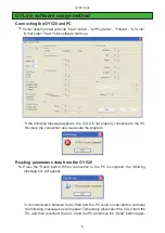
The operating parameters of the Futaba GY520 gyro can be set and changed from 
a PC by using this software. Since the Futaba CIU-2 USB adapter and power supply 
(receiver battery or 5V power source) are necessary, procure them beforehand and 
place into the state in which the CIU-2 is operated properly from the PC.

Note: The GY520 Link software is for Windows

®

 Vista/XP/2000 use and is 

not compatible with other OS.

Downloaded Zip file extraction (decompression)

 ..............................P2

GYLink software installation .............................................................P2

CIU-2 and GY520 connection .............................................................P4

GYLink software usage method .........................................................P5

Changing the parameters ....................................................................P8

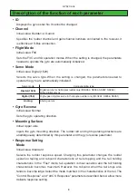
Description of the function of each parameter ..................................P9

Distribution & exemption of liability

• Futaba Corporation shall not be responsible for any damage caused by use of this software without 

regard to legal foundation. Use this software based on agreement to this.

• The copyright of this software and document resides with Futaba Corporation. Redistribution without 

the approval of the copyright holder is prohibited.

• Reverse engineering and modification of this software is strictly prohibited.

GY520 Link Software Manual

1M23Z00802

Summary of Contents for GY520

Page 1: ...ompression P2 GYLink software installation P2 CIU 2 and GY520 connection P4 GYLink software usage method P5 Changing the parameters P8 Description of the function of each parameter P9 Distribution exe...

Page 2: ...ng_V100 zip to the same location as the Zip file storage location GYLink msi file and setup exe file are extracted in the GYLink_Eng_V100 folder GY Link software installation Before installing the GYL...

Page 3: ...GY520 Link 4 Push the Next button 5 The install process begins 6 The installer displays the following after the install process Push the Close button...

Page 4: ...the USB port of the PC 2 Using the connection cord connect the 3 pin connector of the CIU 2 to the rudder input connector of the GY520 3 Connect the receiver battery or a 5V power source to the sensi...

Page 5: ...ly connected to the PC Recheck the connection and re execute the program Reading parameters data from the GY520 1 Press the Read button When connection to the PC is complete the following message box...

Page 6: ...eck the connections and then press the Write button again Reading parameters data saved at the PC 1 Select the Open command from the File menu 2 A file open dialog opens Select the file you want to op...

Page 7: ...PC by pressing the save button in the data save dialog Initializing the parameters data 1 Select the Initialize command from the File menu A confirmation message appears 2 When Yes Y is clicked the pa...

Page 8: ...tting an exact value the value can be changed in minimum units by PC cursor key operation 4 Set the Limit parameter after the gyro is mounted to the fuselage When the Enter button is pressed the setti...

Page 9: ...Digital 760 High speed digital servos for helicopter rudder only BLS251 S9256 S9251 Analog Analog servos Gyro Reverse Initial value Normal Sets the gyro operating direction Mounting Surface Initial U...

Page 10: ...rudder input changes Adjusting ranges are from 1 to 10 The value 10 is a most stiff of the pirouette control the value 1 is to be a moderate control Select with preferable rudder control style EXP Ini...

Page 11: ...0 setting range 30 100 Sets the gyro control basic gain When the set value is increased the gyro gain decreases For example if the set value is changed to 100 the gyro gain is halved If the transmitte...

Reviews: