background image

Instruction Manual

Outdoor Microphone System Types 41AM / 41CN

Skovlytoften 33, 2840 Holte, Denmark

www.gras.dk  gras@gras.dk


SOUND & VIBRATION

G R A S

. . . .

Summary of Contents for 41AM

Page 1: ...Instruction Manual Outdoor Microphone System Types 41AM 41CN Skovlytoften 33 2840 Holte Denmark www gras dk gras gras dk SOUND VIBRATION G R A S ...

Page 2: ...on 11 June 2010 LI0002 Outdoor Microphone System Types 41AM 41CN Note unless individually specified the term Outdoor Microphone System throughout this document refers to both types i e Type 41AM and Type 41CN ...

Page 3: ...Important any dismantling details given in this document are addressed solely to qualified service personnel who must ensure that the unit is first disconnected from its power supply before pro ceeding ...

Page 4: ...crophone Assembly 11 3 Access to Electronics Assembly 12 4 Calibration 14 4 1 Electrostatic Actuator 14 4 1 1 Adjustment 14 4 1 2 Calibration Control Box AC0001 14 4 2 Pistonphone 15 4 2 1 Setup and adjustment 16 4 3 Factory Calibration 16 5 Maintenance 17 5 1 Windscreen 17 5 2 Dehumidifiers 17 5 3 Multi frequency Calibration Check Optional 18 5 3 1 Output Connections 18 6 Service and Repair 19 7 ...

Page 5: ...1 4 1983 Type 1 requirements and can be used with any suitable electronic sound or vibration measurement system It is PTB approved as part of an IEC 651 Type 1 system A inch precision condenser microphone and thick film preamplifier ensure maximum stability and performance Both microphone and casing are made of stainless steel Precise in situ calibration checks at 1000Hz are enabled any time via a...

Page 6: ...long axis of symmetry Angle of incidence 0 Application monitoring airport noise Type 41CN Measurement reference direction horizontal perpendicular to axis of symmetry Angle of incidence 90 Application monitoring community noise See also Fig 1 2 Both types are almost physically identical differing only in the type of the microphone cartridge and rain protection cap used Type 41AM uses Microphone Ca...

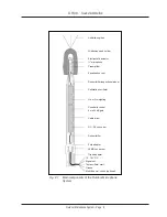
Page 7: ...ly of electronics and desiccator bags for absorb ing moisture The electronics include A switch mode power supply for generating a 200V for microphone polarisation b 120V for the microphone preamplifier And c an A weighting network d a circuit jumper for applying a gain of 20dB to the microphone signal A pole adaptor with a standard ISO 228 1 G1 in thread Also used for the tripod adaptor Fig 2 2 Th...

Page 8: ...d holder Electrostatic actuator microphone Preamplifier Equalisation vent Calibration oscillator Dehumidifier inspection window Lin or A weighting Sensitivity control 0 or 20dB gain Cable driver DC DC converter Dehumidifier Pole adapter LEMO connectror 12 18V DC Signal out Test oscillator start Ground Multi freq cal check optional Tripod adapter ...

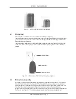
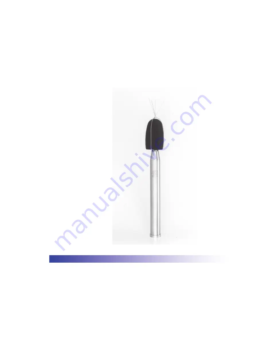
Page 9: ...vents smaller birds from perching between the other three spikes Fig 2 3 Windscreen of the Outdoor Microphone System 2 2 Microphone Assembly On delivery the microphone assembly is protected by a transport tube see Fig 2 4 A small hole of 0 5mm diameter at the top end of the transport tube ensures pressure equalization during transport The transport tube is also used when testing for self noise In ...

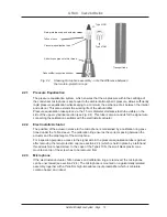
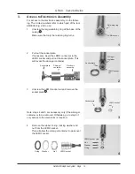
Page 10: ...under the Teflon sleeve The calibration ring ensures the correct spacing between the actuator and the diaphragm of the microphone For inspection purposes access to the signal wire in the pressure equalisation tube is gained after removing the rain protection cap see section 2 2 4 which is held in place by a left hand thread mushroom head screw In the case of the Type 41CN the small black plastic c...

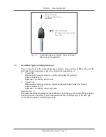
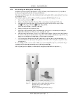
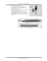
Page 11: ...ignal wire with gold plated pin from the top of the actuator housing so that it sticks directly out of the pressure equalisation tube 6 Use the special key RA0087 Fig 2 5 to unscrew the actuator housing right hand thread and remove the spacer and insulator rings placed around the microphone capsule Be very careful not to damage the diaphragm of the microphone capsule 7 The microphone capsule can n...

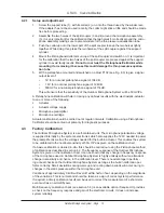
Page 12: ...ntainer to pass over the LEMO socket 2 Pull out the socket plate If necessary insert the LEMO connector in the LEMO socket and pull out the socket plate This will reveal the silica gel container 3 Unscrew the LEMO socket nut and remove the socket plate 5 Note steps 4 and 5 are necessary only if the silica gel container is to be removed Otherwise go to step 6 if only access to the electronics is re...

Page 13: ... container dried off and used again see section 5 2 6 Unscrew the stainless steel casing to give access to the electronics assembly If necessary remove the screw from the dehu midifier inspection window and screw the tommy bar AM0063 in its place if the casing is difficult to unscrew Dehumidifier container Stainless steel casing Electronics assembly 5 6 ...

Page 14: ...ly to simple absolute physical parameters The stability of this method ensures that the microphone calibration is consistent therefore no other calibration check is necessary Electrostatic actuator calibration should be carried out at regular intervals 4 1 1 Adjustment With the electrostatic actuator switched on adjust P201 see Fig 8 3 to give a signal output level of 31 6mV An electrostatic actua...

Page 15: ...o be used The RA0009 RA0041 consists of a support tube with a close fitting collar which holds together the two halves of a split coupler The two halves of the split coupler are engraved with a common number to show that they are correctly matched The correction values supplied with each RA0009 RA0041 must be applied to the nominal value for the Pistonphone or Sound Cali brator used means add mean...

Page 16: ...er Microphone cartridge Actuator calibration should be carried out at regular intervals Calibration using a Pistonphone Calibrator should be carried out primarily for diagnostic purposes 4 3 Factory Calibration The Outdoor Microphone System is a self contained unit The microphone polarisation voltage is supplied internally by the system s electronics which also supplies the 120V needed to power th...

Page 17: ...of the silica gel crystals in the bottom dehumidi fier If the top dehimidifier starts absorbing moisture then its time to change dry off the silica gel crystals in the bottom dehumidifier The effect of this will also dry off the silica gel crystals in the top dehumidifier There are two ways of drying off the silica gel crystals in the bottom dehumidifier 1 Unscrew the Plexiglas lid and put the deh...

Page 18: ...ircuit for amplification and then applied to the sys tem s electrostatic actuator built into the rain protection cap see Fig 2 4 As with the system s own calibration oscillator frequency doubling will take take place This option is useful for checking the stability of the system s frequency response It is not a measure of its free field frequency response 5 3 1 Output Connections The output connec...

Page 19: ...S Sound Vibration 6 Service and Repair Service and repair should be carried out only by qualified service personnel The Outdoor Microphone System should not be dismantled with power on because of the presence of high voltages in its circuits ...

Page 20: ... 5kHz 16kHz 1 5dB 5dB Dynamic range upper limit 156dB SPL at 20dB setting re 20µPa Total system noise level A weighted 20dB re 20µPa Lin 22 5Hz 22 5kHz 23dB re 20µPa Output impedance 50Ω Output current 25mA Power supply 12 18V DC Power consumption 120mA at 15V 180mA at 15V calibrator on Operating temperature range 40 C to 50 C Calibration level of electrostatic actuator 90dB re 20µPa at 1000Hz 0 2...

Page 21: ...phone adapter RA0009 Type 41AM RA0041 Type 41CN Foam windscreens 5 items AM0009 Calibration Control Box AC0001 Extension cables 3m AA0003 10m AA0002 20m AA0001 30m AA0017 50m AA0004 100m AA0015 200m AA0016 WEEE directive 2002 96 EC CE marking directive 93 68 EEC Manufactured to conform with RoHS directive 2002 95 EC G R A S Sound Vibration continually strives to improve the quality of our products...

Page 22: ...n 8 Circuit and Component Diagrams Fig 8 1 shows the circuit diagram for signal conditioning Fig 8 2 shows the circuit diagram for the power supply Fig 8 3 shows component placement and the location of user serviceable jumpers and adjust ment potentiometers ...

Page 23: ...Outdoor Microphone System Page 23 G R A S Sound Vibration Fig 8 1 Circuit diagram for signal conditioning ...

Page 24: ...Outdoor Microphone System Page 24 G R A S Sound Vibration Fig 8 2 Circuit diagram for power supply ...

Page 25: ...e location of user serviceable jumpers and adjustment potentiometers Jumper for gain 0 dB or 20 dB Jumper for gain 0 dB or 20 dB Jumper for response A weighting or linear Com not used Jumper for signal direct or conditioned Factory settings Potentiometer P102 Potentiometer P201 Potentiometer P101 Lin ...

Reviews: