background image


Pub. 43004-010H 

GAI-Tronics Corporation  400 E. Wyomissing Ave.  Mohnton, PA  19540  USA 

610-777-1374  

  800-492-1212  

  Fax:  610-796-5954 

V

ISIT WWW

.

GAI

-

TRONICS

.

COM FOR PRODUCT LITERATURE AND MANUALS


G A I - T R O N I C S ®   C O R P O R A T I O N  

A   H U B B E L L   C O M P A N Y  

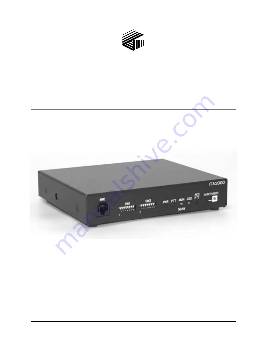
ITA2000A Series Tone Remote Adapter 

with Scanning 

User and Installation Manual 


*U.S. Patent 6,950,653 

Summary of Contents for ITA2000A Series

Page 1: ...USA 610 777 1374 800 492 1212 Fax 610 796 5954 VISIT WWW GAI TRONICS COM FOR PRODUCT LITERATURE AND MANUALS G A I T R O N I C S C O R P O R A T I O N A H U B B E L L C O M P A N Y ITA2000A Series Tone Remote Adapter with Scanning User and Installation Manual U S Patent 6 950 653 ...

Page 2: ...arranty obligations with respect to services exceed 100 of the total cost of services provided hereunder Limitations Exclusions The warranty on any equipment supplied hereunder is subject to Customer s use in compliance with applicable FCC regulations and manufacturer specifications The warranties herein shall not apply to and GAI Tronics shall not be responsible for any damage to the goods or fai...

Page 3: ...E PORT 8 Desk Microphone Port Pinout 8 TONE CONTROL INTERFACE 9 Scan Start Stop in the Scan Mode 10 Radio Monitor in Scan Mode 10 SUPERVISOR MODE 11 ACCESSORY OPERATION 11 TEST MODE 12 INSTALLATION 13 PLANNING THE INSTALLATION 13 MOUNTING 13 EQUIPMENT REQUIRED 14 Test Equipment 14 Documentation 14 CABLE INSTALLATION SAFETY CONSIDERATIONS 14 TELEPHONE LINE LIGHTNING AND OVER VOLTAGE PROTECTION 14 P...

Page 4: ...onventional 28 Switch Settings for SW2 Conventional 29 CONFIGURATION SWITCH SETTINGS FOR SCAN MODE OPERATION 30 Switch Settings for SW1 Scan 30 Switch Settings for SW2 Scan 31 LEVEL SETTINGS AND ADJUSTMENTS 32 Receive Audio Level 32 Line Output Level 32 Transmit Audio Level 33 TEST DIAGNOSTICS 34 THEORY OF OPERATION 35 TECHNICAL OVERVIEW 35 Transmit Audio 35 Radio Audio 35 Accessory Transmit 36 De...

Page 5: ... E Wyomissing Ave Mohnton PA 19540 US 800 492 1212 Outside US 610 777 1374 Service and Repair Inoperative or malfunctioning equipment should be returned to the factory for repair Please call 1 800 492 1212 to obtain a Return Authorization number published repair prices and shipping instructions A Return Authorization can also be obtained by visiting our website at www gai tronics com NOTE A purcha...

Page 6: ...eted areas dry environments and certain types of clothing silk nylon etc because they contribute to static build up Similarly disconnect the test probe prior to removing the ground lead 5 All electrically powered test equipment should be grounded Apply the ground lead from the test equipment to the circuit module before connecting the test probe 6 If a circuit module is removed from the system it ...

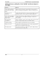
Page 7: ...ne cable Selectable timed or continuous monitor2 Flexible monitoring option Multiple parallel desk set support System flexibility and productivity are enhanced when several desk sets are connected 16 channel control1 Each of the five channel steer outputs can be used to change channels and other functions on certain radios Courtesy tones Sends a tone to the desk set when a mobile has stopped trans...

Page 8: ...llows remote scanning and radio control from multiple dispatch points Using regular leased lines multiple dispatchers can monitor and control scanning capability Each dispatch point displays currently active receive channel Flexible scanning configuration Number of channels scan rate scan stop time and scan resume can all be easily configured using readily accessible DIP switches Talk back scannin...

Page 9: ...lti channel steering capable radios Dispatch points are updated using these techniques through the use of the parallel status update feature found in the GAI Tronics Model ITR2000A and IPE2500A Desk Sets To accommodate radios that vary in their active input logic the ITA2000A can be set up to provide discrete active output logic functions Active low or active high outputs can be set for each radio...

Page 10: ...s nominal 10 dBm Logic outputs PTT CH STEER 20 mA 100 mW dissipated Maximum number of desk sets supported practical limit 10 Microphone connections Desk microphone Input tone tolerance 2 Safety Class III SELV powered equipment Powered by optional UL listed E104603 and CSA certified LR67888 ac adapter EMI USA FCC Part 15 Sub B Verification Canada ICES 003 Line Interface FCC Part 68 Exempt Category ...

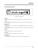
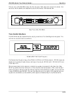
Page 11: ...nal The timed or constant monitor LED labeled MON illuminates when the ITA2000A is in the monitor mode Scan The SCAN LED blinks at the scan rate when the ITA2000A is scanning and is lit steadily when in monitor mode CSQ LED The CSQ LED illuminates when a carrier detect input is active ACC PTT LED The ACC PTT LED illuminates when the accessory PTT input is active SUPERVISOR LED The SUPERVISOR LED i...

Page 12: ...smit and receive audio and the telephone line while push to talk is applied from the external microphone The front panel mic audio does not have a guard tone notch applied Station receive audio is also provided at the MIC connector This feature allows a handset or similar device to be used in place of a desk microphone An external microphone monitor function places the ITA2000A in the monitor mode...

Page 13: ...mode and scan start stop in Scan mode 1950 Hz for F1 1850 Hz for F2 down to 550 Hz for F15 When scanning and carrier is detected a similar tone sequence is generated to the phone line where HLGT is generated for 40 ms followed by a 20 ms function tone representative of the current channel This tone sequence will be decoded by desk sets capable of fast parallel status update such as the GAI Tronics...

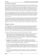
Page 14: ...n some installations when in scan mode To place the ITA2000A into monitor mode the desk set must force a channel steer to the desired channel by generating the appropriate function tone burst This causes the ITA2000A to stop scan and assert the PL DPL disable output to the radio placing the radio in monitor mode When in this mode the SCAN LED is lit Subsequent transmissions by the desk set will ca...

Page 15: ...usly selected channel or if in Scan mode returns to the previous scan state If scan were active prior to entering the home mode state the ITA2000A returns to scan upon exiting home mode state and generates a tone burst to the phone line to update the connected desk sets appropriately If scan were not active prior to entering home mode state the ITA2000A will not resume scan upon exiting home mode ...

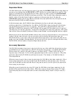
Page 16: ...entarily less than four seconds causes the ITA2000A to step up to the next test WARNING Disconnect the ITA2000A from the radio and disconnect all accessories from the ITA2000A when performing Diagnostic Tests 2 3 and 4 These diagnostics are used for factory testing only and perform input output configuration tests that may damage the interface to the radio and or any accessories connected to the I...

Page 17: ...pter can be installed in a customer supplied rack or cabinet or can be placed on a desk for convenience when used with microphones and other accessories A 19 inch standard rack panel 1 75 inches high is also available The GAI Tronics part number is XAC0005A Typical ITA2000A Installation ...

Page 18: ...a continuous and firmly fixed nonconductor such as porcelain tubes or flexible tubing in addition to the insulation on the wire Communications cables and in building wiring should be listed and marked for the purpose according to NEC Article 800 Optional cabling kits comply with these requirements and are recommended Telephone Line Lightning and Over voltage Protection The ITA2000A employs over cu...

Page 19: ...s dc power supply This supply must be capable of supplying the 0 3 A current required by the ITA2000A The ITA2000A operates properly on input voltages from 10 5 to 16 V dc The optional 40419 008 UL listed CSA certified Class 2 ac wall transformer should be used if a suitable dc source such as the station s dc supply is not available The power connection pinout is as follows Pins Function Pin 1 IN ...

Page 20: ...the scan rate and illuminates steadily when the adapter locks onto a channel monitor Locate SW1 7 on the unit s front panel and place it in the down position The unit will perform a reboot and begin operation in the Scan mode When the unit is powered up or when exiting diagnostics the hybrid balance tone will be heard twice This will not cause any harm to the system NOTE The scan or scanning featu...

Page 21: ... 2 O JU5 B position Lo 0 V dc JU5 A position Hi B J2 6 White PTT O JU2 B position Lo 0 V dc JU2 A position Hi B J2 7 Orange RX PL Disable O Closure between pins 7 and 14 J2 8 Red Channel Steer 0 O JU7 B position Lo 0 V dc JU7 A position Hi B J2 9 Red white Channel Steer 4 O JU3 B position Lo 0 V dc JU3 A position Hi B J2 10 Green white CSQ and CTCSS Detect SW1 1 must be Down Refer to Switch Table ...

Page 22: ... mode These pins are activated by a channel steer sequence until a PTT or scanning is resumed in Scan mode Connect to the radio receive PL DPL disable input so the radio will go into carrier squelch mode Since this connection is a closure one side of the closure can be connected to B or ground depending on the desired activation function logic If receive PL DPL disable is not supported by the radi...

Page 23: ...0 Hz High High Low High High F5 1550 Hz High High Low High Low F6 1450 Hz High High Low Low High F7 1350 Hz High High Low Low Low F8 1250 Hz High Low High High High F9 1150 Hz High Low High High Low F10 1050 Hz High Low High Low High F11 950 Hz High Low High Low Low F12 850 Hz High Low Low High High F13 750 Hz High Low Low High Low F14 650 Hz High Low Low Low High F15 550 Hz High Low Low Low Low F...

Page 24: ... V dc JU12 A position Hi B J3 6 White PTT I Lo 0 V dc J3 7 Orange RX PL Disable O Closure between pins 7 and 14 J3 8 Red Channel Steer 0 O JU14 B position Lo 0 V dc JU14 A position Hi B J3 9 Red white Channel Steer 4 O JU10 B position Lo 0 V dc JU10 A position Hi B J3 10 Green white CSQ and CTCSS Detect I SW1 2 UP Lo 0 V dc SW1 2 DOWN Hi B J3 11 Green black RX Audio O Connected internally to pin 4...

Page 25: ... Data input signal 1 13 14 Monitor low Orange w blk stripe 7 Earth Connected internally to 15D pin 4 at radio end of cable 15 Channel steer 1 Red w black stripe 3 Auxiliary input 2 programmable Connector Housing Shield Connected internally to 15D pin 4 at radio end of cable NOTES The Carrier Detect Signal COR must be programmed to an auxiliary output pin The Radio Connection Chart shows COR progra...

Page 26: ...RNING If programmable or N C pins are not used clip off or secure in a fashion to prevent leads from shorting together thus preventing damage to the adapter or the radio Adapter Radio Connector Connector Termination with Internal Jumpers Connecting Pins 4 11 14 ...

Page 27: ...8 9 12 or 14 Programmable 10 CTCSS IN Green w white stripe 4 8 12 or 14 Programmable 11 RX audio Connected internally to 15D pin 4 at radio end of cable 12 TX audio Blue 2 Mic audio 13 PTT Sense IN Blue w black stripe N C 14 Monitor low Connected internally to 15D pin 4 at radio end of cable 15 Channel steer 1 Red w black stripe 6 8 9 12 or 14 Programmable Connector Housing Shield Connected intern...

Page 28: ... Red N C Programmable 9 Channel Steer 4 Red w white stripe N C Programmable 10 CTCSS IN Green w white stripe 8 Programmable 11 RX audio Connected internally to 15D pin 4 at radio end of cable 12 TX audio Blue 23 Mic audio 13 14 Monitor low Connected internally to 15D pin 4 at radio end of cable 15 Channel Steer 1 Red w black stripe N C Programmable Connector Housing Shield Connected internally to ...

Page 29: ...e no signaling conversion by LEC IN Band 02NO4 4 wire private line no signaling conversion by LEC IN Band Metallic 2 or 4 wire metallic private line Hoot and Holler circuits Within a manufacturing plant campus or large building customer lines referred to as metallic pairs may be used To make appropriate phone line connections refer to the Telephone Line Connection Table below TelephoneLineConnecti...

Page 30: ...el Steer Output 1 JU7 B Channel Steer Output 0 JU8 B Accessory CSQ Output JU9 B Accessory PTT Output JU10 B Channel Steer Output 4 JU11 B Channel Steer Output 3 JU12 B Channel Steer Output 2 JU13 B Channel Steer Output 1 JU14 B Channel Steer Output 0 20 dB Out Reduces radio RX by 20 dB JU20 2W Select 2 wire 4 wire audio JU21 2W Select 2 wire 4 wire audio JU22 In Enables audio hybrid for 2 wire con...

Page 31: ...2 5 through SW2 8 ChannelRevertSettingsTable Switch Determines Up Down SW2 4 Whether channel selections are latched to last decoded frequency or revert to a preprogrammed channel SW2 5 to SW2 8 after transmit from land line Up Do not revert Down Revert based on SW2 5 to SW2 8 SW2 5 to SW2 8 The binary representation of the revert channel NOTE Revert channel must correspond to a BCD code 1 15 Rever...

Page 32: ...gh SW1 3 The active input level of radio PTT sense on radio connector pin 13 Active Low Active High SW1 4 Whether courtesy beep generation is enabled or disabled Disabled Enabled SW1 5 F16 Enable 2050 Hz is used for monitor 2050 Hz is used for F16 SW1 6 The polarity of monitor input from desk mic Active Low Active High SW1 7 Operate in Conventional or Scan mode Operate in Conventional mode Operate...

Page 33: ...put after a valid monitor command is detected Monitor output latched until a valid transmit command is detected from the wire line Monitor output is active 4 seconds after a valid monitor command is detected SW2 4 Whether channel selections are latched to last decoded frequency or revert to a preprogrammed channel SW2 5 to SW2 8 after transmit from wire line Stay on last decoded frequency from wir...

Page 34: ...vel of radio PTT sense on radio connector pin 13 Active Low Active High SW1 4 Whether courtesy beep generation is enabled or disabled Disabled Enabled SW1 5 How scan resumes after a desk set PTT The unit will cease scan and not resume after a desk set PTT The unit will resume scan after the scan stop time upon release of the desk set PTT SW1 6 The polarity of monitor input from desk mic Active Low...

Page 35: ... 15 SW2 5 to SW2 7 Scan Rate ms Time allotted for carrier detect per channel frequency Depending upon the radio and the programming of the radio used the time required for detection of valid carrier can vary Factors such as the design of the radio use of PL DPL and quieting can affect carrier detection time Consult your radio manual and manufacturer for specific carrier detect times NOTE The scan ...

Page 36: ...tor at 15 system deviation approximately 750 Hz of deviation 4 Adjust the RX level pot for 6 dBm 388 mV at U18 pin 7 or mic jack J4 pin 8 5 Remove the 1000 Hz tone or use diagnostic Test 1 LineOutputLevel The phone line level has been factory set to 0 dBm at reference input level This setting should be adequate for most installations Use the following procedure if readjustment is ever required NOT...

Page 37: ...e the remote is in the transmit mode When working alone another option is to carry a spare tone remote desk set to the base site Connect it to the adapter s phone line connector and use it to perform this test The remote s transmit level must be within the automatic gain control range of the adapter which is 24 dBm to 0 dBm Monitor the station with the modulation monitor set to the station s opera...

Page 38: ...ay damage the interface to the radio and or any accessories connected to the ITA2000A Test 1 Test 1 can be used to set up system audio levels It routes a 1000 Hz reference tone to the telephone line and the transmit audio of the radio connector 1 Adjust the transmit audio pot to the desired level of system deviation 2 To set the ITA2000A receive audio sensitivity level from the radio inject a 1000...

Page 39: ... Audio from the phone line enters the unit at J1 3 and J1 4 and passes through transformer T2 and then buffered by amplifier U24c The output of U24c is fed into digital pot U22 the DSP U1 adjusts U22 for an output internal reference level of 6 dB The reference level is input at pin 14 of codec U21 The digital output of U21 is fed to U1 DSP The digital signal is then converted back to analog and ou...

Page 40: ...ic PTT input and routed to radio TX output telephone line output and the accessory RX output For radio TX the audio is routed to amplifier U16 then output to the radio TX For telephone line output the audio is routed to amplifier U23 then output to the telephone line connection For accessory RX output the audio is routed to amplifier U27 then output to the accessory RX output ResetCircuit An inter...

Page 41: ...ents information starting on page 32 in the Installation section of this manual Ensure that the telephone line is balanced by making sure neither side of the telephone line is grounded Ensure that there is no more than 20 dB of loss in the telephone line There is squelch noise in RX audio or no RX audio Ensure that the telephone line is balanced by making sure neither side of the telephone line is...

Page 42: ...s configured for resume scan after PTT ensure that PTT is generated by the remote Ensure that there is no off hook mic or shorting plug connected to the mic port of the ITA2000A and that the monitor pin of the accessory connector is not asserted ITA2000A does not transmit or receive Ensure that there is a telephone line audio path from the ITA2000A to the tone remote desk set Check that neither fu...

Page 43: ...39 03 13 Main Circuit Board ...

Page 44: ...Main Circuit Board ITA2000A Series Tone Remote Adapter 40 ...

Page 45: ...41 03 13 Schematics ...

Page 46: ...Schematics ITA2000A Series Tone Remote Adapter 42 Digital Section Schematic Diagram Sheet 1 of 6 ...

Page 47: ...ITA2000A Series Tone Remote Adapter Schematics 43 Serial Logic Schematic Diagram Sheet 2 of 6 ...

Page 48: ...Schematics ITA2000A Series Tone Remote Adapter 44 Power Supply Section Schematic Diagram Sheet 3 of 6 ...

Page 49: ...ITA2000A Series Tone Remote Adapter Schematics 45 Line Interface Schematic Diagram Sheet 4 of 6 ...

Page 50: ...Schematics ITA2000A Series Tone Remote Adapter 46 Radio Phone and Mic Schematic Diagram Sheet 5 of 6 ...

Page 51: ...ITA2000A Series Tone Remote Adapter Schematics 47 Output Port Schematic Diagram Sheet 6 of 6 ...

Page 52: ...Schematics ITA2000A Series Tone Remote Adapter 48 Notes ...

Page 53: ... steers not asserted and scan stopped LLGT Low level guard tone Monitor Mode PL DPL disable DPL A system analogous to PL but using low speed digital signaling instead of subaudible tones PL A means of grouping users of a common radio channel Subaudible tones are transmitted with audio a particular radio s speaker or the speakers of a group of radios will unmute to broadcast a transmission only if ...

Page 54: ...Notes ITA2000A Series Tone Remote Adapter 50 ...

Reviews: