background image

2500 - 3069

1 (888) 425-2262

2500 - 3069

ELECTRICAL

Summary of Contents for MOVFE 2500

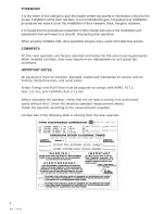
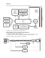
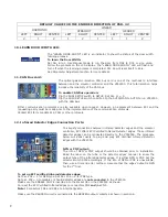
Page 1: ...2500 3069 1 888 425 2262 2500 3069 ELECTRICAL...

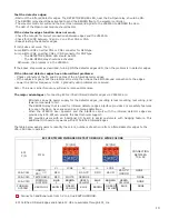
Page 2: ...Rev 1 10 20 I...

Page 3: ...N bus module 9 12 Infrared Detector Edges Connection Ports 9 13 Parameter Unit 11 INITIAL SETUP 14 1 Turn Power ON 14 2 Motor Direction 14 3 Encoder Direction 14 5 Learn The door width 16 5 1 Door is...

Page 4: ...e 28 CD Opening Time 28 DCL DOL Time 28 LED Indicators 28 SPEED PROFILES OF THE VFE2500 29 Normal Door 29 Heavy Door 30 Narrow Door 31 SENSORS SETTING 32 Hall effect sensors setting for linear door op...

Page 5: ...IME SETUP 64 MINIMUM CLOSING TIME ECI REFERENTIAL VALUE 65 CHECKING PROCEDURE FOR THE CLOSING CODE TIMES 66 INTERFACING BETWEEN ECI CERTIFIED LIGHT CURTAIN AND VFE2500 67 Understanding the RE OPEN rel...

Page 6: ...rol diagram of the VFE2500 TERMINAL INPUTS CAN BUS KEYPAD OR RS 485 VFE2500 DRIVE QUADRATURE ENCODER INFRARED DETECTOR EDGES OPTIONAL TRANSMITTER RECEIVER 3PH INDUCTION MOTOR 230VAC POWER SUPPLY OPTIC...

Page 7: ...udging heavier narrower input signals Door open and close directions Open and close slowdown Obstruction detection signal Stall reverse Frequency failure DOL DCL AUX Narrower door and DPM Door Protect...

Page 8: ...prevent run away conditions that could otherwise result in a closed loop control system This combination of hardware and software provides an ultimate protection for human life SERIAL COMMUNICATION TO...

Page 9: ...ely 4 NUDG Nudging NUDG switch allows closing the door at a reduced speed Nudging speed To test the Nudging speed in Manual mode the AUTO MAN switch must be in the MAN position and the CLOSE OPEN and...

Page 10: ...Heavier and Narrower door functions Note that if the input signals voltage is 60V or less the jumpers on each input module must be removed There are 20 more LEDs on the main board to indicate the com...

Page 11: ...s transfer board and arranged as follows Number on Figure Label Remarks 1 DOL Door Open Limit The VFE2500 utilizes the DOL limit signal for door width learning After the door width learning process is...

Page 12: ...DPM is designed to work with the Fault Monitor FM FM is a patented door lock and gate switch protection device Its purpose is to meet the ASME A17 1 RULE 210 15 and CAN CSA B44 M90 RULE 3 12 1 5 The s...

Page 13: ...Par 68 the AUX2 relay will be activated Buzzer once the infrared detector edge is obstructed and after a delay set by Par 198 the output of the Buzzer will be activated Buzzer operation is controlled...

Page 14: ...party must be made prior to the implementation of the communication protocols Contact ECI for more details in CAN or other protocols To simplify connections between infrared detector edges and the el...

Page 15: ...til problems are resolved Note The lower carrier frequency will create more audible noise The major advantages of connecting ECI certified infrared detector edges via VFE2500 are Eliminates an extra p...

Page 16: ...rth ground Note A True Earth Ground is required Convenience Gate switch terminals GS GS1 Note GS GS1 are only convenience terminals They have no internal connection to the VFE2500 3 phase induction mo...

Page 17: ...is used for Light Duty Linear model Three models of VFE2500 system are available VFE2500 HH Heavy Duty Harmonic model VFE2500 GL Light Duty Linear model VFE2500 HL Heavy Duty Linear model Left hand ri...

Page 18: ...13 MOVFE2500 Heavy Duty Harmonic Model MOVFE2500 Light Duty Linear Model i d l Parameter Unit not included if required part 2500 3051 Parameter Unit not included if required part 2500 3051 13...

Page 19: ...tup pr dure is help is to assure the correc in the corr ault param is learned source is se Run the d o 3 Otherw n On the P on the dis Or on the dis 42 from 1 rior to shipp pful for use e the follow ct...

Page 20: ...15 4 Download an GAL default parameter set Follow steps of the illustration below to download write a correct default parameter set to the 02VFE2500 drive then go to 6 15...

Page 21: ...completed ack to Zero e cases tween DOL OSE OPEN sw ly OPENED ly CLOSED WRITE P rom DOL to play LEARN L and DCL b witch is pre D DOL is rea DCL is rea E DCL or vic DOOR WID before learn ssed in the ac...

Page 22: ...le switch to SETUP Set par 11 1 for Terminals operation Set par 11 5 for CAN bus operation Flip the 1st toggle switch to RUN Flip the 2nd switch to MAN to run the door in manual mode Flip the 2nd swit...

Page 23: ...ip the RUN SETUP switch to RUN Use Manual mode to run the door from DOL to DCL or vice versa Follow the prompts on the LCD display LEARN DOOR WIDTH LED will flash and turn off when the learning proces...

Page 24: ...19 6 DEFAULT PARAMETERS 19...

Page 25: ...ers navigate through the Parameter Unit seamlessly Press then press or to navigate all items under the VIEW section Once the desired item is found press to view an item Press at any time to get back t...

Page 26: ...21 FAULTS AN EXAMPLE OF FAULTS DISPLAY COUNTERS 21...

Page 27: ...22 USER LIST 22...

Page 28: ...23 23...

Page 29: ...24 24...

Page 30: ...25 25...

Page 31: ...26 MAXIMUM CLOSE SPEED AND FORCE 26...

Page 32: ...27 ECI DEFAULT PARAMETER SETS 27...

Page 33: ...CLOSING TIME DISPLAY CAN ANALYZER AN EXAMPLE 9 LED INDICATORS There are 7 LEDs on the Parameter Unit DO DC NUD HLD PRG FLT and OVT They have the following meanings DO Door Open DC Door Close NUDG Nud...

Page 34: ...29 SPEED PROFILES OF THE VFE2500 FOR NORMAL DOOR 29...

Page 35: ...30 SPEED PROFILES OF THE MOVFE2500 FOR HEAVY DOOR 30...

Page 36: ...31 SPEED PROFILES OF THE MOVFE2500 FOR NARROW DOOR 31...

Page 37: ...l settings of the hall effect sensors as reference for optical sensors Last Inch Inch before Gate Switch makes Magnet Magnet Carrier Use as DOL of the Narrower door Also can be used as a 2nd DOL When...

Page 38: ...ted Volt 400 00 50 00 Hz 60 Max Speed 28 MIN Output Voltage 25 0 0 0 4 0 Min Voltage Higher than Par 126 185 29 Min Output Freq 400 00 0 10 Hz 0 50 Min Output Spd Lower than Par 127 186 31 Motor Rated...

Page 39: ...S O 1 Harmonic C P 2 Linear Straight S O 3 Linear Straight C P 4 Linear Gear S O 5 Linear Gear C P Door Type GROUP 2 DOOR PARAMETERS Par No Description Range Unit Default Setting Display Related Par...

Page 40: ...A Linear Geared S O Open HLD Torque 80 Open Holding Speed 0 00 400 00 Hz 2Hz Open HLD Spd 81 Open Holding Start 0 0 100 99 Holding Start 82 Slow Speed Open 0 00 400 00 Hz 5Hz Harmonic C P 5Hz Harmonic...

Page 41: ...ear Straight C P 12sec Linear Straight S O 12sec Linear Geared C P 4sec Linear Geared S O Open Dec TM 89 Open Torque 0 00 400 00 Hz 120Hz Harmonic C P 120z Harmonic S O 80Hz Linear Straight C P 80Hz L...

Page 42: ...red S O Hvy Spd HSO 99 Heavy Final Speed Open 0 00 400 00 Hz 7Hz Harmonic C P 7Hz Harmonic S O 3Hz Linear Straight C P 5Hz Linear Straight S O 3Hz Linear Geared C P 5Hz Linear Geared S O Hvy Spd FSO 1...

Page 43: ...Straight C P 2 0A Linear Straight S O 1 2A Linear Geared C P 1 2A Linear Geared S O Nar Quick Rev 107 Narrow Holding Torque 0 0 3 0 A 0 6A Harmonic C P 0 6A Harmonic S O 0 6A Linear Straight C P 0 6A...

Page 44: ...tion Time 0 1 3600 0 sec 6sec Harmonic C P 4sec Harmonic S O 6sec Linear Straight C P 4sec Linear Straight S O 4sec Linear Geared C P 2sec Linear Geared S O Nar Open Acc TM 116 Narrow Open Deceleratio...

Page 45: ...rq LPF 127 Open Timeout 0 0 180 0 sec 0 0sec Open Timeout 128 Open Lock Torque 1 0 0 4 5 A 0 0A Open Lock Torq1 129 Open Lock Torque 2 0 0 4 5 A 0 0A Open Lock Torq2 130 Open Holding Time 0 0 999 9 se...

Page 46: ...inear Geared S O Holding Start 140 Close Torque 0 00 400 00 Hz 243Hz Harmonic C P 173Hz Harmonic S O 270Hz Linear Straight C P 270Hz Linear Straight S O 100Hz Linear Geared C P 120Hz Linear Geared S O...

Page 47: ...1 3600 0 sec 8sec Harmonic C P 10sec Harmonic S O 15sec Linear Straight C P 20sec Linear Straight S O 10sec Linear Geared C P 4sec Linear Geared S O Close Dec TM 148 Stall Reverse Force 0 0 4 5 A 1 6...

Page 48: ...ight S O 12Hz Linear Geared C P 10Hz Linear Geared S O Hvy High HSC 157 Heavy Final Speed Close FSC 0 00 400 00 Hz 5Hz Harmonic C P 5Hz Harmonic S O 3Hz Linear Straight C P 2Hz Linear Straight S O 4Hz...

Page 49: ...0 0 100 0 4 Hvy Close Mid V 166 Heavy Close Mid Frequency 0 00 400 00 Hz 0 5Hz Hvy Close Mid F 167 Narrow Close Holding Torque 0 0 4 5 A 0 6A Harmonic C P 0 6A Harmonic S O 0 6A Linear Straight C P 0...

Page 50: ...P 10 Linear Geared S O Nar FSC Start 174 Narrow Nudging Speed 0 00 400 00 Hz 15Hz Harmonic C P 9Hz Harmonic S O 10Hz Linear Straight C P 15Hz Linear Straight S O 15Hz Linear Geared C P 15Hz Linear Gea...

Page 51: ...lose Holding Time 0 0 999 9 sec 0 0sec CLOSE Hold Time 190 Close Acceleration S curve 0 0 10 0 sec 0 5sec Close Acc Scurve GROUP 5 DIGITAL I O PARAMETERS Par No Description Range Unit Default Setting...

Page 52: ...Holding Time for Edges Timeout relay 0 0 180 0 sec 3sec Default EdgesTimeout HLD 207 Reopen Relay Mode 1 0 0 MAINTAIN 1 DISABLE WHEN EDGES RELAY ON Reopen Relay MOD 219 Nudging Torque 0 400 A 173 Nud...

Page 53: ...ormat 243 RS485 Connection Loss 0 3 0 Warn and keep operating 1 Warn and ramp to stop 2 Warn and coast to stop 3 No warning and keep operating Default Comm Loss Action 244 RS485 Connection Loss Time 0...

Page 54: ...N 87654321 D8 Digital Input Status Bit0 CLOSE Bit1 OPEN Bit2 NUDG Bit3 NARROW Bit4 HEAVY Bit5 IR Bit6 SPARE 1 Bit7 SPARE 2 MI IN 87654321 D9 Sensor Input Status Bit0 HALL DOL Bit1 HALL AUX Bit2 HALL D...

Page 55: ...D17 Drive Type Drive Type D18 Warning Code Warn Code D19 Memory Probe Display Testpoint Data D20 NMI state NMI State D21 Door Code Time Reg Code Time sec D22 Door Code Time for Nudging Nudg Code Time...

Page 56: ...C CONTACT OPENS WHEN DOOR REACHES FINAL CLOSE LIMIT DCL RELAY IS CONTROLLED BY DCL CAM FOR HARMONIC MODEL OR BY DCL HALL EFFECT SENSOR FOR LINEAR MODEL SEE NOTE 1 4 AMP SLOW BLOW FUSES CODE DIST NARR...

Page 57: ...OPENS WHEN DOOR REACHES FINAL CLOSE LIMIT DCL RELAY IS CONTROLLED BY DCL CAM FOR HARMONIC MODEL OR BY DCL HALL EFFECT SENSOR FOR LINEAR MODEL SEE NOTE 1 8 AMP SLOW BLOW FUSES CODE DIST NARROW DOORWID...

Page 58: ...Vbase Par 90 OPEN Vmid Par 29 Fmin Par 91 OPEN Fmid Par 151 CLOSE Par 150 CLOSE Par 28 Vmin Par 89 OPEN Par 140 CLOSE Fbase Fmax Par 27 OUTPUT VOLTAGE V OUTPUT FREQUENCY Hz V F GRAPH FOR HEAVY DOOR Pa...

Page 59: ...PEN Vmid Par 29 Fmin Par 119 OPEN Fmid Par 181 CLOSE Par 180 CLOSE Par 28 Vmin Par 117 OPEN Par 170 CLOSE Fbase Fmax Par 27 OUTPUT FREQUENCY TIME DC OUTPUT CURRENT FREQUENCY DETECTION DURATION AND INT...

Page 60: ...UENCY FAILURE DETECTION RE OPEN RELAY OFF OFF ON FREQUENCY FAILURE DETECTION Par 136 TIME INFRARED DETECTOR EDGES DETECTION LCSE FROM INFRARED DETECTOR EDGES DEACTIVATE ACTIVATE DEACTIVATE RE OPEN REL...

Page 61: ...LAY OFF OFF ON EDGES DELAY Par 197 EDGES HOLD TIME Par 206 BUZZER OFF OFF ON BUZZER DELAY Par 198 EDGES TIMEOUT RELAY AND BUZZER MODE LCSE FROM INFRARED DETECTOR EDGES DEACTIVATE ACTIVATE DEACTIVATE E...

Page 62: ...AND EDGES TIMEOUT RELAY REOPEN RELAY EDGES TIMEOUT RELAY LCSE FROM INFRARED DETECTOR EDGES DEACTIVATE ACTIVATE DEACTIVATE EDGES TIMEOUT RELAY OFF OFF ON EDGES DELAY Par 197 EDGES HOLD TIME Par 206 RE...

Page 63: ...range 2 Check for possible voltage transients 3 DC bus over voltage may also be caused by motor regeneration 4 Increase the deceleration time 5 Check whether the required braking power is within the...

Page 64: ...uit at motor output Check for possible poor insulation at the output line 2 Deceleration Time too short Increase the Deceleration Time Fault Display Meaning Reset Auto Reset Record Drive Response Rese...

Page 65: ...Immediately Remedy 1 Check the RS485 connection between the AC motor drive and RS485 master for loose wires and wiring to correct pins 2 Check if the communication protocol address transmission speed...

Page 66: ...Drive Response Reset Condition DPM Sensor Fail DPM Error Yes Yes Yes Warning Scan Speed Recover if the signal is detected appropriately Remedy 1 Check the DPM sensor 2 Check the wirings of DPM sensor...

Page 67: ...ION IS REMOVED Yes No WAITING FOR FAULT CONDITION TO BE REMOVED PAR 222 NEW PAR 222 OLD 1 FAULT RESET NORMAL OPERATION START RESET TIMER RESET TIMER PAR 226 STOP THE DRIVE Yes No PAR 222 NEW PAR 222 O...

Page 68: ...nd prevent fuses from blowing VOLT PULSE CLUTCH REAR VANE BY 1 8 PAST 1 2 APPROX BUMPER BUMPER REMOVED CAR DOORS 1 2 OPEN HATCH DOOR DOOR IS FULLY CLOSED AND CAR DOORS THE ROLLER AS SHOWN WHEN HATCH I...

Page 69: ...rther moving Stop the door anywhere from one third to two thirds of the door travel Press the spring gauge against the door remove the stop Hold the spring gauge until the door stands still and take t...

Page 70: ...2 minus Count1 of the Count into Par 69 Do the same procedure and enter the difference of the count into Par 70 for the Narrower door if used The display of the Code Distance Closing Time is in the su...

Page 71: ...PAR 52 READ ONLY 0 HARMONIC S O 1 HARMONIC C P 2 LINEAR STRAIGHT S O 3 LINEAR STRAIGHT C P 4 LINEAR GEARED S O 5 LINEAR GEARED C P ENTER DOOR WIDTH INCHES PAR 49 ENTER DOOR S WEIGHT LBS PAR 50 ENTER...

Page 72: ...AND CHECK AGAIN REGULAR CLOSING OR NUDGING SPEED REGULAR SPEED NUDGING SPEED DECREASE HSC PAR 141 AND CHECK AGAIN DECREASE HEAVY HSC PAR 156 AND CHECK AGAIN HEAVIER DOOR OR NORMAL DOOR NORMAL DOOR HE...

Page 73: ...ill be Certified T CURTAIN AN wing detection lled by Par 2 rd features of to the VFE25 mers eliminat ntly in case o with the matc nsure a seam tor edges ma rs CN5 CN5 and VFE2500 5 n 1 2 Rea detect NP...

Page 74: ...RSION BROWN GREEN YELLOW BLUE BROWN GREEN YELLOW BLUE NONE Connect an additional wire from 0V to a true EARTH GROUND Check for 24VDC between 0V and V on either CN4 CN5 Test the Infrared Detector Edges...

Page 75: ...ection INFRARED DETECTOR EDGES RE To E E OPEN Signa levator Contr Ele sign al roller vator Contro nal to the VFE In REO ller sends Do E2500 to RE O nfrared Edges OPEN relay IN or Open com OPEN the doo...

Page 76: ...S IS UNOBTAINABLE SET SW8 TO EITHER NPN OR PNP OTHERWISE SET THE SW8 APPROPRIATELY OBSTRUCT THE EDGES Yes No MAKING SURE THAT PAR 197 PAR 206 HAVE NON ZERO VALUES PAR 207 0 FOR THE FOLLOWING PROCEDURE...

Page 77: ...nt of ve this issue eavier door t of paramete which accep mper of the i urrent from th ntroller has s rs are Par 9 wo different h ne door may Kinetic energ When the HE ers users nee pts the contr nput...

Page 78: ...of the in current from t up to indicat sed when Par the completio UX NARROWE an be either t ters are Par dicator for ROWER Relay wo different h e Mechanical code violation ue When the wer door meters...

Page 79: ...T DETECT AUX SENSOR DOES AUX SENSOR FAIL Yes No AUX OUT AUX IN AUX OUT PAR 65 AUX IN Yes No AUX OUT 1 DOOR COUNT PAR 65 Yes No Yes PAR 204 0 Yes USE BOTH AUX AND DOL RELAYS NARROW DOOR INPUT DOL 1 Yes...

Page 80: ...M output sig Elevator Con for NUDG Applicat INFRARED DETECTOR EDGES o order an Ad E OUT relay a he mechanism Fire Service C ll remain egardless Infrared Time EDGES T MEOUT nal to ntroller GING tion dd...

Page 81: ...RELAY EDGES TIME OUT DELAY TIMER PAR 197 EXPIRED Yes TURN ON EDGES TIMEOUT OUTPUT RELAY LED INFRARED DETECTOR EDGES ARE UNOBSTRUCTED Yes No SETTING OF EDGES TIMEOUT HOLD TIMER PAR 206 0 Yes TURN OFF E...

Page 82: ...meter u g Modbus p rotocols are e made pr d other pro I31 28 I27 2 D3H D3L I31 28 I27 2 D3H D3L municate be s Otherwis et Par 246 flipping the it for CAN 247 is 11 frame on t ts for Data unit can als...

Page 83: ...on VFE2500 close Signal transfe model Optical cam b ts can be pur s the right to e looped r board for oard chased from replace any i Picture ECI items in this list at any tim me without no otice ECI P...

Page 84: ...utputs conne nector 3 posi etector edges ector 3 posit the hall effect ector 9 posit or output sign additional I O board connector ition inputs ctor ition infrared connector ion connecto t sensor PCB...

Page 85: ...narrow able IC 24VDC coil v p 250VAC re le Galvanic is der module le Galvanic Is odule le Universal der for HP A connector for w door input voltage elay solation solation can input module AC motor r...

Page 86: ...Edges edges Edges detect Edges Janus infrare Tritronics in tor edges Formula Sys detector e ed detector frared stems infrare edges d 906 3013 906 3020 906 3030 80 0 80...

Page 87: ...10 pin ribb he signal trans e 7 ft Cable fo Unit Cable 7 in Parameter 4 Amp Slow B r 3 Phase 230 tion Motor on cable for board bon cable for sfer board or Parameter Cable for r Unit Blow fuse 0VAC 1...

Page 88: ...r 91W 3 phas ed Motor Le r 91W 3 phas ed Motor Rig former 500V Plastic Cam meter Unit orce Gauge S all force meas se 230VAC eft hand se 230VAC ght hand VA 110 220 Spring gauge surement 2500 2016 L 250...

Page 89: ...Manu VFE25 Quick Bracke al Hard copy 500 electrical setup brochu et Hall effect y of the manual ure t sensor 2500 3069 2500 3066 2500 5019 83 3 83...

Page 90: ...Cover VFE25 Plastic cove 500 drive r for the 2500 3052 84 4 Cover VFE25 Plastic cove 500 drive r for the 2500 3052 1 84...

Page 91: ...Rev 10 20 85...

Page 92: ......

Reviews: