3Ennnn Gallagher T30 Reader Installation Note| DRAFT2 | July 2020
Copyright © Gallagher Group Limited
Page 1
Gallagher
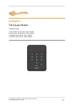
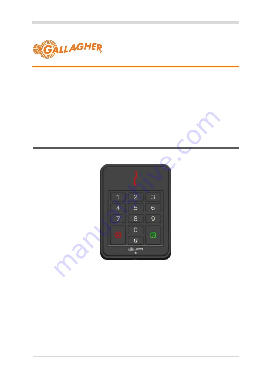
T30 Keypad Reader
Installation Note
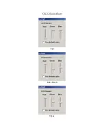
T30 MULTITECH® Keypad Reader, Black: C300490
T30 MULTITECH® Keypad Reader, White: C300491
T30 MIFARE® Keypad Reader, Black: C300495
T30 MIFARE® Keypad Reader, White: C300496