
Mounting and Operating Instructions for
Powered Auxiliary Outboard Motor
Brackets Models 71095 and 71096
Form 12.441
Thank you for choosing the Garelick/EEz-In Brand. The
design/technology found in features of this product represent
over 25 years of auxiliary outboard motor bracket experience
and the fourth generation of brackets offered by our company
to the boating public.
We are proud to manufacture this product to help you enjoy
your time on the water. If you would like to comment on your
experiences, please feel free to contact us by e-mail or write a
letter to our Customer Service Center. When contacting us,
please provide the serial number, which gives us the date of
manufacture.
FIG. 1
Write for
a Complete
Catalog
Phone: 651-459-9795
PO Box 8, 644 2nd Street
E-mail: mail@garelick.com
St. Paul Park, Minnesota 55071
On the Web: www.garelick.com
10/01
SUPPLIED HARDWARE:
Part No.
Quantity
Description
49.274
0
1 each
electrical harness with operating switch
03.412
4 each
1/2–20 x 4-1/2” stainless steel bolts
03.413
4 each
1/2” x 1-1/2” stainless steel washers
03.414
4 each
1/2” x 7/8” stainless steel washers
03.411
4 each
1/2–20 brass locknuts
MOUNTING INSTRUCTIONS
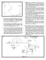
Note:
The approximate vertical travel of the 71095/71096 Motor
Brackets is 13”. This travel is based on installation that’s
perpendicular to the water surface. The vertical travel will be less
than 13” if the installation is on a positive angled transom, and will
be more than 13” if installed on a negative angled transom. If your
transom angle is more than 10° out of perpendicular, we
recommend fabricating a wedged spacer out of a suitable material
such as starboard, aluminum or finished hardwood to allow your
installation to be perpendicular to the water surface.
Failure to
follow these instructions can cause the actuator to retract below
a horizontal position. This may cause the pump to draw air and
fail to return to a stowed position.
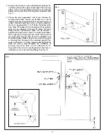
The outside dimensions should
be a minimum of 5-1/2" x 11-1/2", one for each mounting angle,
or a single piece 11-1/2" x 20-1/2".
1. The Motor Bracket is shipped in the mid-stroke position. To
complete installation, it is necessary to activate the Bracket
to full down position. Set the Bracket on a flat surface. With
a standard 12 volt battery, connect the green cable to the
positive terminal and the blue cable to the negative
terminal. This will cause the hydraulic cylinder to retract to
SPECIFICATIONS
H.P. Rating
Motor Weight
Vertical
Mounting
Mounting Board
Mounting Bracket
Not to Exceed
Travel
Pad
Dimensions
Dimensions
W x H x T
W x H
71095
Up to 25
148 lbs.
13-1/4”
poly/alum
15-3/4” x 14” x 2”
12-1/4” x 8”
(33 cm)
(40 x 35 x 5 cm)
(31 x 20 cm)
71096
25 to 40
248 lbs.
13-1/4”
poly/alum
15-3/4” x 14” x 2”
16-1/4” x 8”
(33 cm)
(40 x 35 x 5 cm)
(41 x 20 cm)
Triple coat protective finish (anodized, E-Coat, powder coated).
1
its shortest length or closed position. This is the full down
position for the motor bracket. Disconnect the negative
cable followed by the positive cable. (See Figures 1 and 2)
(continued)


