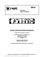
background image

190-00303-21 

January, 2010 

Revision C


(GMA 1347D -00 Shown) 


GMA 1347D
Installation Manual


Summary of Contents for 011-01257-00

Page 1: ...190 00303 21 January 2010 Revision C GMA 1347D 00 Shown GMA 1347D Installation Manual ...

Page 2: ...s manual or of any revision hereto provided that such electronic or printed copy of this manual or revision must contain the complete text of this copyright notice and provided further that any unauthorized commercial distribution of this manual or any revision hereto is strictly prohibited Garmin International Inc 1200 E 151st Street Olathe KS 66062 USA Telephone 913 397 8200 Aviation Dealer Tech...

Page 3: ...KR TEL AUX to Equipment Description 1 2 1 2 2 Added to Interface Summary 1 7 1 6 Updated warranty statement 2 1 2 1 2 2 2 Updated AC reference C 2 2 2 3 2 3 1 Added marker beacon installation guidance DOCUMENT PAGINATION Section Page Range Table of Contents i vi Section 1 1 1 1 8 Section 2 2 1 2 6 Section 3 3 1 3 4 Section 4 4 1 4 12 Appendix A A 1 A 6 Appendix B B 1 B 12 ...

Page 4: ...leased or disclosed to foreign nationals inside or outside of the United States without first obtaining an export license A violation of the EAR may be subject to a penalty of up to 10 years imprisonment and a fine of up to US 1 000 000 under Section 2410 of the Export Administration Act of 1979 Include this notice with any reproduced portion of this document WARNING This product its packaging and...

Page 5: ...g 2 4 2 5 Cooling Air 2 4 2 6 Mounting Requirements 2 5 2 7 Installation Approval Considerations for Pressurized Aircraft 2 6 2 8 Electrical Noise 2 6 3 INSTALLATION PROCEDURE 3 1 3 1 Unpacking Unit 3 1 3 2 Antenna Installation 3 1 3 3 Antenna Cable Connectors 3 1 3 4 Electrical Connections 3 1 3 5 Backshell Assembly 3 2 3 6 GMA 1347D Unit Installation 3 3 3 7 Post Installation Configuration and C...

Page 6: ...1 GMA 1347D Outline Drawing A 1 A 2 GMA 1347D Connector Rack Assembly Drawing A 3 A 3 GMA 1347D Recommended Panel Cutout Dimensions A 5 B 1 GMA 1347D Power Antenna and Reversionary Mode Interconnect Wiring Diagram B 1 B 2 GMA 1347D Power Antenna and Reversionary Mode Interconnect Wiring Diagram B 3 B 3 Mic and Phone Jack Connections Interconnect Wiring Diagram B 5 B 4 Transceiver Analog Connection...

Page 7: ...aker Pin Assignments J3472 4 8 4 9 Digital Audio Pin Assignments J3472 4 8 4 10 PA MUTE Pin Assignments J3472 4 8 4 11 Mic Audio Inputs and Mic Key Pin Assignments J3471 4 9 4 12 Remote ICS Audio and ICS Keys Pin Assignments J3471 4 9 4 13 Com Audio and Mic Keys Pin Assignments J3471 4 10 4 14 Nav Audio Pin Assignments J3471 4 10 4 15 Headset Outputs Pin Assignments J3471 4 11 4 16 Music Inputs Pi...

Page 8: ...date and the purpose of the modification The table is current at the time of publication of this manual see date on front cover and is subject to change without notice Authorized Garmin Sales and Service Centers are encouraged to access the most up to date bulletin and advisory information on the Garmin Dealer Resource web site at www garmin com using their Garmin provided user name and password M...

Page 9: ...GMA 1347D Audio Panel incorporates a microcontroller for processing front panel key commands annunciator control input output functions and communication The GMA 1347D includes a five position intercom system ICS with electronic cabin noise de emphasis and two stereo music inputs A dual installation extends the number of ICS positions to ten The intercom provides two selectable modes of isolation ...

Page 10: ...ff fail safe connection for Pilot PTT mic and Pilot s Headset Left to ON SIDE COM Digital audio interface Voice Recorder Cockpit Call 20 only 1 2 2 Interface Summary The following is an interface summary for the GMA 1347D See Section 4 and Appendix B for connection details 3 Transceiver Inputs Outputs Figure B 4 1 Speaker Output Figures B 1 and B 2 2 Headset Outputs Figure B 3 5 Microphone Inputs ...

Page 11: ... Garmin part number 005 00314 79 To obtain a copy of this form see the dealer OEM portion of the Garmin web site www garmin com 1 3 1 Physical Characteristics Characteristic Specification Bezel Height 7 70 inches 196 mm Bezel Width 1 30 inches 33 mm Rack Height 6 30 inches 160 mm Rack Width 1 325 inches 34 mm Depth Behind Panel with Connectors measured from face of aircraft panel to rear of connec...

Page 12: ... for full output typical 1 Vac RMS MAX 3 Vp p Microphone signal processing 9 pole characteristic and special cabin noise band de emphasis Intercom isolation modes 00 2 Pilot Isolate Crew Isolate Intercom isolation modes 20 4 Pilot Isolate Crew Isolate Copilot Isolate All ICS Mode Special functions Recorder with playback selectable recording of selected COMs up to 2 5 minutes of recording time Auto...

Page 13: ...03 39 006 C0051 20 006 C0075 00 006 C0075 01 006 C0075 03 006 C0090 006 C0091 006 C0090 006 C0091 Airborne Radio Marker Receiving Equipment TSO C35d ETSO 2C35d Class A All 006 B0203 except 006 B0203 00 through 006 B0203 29 All 006 B0203 except 006 B0203 00 through 006 B0203 39 006 C0051 20 006 C0075 00 006 C0075 01 006 C0075 03 006 C0090 006 C0091 006 C0090 006 C0091 Not RTCA DO 254 Level C Compli...

Page 14: ...lications are sources of additional information for installing the GMA 1347D Before installing the unit the technician should read all referenced materials along with this manual Part Number Document 190 00303 00 G1000 System Installation Manual 190 00303 04 G1000 Line Maintenance and Configuration Manual ...

Page 15: ...F MERCHANTABILITY OR FITNESS FOR A PARTICULAR PURPOSE STATUTORY OR OTHERWISE THIS WARRANTY GIVES YOU SPECIFIC LEGAL RIGHTS WHICH MAY VARY FROM STATE TO STATE IN NO EVENT SHALL GARMIN BE LIABLE FOR ANY INCIDENTAL SPECIAL INDIRECT OR CONSEQUENTIAL DAMAGES WHETHER RESULTING FROM THE USE MISUSE OR INABILITY TO USE THE PRODUCT OR FROM DEFECTS IN THE PRODUCT SOME STATES DO NOT ALLOW THE EXCLUSION OF INC...

Page 16: ...Page 1 8 GMA 1347D Installation Manual Revision C 190 00303 21 This page intentionally left blank ...

Page 17: ...it Only 011 01257 00 010 00465 00 GMA 1347D Cabin Unit Only 011 01257 20 010 00465 20 2 2 1 Equipment Available Each of the following accessories are provided separately for the GMA 1347D Item Garmin P N Sub Assy Connector Kit SB GMA 1347 011 00813 01 SMP Install Rack GMA 1347 115 00427 00 Sub Assy Bracket Kit GMA 1347 011 01001 00 Sub Assy Backplate GMA 1347 011 00812 00 Sub Assy Nut Plate Kit GM...

Page 18: ...away as possible from transmitter antennas 2 3 1 2 Marker Beacon Antenna Mounting Install the antenna according to the antenna manufacturer s instructions If the antenna is being installed on a composite aircraft ground planes must sometimes be added Conductive wire mesh radials or thin aluminum sheets embedded in the composite material provide the proper ground plane allowing the antenna pattern ...

Page 19: ...shield to D Sub as short as possible Ensure the distance from the beginning of the exposed shield to D Sub is no more than 1 5 inches long Terminate the center conductor by directly connecting it to the D sub through a crimp pin without a pigtail Figure 2 1 below represents a suggested method for terminating the marker beacon coaxial cable using M17 128 RG400 terminated into a 78 Pin high density ...

Page 20: ...arrels inside the backshell If using 16 or 18 barrel contacts ensure that no two contacts are mounted directly adjacent to each other This minimizes the risk of contacts touching and shorting to adjacent pins and to ground Ensure that routing of the wiring does not come in contact with sources of heat RF or EMI interference Check that there is ample space for the cabling and mating connectors Avoi...

Page 21: ...Fields HIRF The GMA 1347D is mounted using its own system rack Figure 2 2 shows the GMA 1347D unit rack The unit rack is fastened to the aircraft instrument panel using the nutplate kit and bracket kit listed in Section 2 2 1 Refer to Figure A 2 GMA 1347D Connector Rack Assembly Drawing for nutplate placement locations The installer must provide any additional remote mounting equipment NOTE To ens...

Page 22: ...ether take care to minimize effects from coupled interference and ground loops Coupled interference can sneak into audio system interconnecting cables when they are routed near large AC electric fields AC voltage sources and pulse equipment strobes spark plugs magnetos EL displays CRTs etc Interference can also couple into audio system interconnecting cables by magnetic induction when they are rou...

Page 23: ...a cable requires a BNC plug connector on both ends Follow BNC connector manufacturer instructions for assembly of the BNC connector 3 4 Electrical Connections All electrical connections to the GMA 1347D including the marker beacon antenna and shield ground are made through two 78 pin D subminiature connectors see Figure 4 1 Tables in Section 4 define the electrical characteristics of all input and...

Page 24: ...o change without notice 2 Extracting the 16 18 and 20 contact requires that the expanded wire barrel be cut off from the contact It may also be necessary to push the pin out from the face of the connector when using an extractor due to the absence of the wire A new contact must be used when reassembling the connector 3 For applications using 16 AWG wire contact Garmin for information regarding con...

Page 25: ...k noting proper orientation as shown on the installation drawing in Appendix A 6 Lock the GMA 1347D in place using the appropriate size hex wrench 3 7 Post Installation Configuration and Checkout NOTE The GMA 1347D does not provide valid outputs until the aircraft post installation configuration procedures are completed The GMA 1347D must be installed with a Garmin G1000 system and have FAA approv...

Page 26: ...Page 3 4 GMA 1347D Installation Manual Revision C 190 00303 21 This page intentionally left blank ...

Page 27: ... 22 23 24 25 26 27 28 29 30 31 32 33 34 35 36 37 38 39 40 41 42 43 44 45 46 47 48 49 50 51 52 53 54 55 56 57 58 59 60 61 62 63 64 65 66 67 68 69 70 71 72 73 74 75 76 77 78 Figure 4 1 Rear Connectors J3471 and J3472 Viewed From Back of Unit 4 2 Connectors J3471 and J3472 J3471 and J3472 pin assignments are given in Tables 4 1 and 4 2 Following the pin assignment table additional tables group pin co...

Page 28: ...OM AUDIO LO I O 14 CROSS SIDE NAV AUDIO IN HI In 15 DME AUDIO IN HI In 16 DME AUDIO IN LO In 17 MUSIC IN 1 LEFT In 18 MUSIC IN 1 RIGHT In 19 UNSWITCHED AUDIO IN 1 HI In 20 UNSWITCHED AUDIO IN 2 HI In 21 REMOTE CREW ICS AUDIO IN HI In 22 REMOTE CREW ICS AUDIO IN LO In 23 TEL MIC AUDIO OUT HI Out 24 PASS ICS KEY In 25 ON SIDE NAV AUDIO IN LO In 26 ON SIDE COM MIC AUDIO OUT HI Out 27 ON SIDE COM MIC ...

Page 29: ...UDIO IN HI In 55 ALTITUDE WARN AUDIO IN LO In 56 MUSIC IN 2 LEFT In 57 MUSIC IN 2 RIGHT In 58 COM 3 AUDIO IN HI In 59 COM 3 AUDIO LO I O 60 REMOTE CREW ICS OUT HI Out 61 REMOTE ICS OUT LO Out 62 TEL MIC AUDIO OUT LO Out 63 PASS 4 MIC AUDIO IN HI In 64 PASS 4 MIC AUDIO IN LO In 65 PASS 2 MIC AUDIO IN HI In 66 PASS 2 MIC AUDIO IN LO In 67 PASS HEADSET AUDIO OUT LEFT Out 68 PASS HEADSET AUDIO OUT RIG...

Page 30: ...WER GROUND 15 RESERVED 16 POWER GROUND 17 COM SWAP In 18 PROGRAM GROUND 19 SPARE 20 RESERVED 21 RESERVED 22 RESERVED 23 PROGRAM GROUND 24 RESERVED 00 RECORER OFF SELECT 20 In 25 PROGRAM GROUND 26 RESERVED 27 GMA REMOTE POWER OFF In 28 ON SIDE NAV DIGITAL AUDIO IN In 29 ONSIDE VOICE ALERT DIGITAL AUDIO IN In 30 AIRCRAFT POWER 2 In 31 SPARE 32 AIRCRAFT POWER 2 In 33 SPARE 34 MIDDLE MARKER SENSE Out ...

Page 31: ...GHTING HI In 53 AIRCRAFT POWER 1 In 54 SPARE 55 AIRCRAFT POWER 1 In 56 REVERSIONARY MODE 2 Out 57 REVERSIONARY MODE COMMON 2 Out 58 RESERVED 59 MARKER ANTENNA LO In 60 RESERVED 61 CROSS SIDE VOICE ALERT DIGITAL AUDIO IN In 62 RESERVED 63 RESERVED 64 PA MUTE OUT Out 65 RESERVED 66 RESERVED 67 PROGRAM GROUND 68 CROSS SIDE NAV DIGITAL AUDIO IN In 69 POWER GROUND 70 SPARE 71 POWER GROUND 72 SPARE 73 S...

Page 32: ... Unit power In 69 POWER GROUND Aircraft ground 71 POWER GROUND Aircraft ground 14 POWER GROUND Aircraft ground 16 POWER GROUND Aircraft ground 27 GMA REMOTE POWER OFF ARINC active high signal turns unit off In Pins 53 and 55 of J3472 are internally connected to form AIRCRAFT POWER 1 Pins 30 and 32 of J3472 are internally connected to form AIRCRAFT POWER 2 AIRCRAFT POWER 1 and AIRCRAFT POWER 2 are ...

Page 33: ... 4 6 Marker Beacon Pin Assignments J3472 Pin Pin Name Description I O 34 MIDDLE MARKER SENSE 2 5 8 Vdc into 4 7 kΩ Out 74 AIRWAY INNER MARKER EXT LAMP OUT 00 MKR I HI white 2 5 8 Vdc into 56 Ω Out 75 MIDDLE MARKER EXT LAMP OUT MKR M HI amber 2 5 8 Vdc into 56 Ω Out 76 OUTER MARKER EXT LAMP OUT MKR O HI blue 2 5 8 Vdc into 56 Ω Out 78 MARKER ANTENNA HI Marker antenna input 50 Ω In 59 MARKER ANTENNA...

Page 34: ... 1 digital input for GMA 2 In 28 ON SIDE NAV DIGITAL AUDIO IN NAV 1 digital input for GMA 1 NAV 2 digital input for GMA 2 In 68 CROSS SIDE NAV DIGITAL AUDIO IN NAV 2 digital input for GMA 1 NAV 1 digital input for GMA 2 In 49 SECONDARY DIGITAL AUDIO CLOCK OUT Out 50 SECONDARY DIGITAL AUDIO CLOCK IN Digital data pins for synchronization between two audio panels in a dual installation In 29 ONSIDE V...

Page 35: ...audio and ground reference In 63 PASS 4 MIC AUDIO IN HI In 64 PASS 4 MIC AUDIO IN LO Passenger 4 Mic audio and ground reference In Denotes Active Low Inputs ground to activate Outputs grounded when active 4 4 2 Remote ICS Audio and ICS Keys Table 4 12 Remote ICS Audio and ICS Keys Pin Assignments J3471 Pin Pin Name Description I O 31 PILOT ICS KEY In 24 PASS ICS KEY Enables audio into the intercom...

Page 36: ...for GMA 1 COM 1 audio output for GMA 2 Out 13 CROSS SIDE COM AUDIO LO Ground reference for COM 2 audio GMA 1 Ground reference for COM 1 audio GMA 2 58 COM 3 AUDIO IN HI COM 3 audio input In 77 COM 3 MIC AUDIO OUT HI COM 3 audio output Out 59 COM 3 AUDIO LO Ground reference for Com 3 audio Denotes Active Low Inputs ground to activate Outputs grounded when active Denotes analog inputs not used in di...

Page 37: ...nput In 76 MUSIC IN 2 LO Ground reference for music 2 In 4 4 7 Unswitched Audio Inputs Table 4 17 Unswitched Audio Inputs Pin Assignments J3471 Pin Pin Name Description I O 19 UNSWITCHED AUDIO IN 1 HI In 20 UNSWITCHED AUDIO IN 2 HI Unswitched audio inputs In 38 UNSWITCHED AUDIO IN 3 HI In 39 UNSWITCHED AUDIO IN LO Ground reference for unswitched audio In 54 ALTITUDE WARN AUDIO IN HI Unmuted unswit...

Page 38: ...o input In 36 ADF AUDIO IN LO Ground reference for automatic direction finder audio input In 4 4 10 Failsafe Audio Table 4 20 Failsafe Audio Pin Assignments J3471 Pin Pin Name Description I O FAIL SAFE WARN AUDIO IN 00 Audio summed to the pilot s headset left when power fails on GMA In 1 FAIL SAFE PILOT SUMMED AUDIO OUT HI 20 Audio summed output when power fails on GMA Out 4 4 11 Summed Audio Tabl...

Page 39: ...APPENDIX A ASSEMBLY AND INSTALLATION DRAWINGS GMA 1347D Installation Manual Page A 1 Page A 2 blank 190 00303 21 Revision C Figure A 1 GMA 1347D Outline Drawing ...

Page 40: ...APPENDIX A ASSEMBLY AND INSTALLATION DRAWINGS GMA 1347D Installation Manual Page A 3 Page A 4 blank 190 00303 21 Revision C Figure A 2 GMA 1347D Connector Rack Assembly Drawing ...

Page 41: ... 04 2X 3 403 86 42 R 200 5 08 4X 0 0 00 703 17 84 670 17 02 2X 620 15 75 2X 265 6 73 620 15 75 648 16 45 2X 335 8 51 BEZEL CENTER CUTOUT CENTER NOTES 1 DIMENSIONS INCHES mm 2 IF THE FRONT LIP OF THE MOUNTING RACK IS BEHIND THE SURFACE OF THE AIRCRAFT PANEL THE UNIT CONNECTORS MAY NOT FULLY ENGAGE 3 RACK MUST BE INSTALLED FROM BACK OF AIRCRAFT PANEL ONLY MAXIMUM AIRCRAFT PANEL THICKNESS IS 125 3 2 ...

Page 42: ...APPENDIX B INTERCONNECT DRAWINGS GMA 1347D Installation Manual Page B 1 Page B 2 blank 190 00303 21 Revision C Figure B 1 GMA 1347D Power Antenna and Reversionary Mode Interconnect Wiring Diagram ...

Page 43: ...APPENDIX B INTERCONNECT DRAWINGS GMA 1347D Installation Manual Page B 3 Page B 4 blank 190 00303 21 Revision C Figure B 2 GMA 1347D Power Antenna and Reversionary Mode Interconnect Wiring Diagram ...

Page 44: ...APPENDIX B INTERCONNECT DRAWINGS GMA 1347D Installation Manual Page B 5 Page B 6 blank 190 00303 21 Revision C Figure B 3 Mic and Phone Jack Connections Interconnect Wiring Diagram ...

Page 45: ...APPENDIX B INTERCONNECT DRAWINGS GMA 1347D Installation Manual Page B 7 Page B 8 blank 190 00303 21 Revision C Figure B 4 Transceiver Analog Connections Interconnect Wiring Diagram ...

Page 46: ...APPENDIX B INTERCONNECT DRAWINGS GMA 1347D Installation Manual Page B 9 Page B 10 blank 190 00303 21 Revision C Figure B 5 Transceiver Digital Connections Interconnect Wiring Diagram ...

Page 47: ...APPENDIX B INTERCONNECT DRAWINGS GMA 1347D Installation Manual Page B 11 Page B 12 blank 190 00303 21 Revision C Figure B 6 Discrete Lines Interconnect Wiring Diagram ...

Reviews: