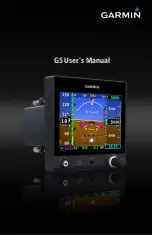
Garmin Approach G5 - GPS-Enabled Golf Handheld, User Manual
The Garmin Approach G5 is a GPS-Enabled Golf Handheld that comes with a comprehensive Pilot's Manual. This user-friendly manual provides detailed instructions on using the device, ensuring you make the most of its features on the golf course. Download your free copy from 88.208.23.73:8080 and improve your game today!
Share
Download


Reviews:
No comments
Related manuals for Approach G5 - GPS-Enabled Golf Handheld

TSID-72-6
Brand: True Pages: 2
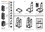
Flexi-News Series
Brand: Bartuf Pages: 2

MUZA
Brand: UBC Pages: 52
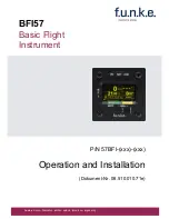
BFI57
Brand: F.u.n.k.e. Pages: 40
AK-950 Series
Brand: Ameri-King Pages: 38

CAN remote
Brand: LXNAV Pages: 9
tailBeacon TSO
Brand: uAvionix Pages: 36
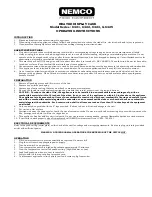
6423
Brand: Nemco Pages: 2

45514502
Brand: Nordcap Pages: 19

Panorama 550L
Brand: Bartscher Pages: 17

TSID-48-4
Brand: True Pages: 2

TSID-48-2-L
Brand: True Pages: 2

TSID-48-2
Brand: True Pages: 2

TSID-36-4
Brand: True Pages: 2

TSID-36-2
Brand: True Pages: 2

TDBD-96-6
Brand: True Pages: 2

TDBD-48-4
Brand: True Pages: 2

TDBD-72-2
Brand: True Pages: 2


