background image

190-02102-00

August 2021

Revision 4

G1000 NXi Integrated Avionics System

Line Maintenance Manual

Kodiak 100

System Software Version 2633.00 or later

 2634.00 or later

Uncontrolled if Printed

Summary of Contents for Cessna Caravan G1000

Page 1: ...190 02102 00 August 2021 Revision 4 G1000 NXi Integrated Avionics System Line Maintenance Manual Kodiak 100 System Software Version 2633 00 or later 2634 00 or later Uncontrolled if Printed...

Page 2: ...BLANK PAGE Uncontrolled if Printed...

Page 3: ...ision hereto is strictly prohibited Garmin G1000 NXi FliteCharts and SafeTaxi are registered trademarks of Garmin International Inc or its subsidiaries Garmin SVT is a trademark of Garmin Internationa...

Page 4: ...DIATE PRESENCE OR ASSISTANCE OF ANOTHER PERSON CAPABLE OF RENDERING AID WARNING THIS PRODUCT ITS PACKAGING AND ITS COMPONENTS CONTAIN CHEMICALS KNOWN TO THE STATE OF CALIFORNIA TO CAUSE CANCER BIRTH D...

Page 5: ...ic rays high energy particles originating from outside of our atmosphere and device memory SEU occurrences are more com mon at high altitudes due to the proximity to where the cosmic rays origi nate T...

Page 6: ...Garmin and or its third party providers and is protected under the United States of America copyright laws and international copyright treaties You further acknowledge that the structure organization...

Page 7: ...5 2 2 4 GMA 1360D Audio Panel 2 6 2 2 5 GMC 710 AFCS Controller 2 6 2 2 6 GIA 63W GIA 64W Integrated Avionics Unit 2 7 2 2 7 GEA 71 and GEA 71B Engine and Airframe Interface 2 7 2 2 8 GTX 345R Transp...

Page 8: ...nt Cards 3 19 3 8 Crossfill Monitoring System 3 21 3 8 1 Crossfill Troubleshooting 3 25 3 9 Software and Configuration Load Troubleshooting 3 26 3 9 1 System Communication Hierarchy 3 27 3 10 Maintena...

Page 9: ...rocessor Troubleshooting 4 67 4 7 8 GRS 79 GMU 44B AHRS Troubleshooting 4 75 4 7 9 GDC 72 Air Data Computer Troubleshooting 4 88 4 7 10 GTP 59 Outside Air Temperature Probe Troubleshooting 4 89 4 7 11...

Page 10: ...te Loading Procedures 6 6 6 6 GDU 1050A Display Unit 6 6 6 7 GMA 1360D Audio Panel 6 6 6 8 GEA 71 71B Engine and Airframe Interface Unit 6 6 6 9 GTX 345R Transponder 6 6 6 10 GRS 79 AHRS GMU 44 B Magn...

Page 11: ...r Pitch and Roll Trim Adjustments 7 36 7 11 GFC 700 TESTING 7 37 7 11 1 Preflight Test 7 37 7 11 2 AFCS Switch Checks 7 38 7 11 3 Autopilot Clutch Overpower Check 7 40 7 11 4 Manual Electric Trim Spee...

Page 12: ...02 00 Rev 4 8 14 1 GSA 80 81 Greasing Procedure 8 2 8 15 GSM 86 Servo Gearbox 8 3 8 15 1 GSM 86 Servo Gearbox 8 3 8 15 2 Slip Clutch Torque Check Procedure and Servo Current Display Check 8 3 8 15 3 G...

Page 13: ...figuration LRU Testing and Calibration LRU Periodic Maintenance Line maintenance involves identification and replacement of a faulty LRU The LRU is sent to Garmin for further diagnosis and repair Comp...

Page 14: ...min Technical Support Contact Garmin at the following for technical support Garmin Aviation Support Hours 7 am to 7 pm CT Monday Friday Phone 1 866 739 5687 Fax 1 913 397 8282 Email avionics garmin co...

Page 15: ...latest revision of this manual can be accessed in the Dealer Resource Center at dealers garmin com 1 11 Activation of Garmin Connext Satellite Services Activation of a GSR 56 or GDL 69A SXM unit for...

Page 16: ..._________________________________________________________ ____________________________________________________________________________ Page 1 4 LMM for the Kodiak 100 190 02102 00 Rev 4 BLANK PAGE Unc...

Page 17: ...evel block diagrams are shown in Figure 2 1 and Figure 2 2 Table 2 1 Kodiak 100 G1000 NXi System LRUs Part Number LRU Type Qty 011 03470 00 GDU 1050 Display Unit Standard 3 011 03595 00 Flight Stream...

Page 18: ...l 1 011 03997 00 GWX 75 Airborne Weather Radar Optional 1 011 03177 10 GDL 69A SXM Satellite Radio Receiver Optional 1 011 03177 15 GDL 69A SXM Satellite Radio Receiver Optional 1 011 00877 20 GSA 80...

Page 19: ...____________________________________________ ____________________________________________________________________________ LMM for the Kodiak 100 Page 2 3 190 02102 00 Rev 4 Figure 2 1 Kodiak 100 Block...

Page 20: ...____________________________________________ ____________________________________________________________________________ Page 2 4 LMM for the Kodiak 100 190 02102 00 Rev 4 Figure 2 2 Kodiak 100 Block...

Page 21: ...a Wi Fi and Bluetooth capable multimedia card installed in the bottom SD card slot of an MFD It sends position velocity time attitude heading FIS B TIS B traffic Sirius XM audio control Sirius XM wea...

Page 22: ...so allows independent volume adjustments for the pilot copilot and passengers Additionally there is a volume adjustment for the MKR AUX MUSIC and TEL sources A failsafe circuit connects the pilot head...

Page 23: ...ded by the GEA 71 B Engine airframe instrumentation is also displayed on the PFDs and or MFD when the system is in reversionary mode The displays serve as the GEA 71 B user interface All configuration...

Page 24: ...OAT probe This unit provides pressure altitude airspeed vertical speed and OAT information to the system and it communicates with both GIAs the PFDs the MFD and the AHRS It also interfaces directly wi...

Page 25: ...A bottom directional antenna installation gives the benefit of intruder bearing visibility for targets that are shaded from the top directional antenna 2 2 14 GWX 75 Airborne Weather Radar Processor...

Page 26: ...the GRS 79 AHRS The motor control board processes this incoming data and drives the brushless motor as necessary to obtain the desired aircraft response The monitor board independently monitors the se...

Page 27: ...00 Rev 4 2 3 System Operation 2 3 1 G1000 NXi System Controls Control and operation of G1000 NXi equipment as normally used in flight occurs through the PFD and MFD bezel controls the GMA 1360D Audio...

Page 28: ...transceiver standby frequencies large knob for MHz small knob for kHz Press to toggle cyan tuning box between COM1 and COM2 The selected COM green is controlled with the COM MIC key Audio Panel 7 COM...

Page 29: ...GDU Softkeys 12 Dual FMS Knob Press to turn the selection cursor On Off Data Entry With cursor on turn to enter data in the highlighted field large knob moves cursor location small knob selects charac...

Page 30: ..._____________________________ ____________________________________________________________________________ Page 2 14 LMM for the Kodiak 100 190 02102 00 Rev 4 2 3 1 3 GMA 1347 Audio Panel Controls Fig...

Page 31: ...y pressing the COM1 Key 4 COM2 When selected the 2 COM receiver audio can be heard 5 COM 3 MIC Not used 6 COM 3 Not used 7 COM 1 2 Not used 8 TEL Not used 9 PA Selects the passenger address system The...

Page 32: ...Pressing selects the pilot intercom isolation Press again to deselect pilot isolation 21 COPLT Pressing selects the copilot intercom isolation Press again to deselect copilot isolation 22 PILOT Knob...

Page 33: ...___________________________ ____________________________________________________________________________ LMM for the Kodiak 100 Page 2 17 190 02102 00 Rev 4 2 3 1 4 GMA 1360D Audio Panel Controls Figu...

Page 34: ...er audio can be heard 5 AUXMIC Reserved for optional audio 6 AUX Reserved for optional audio 7 DME Turns optional DME audio On or Off 8 NAV1 When selected the 1 NAV receiver audio can be heard 9 ADF T...

Page 35: ...udio source can only be assigned to one source at a time Once the Bluetooth audio is assigned to an audio source the remaining entertainment audio sources will only cycle between OFF and WHITE 17 SPKR...

Page 36: ...or is not active press to switch to Blue Select mode If the volume control cursor is active press twice once to cancel the cursor twice to activate Blue Select mode Press and hold for five seconds to...

Page 37: ...illuminated Table 2 5 AFCS Control Unit GMC 710 1 HDG Key Selects deselects Heading Select Mode 2 APR Key Selects deselects Approach Mode 3 NAV Key Selects deselects Navigation Mode 4 FD Key Activate...

Page 38: ...lects Vertical Navigation mode 13 ALT SEL Knob Sets the selected altitude in the Selected Altitude Box In addition to providing the standard altitude alerter function selected altitude provides an alt...

Page 39: ...Wings Level The AHRS should display valid attitude and heading fields typically within one minute of system start The AHRS can align itself both while taxiing and during level flight When the MFD sta...

Page 40: ..._____________________________ ____________________________________________________________________________ Page 2 24 LMM for the Kodiak 100 190 02102 00 Rev 4 Figure 2 8 PFD Initialization both PFDs F...

Page 41: ...ration in which all important flight information is presented identically on the displays closest to the red DISPLAY BACKUP button The left hand audio panel forces PFD1 and the MFD to display the same...

Page 42: ...ls to detect a display problem Reversionary mode can be manually activated by pressing the red DISPLAY BACKUP button on the audio panel Pressing this button again deactivates Reversionary Mode 2 3 5 C...

Page 43: ...ngs up an options menu for the field or in some cases allows the operator to enter data for the field To confirm a selection press the ENT key To cancel a selection press the small FMS knob Pressing t...

Page 44: ...ACTV softkey this copies the SET column to the LRU unit s configuration memory The settings then become the ACTIVE settings for the LRU being configured Figure 2 14 SET ACTIVE Diagram Technicians can...

Page 45: ...e files are loaded to LRUs from the PFD System Upload page in configuration mode Table 2 6 Data Transmission Indicators The LRU is online and reports the item located next to the indicator box is comm...

Page 46: ...and various options Configuration files contain preset selections for input output channels aircraft specific settings and LRU specific settings CAUTION Certain software and configuration files are R...

Page 47: ...Xi is designed to store all configuration settings in various places so the configuration of the system is retained in the aircraft during maintenance Figure 2 15 and Figure 2 16 show a block diagram...

Page 48: ...ch loader card s part number defines all files found on the card for a specific installation Approved loader card part numbers are found in SN21 01 Kodiak 100 G1000 Software Configurations and Updates...

Page 49: ...ID code and after that can only be used to re enable a feature on the same system If a customer purchases one of these cards and a qualified Garmin dealer uses it to enable a feature according to appr...

Page 50: ...h compatible and authorized Garmin offers blank replacement cards These blank cards do not contain any preloaded aviation databases and are intended for operators who have already purchased databases...

Page 51: ...ing does not resolve the issue before reloading contact Garmin Avi ation Support to find another solution to the fault if one exists 3 1 Loader Cards NOTE The system requires the use of SanDisk SD car...

Page 52: ...nd render the card unusable Garmin advises using the following procedure to disable ReadyBoost 1 Plug a flash drive or other removable media device non Garmin SD card into the computer 2 In the AutoPl...

Page 53: ...center Run the program to make an SD card for use in the aircraft 2 Open the PFD1 MFD and PFD2 circuit breakers 3 Place the digital signature update card in the top slot of the display that requires...

Page 54: ...crew profiles and flight plans please refer to the relevant Kodiak 100 Pilot s Guide for the software that is being loaded All user page settings will also revert to their default values Software is l...

Page 55: ...y with existing modifications CAUTION Do not allow power to be removed from the system when loading software Remove power only when instructed by the following procedures As a general rule all display...

Page 56: ...onfiguration card loader from the MFD and insert it into the top card slot on PFD1 Repeat Steps 2 through 5 for PFD1 12 While holding down Softkey 12 on the MFD restore power to the MFD by closing the...

Page 57: ...Figure 3 5 006 B2633 0 X Loader Card Example Figure 3 6 006 B2634 0 X Loader Card Example 4 Once the Group choice is selected the cursor moves to the ITEM window Turn the small FMS knob to activate th...

Page 58: ...4 Figure 3 8 006 B2634 0 X Loader Card Example Figure 3 9 006 B2634 0 X Loader Card Example Figure 3 10 Options Selection 5 Press the CHK All softkey 6 For aircraft that do not have Garmin GMA 1347 13...

Page 59: ...done this way on the first load there wont be a copy 8 Press the LOAD softkey 9 Monitor the loading progress and make sure the software load completes without errors as indicated by the following a Gr...

Page 60: ...d Quest Kodiak Aerocet 6650 Float Option Load this option only if Aerocet 6650 floats are installed Quest Kodiak Float Removal Option Load this option only if Wipline or Aerocet floats are removed fro...

Page 61: ...this option only if GTS 800 Dual Antenna Traffic Awareness System has been installed Quest Kodiak Air Conditioning Installation Option Load this option only if the Air Conditioning System has been ins...

Page 62: ...installed on the aircraft Quest Kodiak TKS Ice Protection Cargo Pod Option Load this option only if FIKI system with tank in cargo pod is installed on the aircraft Quest Kodiak Dual ENG Inlet Actuator...

Page 63: ...Option Load this option only if a Flight Stream 510 is going being used Quest Kodiak Fuel Level Indication Load this option only if the float type fuel quantity sensors are installed Quest Kodiak ELT...

Page 64: ...structed to do so A failed or canceled load may result The first step is to do an inventory of the hardware installed on the aircraft so a successful software load can be completed A review of the Kod...

Page 65: ...2 on PFD2 restore power to PFD2 by closing PFD2 circuit breaker NOTE The following procedures are for 2634 05 loader cards 3 5 1 01 Baseline Software and Configuration Loading Load software version 26...

Page 66: ...d Complete COMPLETE is in the summary box 8 Select Delete if the Detected new LOG window appears 9 Press the ENT key to acknowledge the UPLOAD COMPLETE box 10 After completing the 01 Baseline Group an...

Page 67: ...ipped with the GWX70 Weather Radar Load when equipped with the GWX Processor GWX75 or GWX80 10 Airborne Traffic GTS 800 Dual Antenna GTS 800 Single Antenna Load when equipped with the GTS800 and 2 ant...

Page 68: ...634 07 and later Load when equipped with the WX500 Stormscope system This option configures RS 232 Channel 4 on both GIAs to output GPS data This option used to be titled Fish and Wildlife and may be...

Page 69: ...ds in the GROUP field Press the ENT key 5 Once any of the Kodiak Options are selected and the cursor moves to the ITEM field turn the small FMS knob to generate a pick list Move the cursor to highligh...

Page 70: ...cable feature on one system one aircraft A new enablement card must be used for each feature on each aircraft 3 Insert the TAWS enablement card in the upper slot of the PFD1 4 While holding the ENT ke...

Page 71: ...is possible the other devices may not have received the entire configuration When these devices are powered on with missing or invalid configuration they may revert to a default safe configuration an...

Page 72: ...This is because an offline device could cause the problem the monitoring system was meant to prevent if it did not receive the configuration or if it received only partial configuration Figure 3 16 Up...

Page 73: ...being offline Figure 3 18 Crossfill Summary The Crossfill Monitor waits indefinitely for crossfill to complete but after 10 minutes it displays a message advising the technician that something may be...

Page 74: ...n though timeout has occurred crossfill still proceeds normally and if the Crossfill Monitor detects the network has synced all of the config tags it will still show a completion message even after ti...

Page 75: ...sible corrections for a timeout include the following a Ensure that all configured LRUs are on and in config mode b Ensure that all online LRUs can be seen by the uploading device on the network The S...

Page 76: ...D is not touched during the loading process unless specifically instructed to do so Ensure that LRU part number is compatible with software version and Loader Card Replace LRU Configuration file load...

Page 77: ...ode Table 3 5 System COM Hierarchy Desired Operation Criteria for Success Load Software to GDU 1050 MFD or PFD Displays G1000 NXi Kodiak 100 Loader Card must be inserted in top slot for each display t...

Page 78: ...the ENT Key or the right most softkey on MFD display to acknowledge the startup screen 6 Turn the large FMS Knob and select Aux 7 Turn the small FMS Knob and select Databases 8 Monitor the Sync Statu...

Page 79: ...rn the large FMS Knob and select Aux 14 Turn the small FMS Knob and select the Databases 15 Make sure the standby databases transferred and are now in the Active column Figure 3 24 Aux Databases Page...

Page 80: ...atabase information for each display Use the small FMS Knob to scroll through the database information Press the ENT Key or the FMS Knob to exit 3 12 Final Configuration Items 3 12 1 Aircraft Registra...

Page 81: ...1 Turn the small FMS knob to select Transponder Airframe Config page 12 Make sure the GTX 3x5 1 box at the top of the page is checked green and the tail number ICAO address and VFR code that were ente...

Page 82: ...Flow window 4 Enter the five digit K Factor calculated in the above section as follows a Turn the inner FMS knob to select the first digit b Turn the outer FMS knob to move the cursor to the right one...

Page 83: ...nt UTC date and time 4 Press the ENT key 3 12 5 Sidetone Setting For aircraft with GIA 63W units installed only 1 Select the GIA COM SETUP PAGE in the GIA Page Group 2 Press the FMS knob The SELECT GI...

Page 84: ..._________________________________________________________ ____________________________________________________________________________ Page 3 34 LMM for the Kodiak 100 190 02102 00 Rev 4 BLANK PAGE Un...

Page 85: ...lt Reporting and Built In Testing In addition to the troubleshooting information presented in this section it should be noted that Garmin LRUs carry out Built In Test BIT and performance checks on a f...

Page 86: ...on items associated with the unsuccessful data The following section describes common system annunciations Causes may include but are not limited to Unavailable Data Unreliable Data Failed Data due t...

Page 87: ...3 1 NAV1 or COM1 Numbers 1 4 1 Check for GIA1 configuration software or failed data path error messages Correct any errors before proceeding 2 Switch GIA1 and GIA2 to verify the location of the probl...

Page 88: ...movement rocking the wings or moving the tail may cause the attitude and heading to fail if it believes the aircraft is in motion without GPS input Check if the GPS has acquired at least four satelli...

Page 89: ...y of the GDC 72 pitot static plumbing 2 Inspect the pitot static ports and associated equipment for faults 3 Check the GTP 59 probe if there is a TAS failure 4 Check the GDC 72 configuration settings...

Page 90: ...led data path error messages Correct any errors before proceeding 2 Make sure metal objects tool boxes power carts etc are not interfering with the magnetometer Make sure the aircraft is not in a hang...

Page 91: ...onfiguration software or failed data path error messages Correct any errors before proceeding 2 Make sure the airplane is located where its GPS antennas have a clear view of the sky 3 Check for possib...

Page 92: ...ace the GTP 59 4 3 14 GS Number 14 Same as 4 3 1 and 4 3 2 4 3 15 IAS Number 15 1 Check the PFD for PFD1 2 MFD or GDC1 2 configuration software or failed data path error messages Correct any errors be...

Page 93: ...100 Page 4 9 190 02102 00 Rev 4 Figure 4 2 Failure Annunciations MFD 4 3 16 FLAPS Number 16 1 Check the flap position GEA 71 GEA 71B wiring 2 Replace the GEA 71 GEA 71B 4 3 17 ELEV Number 17 1 Check t...

Page 94: ...12V TKS Flow Sensor TKS QTY Sensor Fuel Sensors Fuel Flow Sensor Aileron Trim Servo 10V Pitot and Stall Heat Current Sensors Fuel OFF Indication 4 The configuration and calibration boxes should be che...

Page 95: ...possible causes and recom mended actions Table 4 1 Troubleshooting System Messages System Message Description Possibly Faulty LRU Subsystem ADC1 ALT EC ADC1 altitude error correction is unavailable G...

Page 96: ...voltage to the GIA 64W Wiring COM1 INOP INTRL A GIA internal fault GIA 64W COM1 MANIFEST COM1 software mismatch GIA 64W COM1 PTT The COM1 push to talk PTT key line is stuck in the enabled state GIA 64...

Page 97: ...The COM2 remote transfer key line is stuck in the enabled state GIA 64W COM2 SERVICE A fault has been detected in the COM subsystem of GIA2 GIA 64W COM2 INOP SERL A COM Serial Communication fault GIA...

Page 98: ...e mismatch Communication halted GDC 72 GEA1 CM INOP COMM GEA1 Configuration Module connection GEA 71B Master Config Module GEA1 CONFIG GEA1 configuration error GEA 71B Master Config Module GEA1 INOP C...

Page 99: ...Internal GIA Serial Communication Fault VOR ILS Receivers Aircraft supply voltage to the GIA 64W GIA 64W GIA 1 INOP VOLT Check GIA voltage Aircraft supply voltage to the GIA 64W GIA 64W GIA1 MANIFEST...

Page 100: ...A 2 INOP VOLT Check GIA voltage Aircraft supply voltage to the GIA 64W GIA 64W GIA2 MANIFEST GIA2 software mismatch GIA 64W GIA2 SERVICE A fault has been detected in GIA2 GIA 64W GMA 1 CONFIG GMA1 con...

Page 101: ...k Recommended GIA 64W GPS NAV LOST A loss of GPS navigation has been detected due to position error GIA 64W GPS NAV LOST A loss of GPS navigation has been detected due to GPS failure GIA 64W GPS NAV L...

Page 102: ...the MFD1 bezel GDU 1050 MFD1 MANIFEST MFD1 software mismatch GDU 1050 MFD1 SERVICE A fault has been detected in MFD1 GDU 1050 MFD1 VOLTAGE MFD1 has low voltage GDU 1050 NAV 1 INOP CAL Check NAV Calibr...

Page 103: ...etected in the NAV subsystem of GIA2 GIA 64W PFD1 BACKLIGHT CAL PFD1 backlight calibration lost GDU 1050 PFD1 CONFIG PFD1 configuration error GDU 1050 Master Config Module PFD1 COOLING PFD1 has poor c...

Page 104: ...tachment including visual inspection of mounting rack and other supporting structure attaching the rack to aircraft structure For installations using countersunk fasteners verify the fastener heads ar...

Page 105: ...Check the integrity of the SHIELD BLOCK ground attachments to the harness connector assembly as well as the integrity of the individual shields and their attachment 4 6 1 4 GMA 1347 GMA 1360D Audio P...

Page 106: ...connector and support structures to ensure that no corrosion chaffing cracks or other defects exist Check the servo control chain to ensure no link deformation corrosion or other damage exists If the...

Page 107: ...ning strike to the aircraft the GA 58 Antenna s and its associated installation shall be inspected If the GA 58 Antenna was struck by lightning then the antenna and the surrounding installation shall...

Page 108: ...recommended actions Table 4 2 GDU 1050 System Messages System Message Cause Recommended Actions CNFG MODULE The PFD1 master configuration module is inoperative Check the master configuration module c...

Page 109: ...to the GDU If the fault persists check the master configuration module harness for faults and replace if necessary MFD1 COOLING MFD1 has poor cooling Reducing power usage Check the avionics environme...

Page 110: ...ng Reducing power usage Check the avionics environment for proper cooling and make any necessary corrections If the fault persists replace the GDU PFD1 KEYSTK A key is stuck on the PFD1 bezel Select t...

Page 111: ...witch it with a known good unit to see if the problem remains with the display Replace the display if the condition remains with the same unit 4 If the fault remains in the original position after swi...

Page 112: ...s on the GDU are perpendicular to the connector If not straighten them before reseating the connector 6 Ensure the GDU is receiving power and ground If a circuit breaker is tripped find the source of...

Page 113: ...1 3 Garmin SVT Synthetic Vision Technology Troubleshooting The optional Synthetic Vision Technology SVT is a visual enhancement to the G1000 NXi SVT depicts a forward looking attitude display of the t...

Page 114: ...ata Heading data GPS position data 4 9 Arc second Terrain data Obstacle data TAWS function is not available in test mode or failed The position of the aircraft exceeds the range of the terrain databas...

Page 115: ...state Cycle power to the unit Press the PTT switch to cycle its operation Check the PTT switch and wiring Check the GIA to GMA interconnect If the fault persists replace the GMA COPILOT PTT STUCK GMA...

Page 116: ...ists remove and replace the GMA GMA 1 INOP VOLTAGE Voltage outside standard range The GMA is inoperative due to a voltage fault Cycle power to the unit Verify GMA cooling Check aircraft supply voltage...

Page 117: ...audio panel configuration settings do not match backup configuration memory Reload configuration to the GMA If the problem persists replace the GMA If the problem persists check the configuration modu...

Page 118: ...an be adjusted on the GMA configuration page for higher noise environments 10 Replace the unit only after all possible external sources of noise have been eliminated 4 7 2 3 Speaker Cuts Out Reduce th...

Page 119: ...____________________________________ ____________________________________________________________________________ LMM for the Kodiak 100 Page 4 35 190 02102 00 Rev 4 Figure 4 5 GMA Configuration Page...

Page 120: ...nd provide it to the OEM or Garmin for assistance with further troubleshooting Table 4 5 GIA 64W System Messages System Message Cause Recommended Actions AHRS1 GPS AHRS1 using the backup GPS path The...

Page 121: ...or GIA1 and GIA2 on the GPS Status page If the message persists replace the GIA with no GPS reporting If the message persists replace the GSU AHRS1 GPS AHRS1 is not receiving backup GPS information En...

Page 122: ...cannot acquire a position lock troubleshoot the GPS Check GIA GSU interconnect If the fault persists replace the GRS COM1 CONFIG COM1 configuration error Reload configuration to the GIA If the fault p...

Page 123: ...sts replace the GIA COM1 INOP INTRL The COM subsystem of GIA1 is inoperative due to an internal fault Cycle power to the GIA Retrieve the log from CMC fault folder If the fault persists replace the GI...

Page 124: ...IA COM1 RMT XFR The COM1 remote transfer key line is stuck in the enabled state Press the remote transfer switch to cycle operation Check the remote transfer switch and wiring If the fault continues r...

Page 125: ...ecessary If the fault persists replace the master configuration module If the fault persists replace the GIA COM2 INOP CAL The COM subsystem of GIA1 is inoperative due to loss of factory calibration L...

Page 126: ...emote transfer switch to cycle operation Check the remote transfer switch and wiring If the fault continues replace the GIA COM2 SERVICE A fault has been detected in the COM subsystem of GIA2 COM2 may...

Page 127: ...ure has been detected in the Glideslope subsystem of GIA2 The receiver may still be available Cycle power to the GIA Replace the GIA GIA1 CONFIG The GIA1 configuration settings do not match the backup...

Page 128: ...tion Fault COM Transceiver Cycle power to the GIA Check aircraft supply voltage to the GIA Check supply voltage s at GIA Main power supply inputs The minimum operational voltage is 9 VDC Replace the G...

Page 129: ...configuration memory Reload configuration to the GIA If the problem persists check the configuration module harness for faults and replace if necessary GIA2 CONFIG GIA2 has an error in the audio conf...

Page 130: ...osition error Verify the area the aircraft was traveling through did not have loss of GPS coverage FAA NOTAM may be issued for periods of outage or the US Coast Guard website will have notices posted...

Page 131: ...he GIA with a WAAS capable unit LOI GPS information loss of integrity has been detected Verify the area the aircraft was traveling through did not have loss of GPS coverage FAA NOTAM may be issued for...

Page 132: ...folder Replace the GIA NAV1 MANIFEST NAV1 software mismatch Load the correct software NAV1 RMT XFR The NAV1 remote transfer key line is stuck in the enabled state Press the NAV1 remote transfer switch...

Page 133: ...bling for faults NAV2 INOP SERL An internal NAV serial communication fault Check data bus wiring Check status of the other LRU Retrieve log from CMC fault folder Replace the GIA NAV2 INOP SYNTH NAV sy...

Page 134: ...nas The GPS antenna is less susceptible to harmonic interference if a 1 57542 GHz notch filter is installed on the COM transceiver antenna output Locate the GIA as far as possible from all COM antenna...

Page 135: ...is not generally performed during installation or maintenance It can be used to adjust COM receiver 25 0 kHz 8 33 kHz squelch settings if needed If the COM squelch opens after performing the procedure...

Page 136: ...tly stored into incorrect memory locations requiring GIA replacement 7 Activate the cursor and select the desired tuning frequency Only the frequencies 118 00 MHz 127 00 MHz and 136 975 MHz can be use...

Page 137: ...quired satellites before the other or one of the GPS receivers has not yet acquired an SBAS Satellite Based Augmentation System signal While the aircraft is on the ground the SBAS signal might be bloc...

Page 138: ...hich actual position has 95 probability of laying EPU is a statistical error indication and not an actual error measurement DOP measures satellite geometry quality i e number of satellites received an...

Page 139: ...er has excluded the satellite Fault Detection and Exclusion D Indication Denotes the satellite is being used as part of the differential computations Each satellite has a 30 second data transmission t...

Page 140: ...ouch Enter b Select CLR NV at the bottom of the screen using the Softkey Select control on the GTC and touch Select c Touch Select on the GTC The Clear GIA nonvolatile memory pop up window is displaye...

Page 141: ...position Reload the GIA audio and configuration files Also reload the configuration files for any optional equipment which is installed on the aircraft that require the GIA configuration to be updated...

Page 142: ...ratic weak open the GIA2 and COM2 circuit breakers If the problem is resolved the GPS2 antenna has failed If the GPS2 signal strength bars are erratic weak open the GIA1 and COM2 circuit breakers If p...

Page 143: ...GEA 71B System Messages System Message Cause Recommended Actions GEA1 CONFIG GEA1 configuration error Reload configuration to the GEA GEA1 MANIFEST GEA1 software mismatch Load the correct software GEA...

Page 144: ...proper operation if applicable Shutdown the LRU for 15 minutes Cycle the power If the fault persists remove and replace the GEA GEA 1 INOP SENS CNFG Check GEA software and configuration The GEA is in...

Page 145: ...r Configuration Module harness for faults and replace if necessary 8 Replace the thermocouple of the GEA 9 Allow the GEA to warm up if the operating temperature is thought to be too high 10 If it is t...

Page 146: ...rmanent records for a list of the interfaced equipment and system configuration data When troubleshooting the GTX refer to the wire routing drawings and interconnect wiring diagrams that are retained...

Page 147: ...___________________________________ ____________________________________________________________________________ LMM for the Kodiak 100 Page 4 63 190 02102 00 Rev 4 Figure 4 12 GTX 3x5R General Troubl...

Page 148: ...ng the USB tool the GTC Processor is configured correctly for the desired display GTS Install Tool won t display any pages Improper wiring circuit breaker open Ensure USB is properly wired to the GTS...

Page 149: ...each other Ensure that power and ground connections to the GPA 65 are connected in their proper place Verify input voltage and if it continues return to Garmin for service 1030 MHz Fault 1090 MHz Fau...

Page 150: ...n the transponder and the GTS Radio Altitude Fault Radio Altimeter is not powered on or improper wiring Improper configuration settings Verify the radio altimeter has power and is properly wired Verif...

Page 151: ...ANTENNA FOR PERSONNEL NEAR AN OPERATING AIRBORNE WEATHER RADAR THE MINIMUM SAFE DISTANCE IS BASED UPON THE FCC EXPOSURE LIMIT AT 9 3 TO 9 5 GHZ FOR GENERAL POPULATION UNCONTROLLED ENVIRONMENTS WHICH...

Page 152: ...ROM THE 10 ANTENNA 9 6 FT FROM THE 12 ANTENNA AND 14 FT FROM THE 18 ANTENNA AS INDICATED IN THE ILLUSTRATION BELOW ALL PER SONNEL MUST REMAIN OUTSIDE OF THIS ZONE THE DISTANCE TO THE MPEL BOUNDARY IS...

Page 153: ...ING TAKE THE FOLLOWING PRECAUTIONS TO PREVENT HUMAN BODY DAMAGE WARNING NEVER STAND NEARBY OR IN FRONT OF A RADAR ANTENNA WHICH IS TRANSMITTING THE DANGER INCREASES WHEN THE ANTENNA IS NOT SCANNING WA...

Page 154: ...other faults require the radar to be actively used and are not retained upon reset Table 4 10 GWX Processor Troubleshooting Fault Indication Cause Solution Electrical Status Indicator Voltages within...

Page 155: ...and allow it to cool before further use If the condition occurs on the ground and the temperature is normal in the radome replace the GWX Not viewable in config mode RX TX Status Indicator Receiver T...

Page 156: ...ace the GWX Viewable in config mode Attitude Status Indicator Valid attitude information is not being received on neither HSDB ARINC nor analog Verify the unit is properly connected to the systems AHR...

Page 157: ...e interference Remove radome Inspect interior surfaces of the radome for contact with the radar dish Correct interference by adjusting or replacing radome If no radome interference is found perform th...

Page 158: ...message is on radar page The system does not detect the presence of the GWX Make sure the GWX is receiving power and ground Check the GWX connector for security If the GWX communication path passes t...

Page 159: ...des of operation are available and depend upon the combination of available sensor inputs see Figure 4 15 Loss of air data GPS or magnetometer sensor inputs is communicated to the pilot by message adv...

Page 160: ...te the magnetic field model AHRS1 CAL AHRS1 calibration error Calibrate the AHRS per Section 7 6 AHRS1 CONFIG AHRS1 configuration error Reload configuration to the AHRS If the fault persists check the...

Page 161: ...iving backup GPS information Ensure no device using cell phone Wi Fi or Bluetooth technology is turned on even in a monitoring state in the aircraft cabin Check the GPS status for GIA1 and GIA2 on the...

Page 162: ...RS2 configuration error Reload configuration to the AHRS If the fault persists check the configuration module wires for faults and replace if necessary If the fault persists replace the master configu...

Page 163: ...iving backup GPS information Ensure no device using cell phone Wi Fi or Bluetooth technology is turned on even in a monitoring state in the aircraft cabin Check the GPS status for GIA1 and GIA2 on the...

Page 164: ...AHRS2 TAS The GRS 79 is not computing valid airspeed Check the pneumatic plumbing If the problem persists replace the GRS Table 4 13 GMU 44 System Messages System Message Cause Recommended Actions GM...

Page 165: ...ir Data Input Failure Failure of the air data input has no affect on the AHRS output while AHRS is receiving valid GPS information Invalid unavailable airspeed data in addition to GPS failure results...

Page 166: ...Make sure no cell phone or device using cell phone technology is turned on in the cabin even in a monitoring state Make sure the four GRS 79 mounting screws are tight Finger tight is not sufficient A...

Page 167: ...5 GRS 79 Inputs and Outputs GRS 79 Input GRS 79 Output GRS 79 Mode GPS Data GMU 44B Data CPS Data Heading Pitch Roll Primary Good Good Doesn t Matter Valid Valid Valid Reversion No GPS Bad Good Good V...

Page 168: ...last Was it brief or sustained Was it repetitive in nature If it was repetitive about how many times did it happen Did it happen on more than one day 5 Was the fault correlated with a specific maneuv...

Page 169: ...crews e Check the area of the GRS for any heavy objects that might not be fastened tight to the structure which could induce GRS vibration f Look for evidence of water or fluid contamination in the ar...

Page 170: ...the aircraft 15 Replace the GRS 16 If the problem persists replace the GRS configuration module 17 Contact Garmin Aviation Support for additional assistance if the condition is not resolved 4 7 8 11 H...

Page 171: ...ircraft is on the ground and stationary the aircraft yaw rate must be less than 1 5 degrees second to use GPS track information to calculate heading This logic is applied regardless of magnetic anomal...

Page 172: ...e Incorrect software might have been loaded to the GDC Load the correct software ADC1 AS EC ADC1 airspeed error correction is unavailable Incorrect software might have been loaded to the GDC Load the...

Page 173: ...erature Probe Troubleshooting Inspect the GTP 59 for dirt accumulation corrosion and other damage Clean or replace as required Check the GTP 59 wiring and connectors for faults or damage The GTP 59 ha...

Page 174: ...subscriptions respectively These IDs are in the following locations The SiriusXM Info Screen on Touchscreen Controllers The XM Satellite Radio Activation Instructions included with the unit the label...

Page 175: ...ure the GDL 69A wiring is correct and the circuit breaker is closed Ensure the Remote Power On discrete P691 pin 77 is not pulled above 3 volts Improper configuration Ensure the control display device...

Page 176: ...7 12 1 AFCS Annunciations The AFCS Annunciation field is located above the altimeter tape on the PFD as shown in Figure 4 17 No audio output No audio output from GDL 69A Improper wiring Check wiring...

Page 177: ...working order Check specifically for proper operation of the following GIA 64W Integrated Avionics Unit GRS 79 AHRS GDC 72 Air Data Computer All Servos Verify no red X is displayed Verify no related m...

Page 178: ...affected servo is receiving power Check the servo wiring and connector If the failure condition still exists remove and replace the affected servo If the AP is engaged take control of the aircraft and...

Page 179: ...ialization started the PFT will fail After the system PFT has passed it will be performed again if a servo resets if the autopilot servo breaker is reset or the cross side GIA restarts it Typically th...

Page 180: ...to view their logs 5 Using the FMS knob choose VIEW MAINTENANCE LOG in the COMMAND window 6 Press the ENT key 7 When the Maintenance Log data starts to display in the OUTPUT window you might see More...

Page 181: ...cription of the possible values for STEP on the failed GIA and corrective actions AHRS MON invalid STATE The AHRS monitor has detected the AHRS data is invalid The possible values for STATE are Mon Pr...

Page 182: ...es the servo configuration specified in the certification gain file Reload the gain files to correct 4 7 12 3 4 PFT Step 3 System Initializing Verify Selected Side This step checks to verify the PFD i...

Page 183: ...ep checks to verify the cross side GIA is online and communicating with all servos from ARINC 485 data lines The cross side GIA must also pass its AHRS monitoring Ensure both GIAs are online and commu...

Page 184: ...Step 15 Verify Cross GIA PFT is Completed This step checks to verify the cross side GIA is also on Step 14 Cycle power on all GIAs and servos Ensure the PFD and MFD are turned on 4 7 12 3 17 PFT Step...

Page 185: ...nly way to clear this state would be to cycle unit power The second grouping of faults can occur during normal mode These faults generally cause a disconnect of power to the GSA and report that a faul...

Page 186: ...mal mode These faults generally cause a disconnect of power to the GSA and report that a fault has occurred to the GIA The Notes column indicates any actions that can be taken to troubleshoot the prob...

Page 187: ...IL Check unit power and AP Disconnect power HALL 5 FAIL Check unit power and AP Disconnect power HALL 6 FAIL Check unit power and AP Disconnect power CURR OFFSET FAIL Check unit power and AP Disconnec...

Page 188: ...data to allow it to continue scrolling down the screen pressing any key will not continue disregard the text instruction you to do so Continue to scroll through all the OUTPUT data until you see the...

Page 189: ...13 Insert the SD card in the card reader of a laptop or desktop computer and open the diag_buf_log txt file from the SD card using the WordPad program Verify that all of the fault logs were downloaded...

Page 190: ...pressing the FMS knob select the desired in the LRU and press the ENT key 4 Press the DNLD LOG softkey Figure 4 20 5 Monitor the Assert Log Download Box 6 Press the ENT key when the box shows 100 7 R...

Page 191: ...aft Report is a human readable report generated by the G1000 NXi system to publish pertinent information about the system see Figure 4 21 This report can be used to assist with engineering squawk inve...

Page 192: ...aft report file is automatically generated on the top slot of all PFD MFD units This file is available in a human readable csv format An equivalent file in encrypted zip format is also generated This...

Page 193: ...will be flagged for export on the next power cycle The export is triggered if there is a valid connection available for the PED based App Note that a newly generated Aircraft Report file will overwri...

Page 194: ...guration option for any source setup can be easily copied to a Garmin approved blank SD card using configuration mode interface Please get in touch with the Garmin sales person to order the Garmin app...

Page 195: ...card version to confirm the system being imported is as desired 4 Select Yes when prompted to import the system 5 The PFD should restart in configuration mode on the System Import page 6 Confirm the i...

Page 196: ..._______ ____________________________________________________________________________ Page 4 112 LMM for the Kodiak 100 190 02102 00 Rev 4 Figure 4 22 MFD Aux Maintenance Logs page 3 Select the folder...

Page 197: ..._______________ LMM for the Kodiak 100 Page 4 113 190 02102 00 Rev 4 4 Press the Export Button and then press OK Figure 4 24 Selected File Exporting 5 Once the Status indicates Exported the file will...

Page 198: ...________________________________________________________ ____________________________________________________________________________ Page 4 114 LMM for the Kodiak 100 190 02102 00 Rev 4 BLANK PAGE Un...

Page 199: ...ng access to LRUs NOTE Certain LRU connectors include Garmin backshell assemblies Garmin backshells gives the installer the ability to easily terminate shield grounds at the backshell housing Refer to...

Page 200: ...with the instrument panel The locking studs should be oriented with the alignment marks in the vertical position for installation 1 To Remove a Using a 3 32 hex drive tool turn all four 1 4 turn fast...

Page 201: ...o Remove a Using a 3 32 hex drive tool turn the hex nut counterclockwise until the GMA 1347 is unlocked from its location b Carefully remove the GMA 1360D 1347 from its rack 2 To Reinstall a Visually...

Page 202: ...tem 1 To Remove a Loosen the Phillips screw or pull on the D Ring and twist counter clockwise 90 for units with a D Ring b Unlock the handle and remove the unit from the rack NOTE The install screw is...

Page 203: ...3 32 hex drive tool to turn each of the four locking sockets turn clockwise This may require applying a small amount of forward pressure to engage the turn sockets 5 2 5 GRS 79 Attitude and Heading R...

Page 204: ...specifications may result in a failed magne tometer calibration The mounting screws must be brass 2 To Reinstall a Connect the wiring harness to the GMU b Lower the GMU 44 44B into the rack and secur...

Page 205: ...b Slide the GDC 72 forward to remove from the remote rack 2 To Reinstall a Place the GDC 72 with endplate mount assembly installed on the remote rack b Slide the GDC 72 back with endplate mount assem...

Page 206: ...pect the connectors for damaged pins b Gently push the unit into the rack to engage the connectors c Push the unit lever down towards the bottom of the unit avoiding the use of excessive force d If th...

Page 207: ...harness NOTE When inserting the unit into the remote mounting rack it may be possible for the pivot pin to fit between the unit and the mount rack without going into the slot of the locking plate If t...

Page 208: ...se damage to both the connectors and coaxial cable e Loosen the unit hold down clamp by turning it counterclockwise until it disen gages the unit hold down tab f Pull the unit up slightly at an angle...

Page 209: ...of the rack to make sure there are no bent or damaged pins Repair any damage found b Insert a 3 32 hex drive tool into the access hole in the front of the unit c Turn the hex drive tool counterclockwi...

Page 210: ...12 LMM for the Kodiak 100 190 02102 00 Rev 4 2 To Reinstall a Place the ring terminal over the end of the sensor b Insert the sensor and ring terminal into the hole in the aircraft skin c Slide the wa...

Page 211: ...while loosening attachment nuts Be sure to support the radar unit as the fasteners are removed b Remove the weather radar from the bulkhead assembly by removing the socket head cap screws c Remove th...

Page 212: ...removed to access all the Pitch Trim servo attachment bolts d Carefully remove the servo and place a protective cover on the output gear e Place a protective cover over the GSM 86 Servo Gearbox 2 To R...

Page 213: ...taminated unit s to Garmin for repair CAUTION Do not disassemble the servo actuator or servo mount There is no require ment or provision for routine maintenance lubrication or field repair of the serv...

Page 214: ...00 190 02102 00 Rev 4 5 2 16 Configuration Module Replacement Figure 5 1 Configuration Module Installation Figure 5 2 Configuration Module Kit 011 00979 03 1 To Remove a Disconnect the connector 1 fro...

Page 215: ...on Instructions a If the GRS 79 AHRS Configuration Module is replaced all three GRS GMU calibration procedures must be performed Refer to Section 7 6 b If the GDC 72 Configuration Module is replaced c...

Page 216: ...le Removal and Replacement The GEA 71B has a K Type thermocouple Item 1 shown below installed in its back shell in addition to the configuration module The thermocouple is used in conjunction with the...

Page 217: ...imp pins item 2 onto each of the thermocouple wires item 1 Ensure that pre stripped wire length is 1 8 before crimping b Insert newly crimped pins and wires into the appropriate connector housing loca...

Page 218: ..._________________________________________________________ ____________________________________________________________________________ Page 5 20 LMM for the Kodiak 100 190 02102 00 Rev 4 BLANK PAGE Un...

Page 219: ...continued failures stop performing the procedures in this section and perform the procedure described in Section 3 Loading System Software And Configuration using the Transaction Log on the Transacti...

Page 220: ...rocedures Power loss during software loading can corrupt an LRU requiring replacement Both displays should be in the same mode configuration or normal unless instructed differently 6 2 Transaction Log...

Page 221: ...onfiguration error messages 1 Replace the faulty LRU hardware according to the procedures in Section 5 2 Start the system in configuration mode 3 Select the LRU Replacement Page 4 Press the FMS knob T...

Page 222: ...Reloading Verification Once an LRU software reloading procedure has been performed the technician can confirm the system has been successfully returned to its previously approved state by using the Co...

Page 223: ...The internally saved loader cards are used by LRU Software and Configuration loading procedure The Card Copy operation uploads the loader card into the PFD internal memory A newly uploaded loader car...

Page 224: ...50 new serial number is installed the correct software and configura tion files must be loaded to the unit Refer to Section 3 6 7 GMA 1360D Audio Panel No software configuration loading is required if...

Page 225: ...oaded Follow the instructions in Section 3 to load the GMU software file 6 11 GDC 72 Air Data Computer No software or configuration loading is required if the removed GDC 72 is reinstalled If a new GD...

Page 226: ..._________________________________________________________ ____________________________________________________________________________ Page 6 8 LMM for the Kodiak 100 190 02102 00 Rev 4 BLANK PAGE Unc...

Page 227: ...other LRUs This causes the attitude airspeed and altitude fields to be invalid during the first approximately 40 60 seconds of applying system power 2 Check the displays for the following a Check that...

Page 228: ...should have valid altitude airspeed vertical speed COM1 COM2 NAV1 NAV2 and engine instruments h De activate the pilot side reversion mode by pushing the DISPLAY BACKUP button Make sure PFD1 and MFD re...

Page 229: ...uld normally acquire a GPS navigation solution within 5 to 10 minutes of startup provided the aircraft is outside or indoors with a GPS repeater Select the Aux GPS Status page on the MFD Two softkeys...

Page 230: ...signal strength levels 6 During the transmit period make sure the GPS INTEG flag does not come into view on the PFD and that GPS1 does not lose a 3 D navigation solution on the MFD 7 Repeat Step 5 and...

Page 231: ...n radial 000 with a course width of 20 Make sure full scale deflection of the CDI while applying a 10 deviation signal Exercise the CDI with both right and left deviations for both NAV 1 and 2 Exercis...

Page 232: ...7 3 2 Transceiver Operational Check Perform a ramp test radio check by exercising the installed transceivers microphone microphone key and audio over the headphones and speaker Make sure that communi...

Page 233: ...ignal is present over the headphones and speaker 2 Make sure the outer middle and inner annunciations appear on the PFD when the corresponding signal is applied Marker beacon annunciations appear at t...

Page 234: ...icators digital displays and slide bars Green bands and displays indicate normal ranges of operation amber and red bands and displays indicate caution and warning respectively When unsafe operating co...

Page 235: ...a 7 5 1 Transponder Ground Test 1 Make sure no GTX errors are displayed and the GTX controls are responding 2 Place the MFD and PFD 2 into NORMAL MODE 3 Place PFD1 into CONFIG MODE 4 Go to the System...

Page 236: ...X mode 5 Using the transponder test set make sure the following ADS B Out parameters are being transmitted a Aircraft emitter category is Light Airplane 15 500 lbs on the TR 220 this is indicated as A...

Page 237: ...e Check Check the outside air temperature OAT measurement shown on the PFD to ensure it reads ambient temperature 7 5 5 GRS GMU Calibration Procedure After mechanical and electrical installation of th...

Page 238: ...ual Entry Manually enter zeros for Pitch Roll Offsets passcode required This procedure should be used only if leveling the aircraft is not feasible and the AHRS is mounted to within 0 25 of aircraft...

Page 239: ...Mag netic Interference with GMU 44 Required for initial installation certification This test should also be repeated to ensure all subse quent electrical changes associ ated with devices within 10 0...

Page 240: ...is detected it must be resolved and the magnetometer calibration procedure must be repeated Wiring or grounding changes associated with a device located in the same wing as the GMU 44 B is a good exa...

Page 241: ...flashing The FMS small knob can now be used to select which calibration validation procedure to run 4 Select PITCH ROLL OFFSET then press the ENTER key If the PITCH ROLL OFFSET selection is still flas...

Page 242: ...re A 1 or A 2 is repeated then Procedure B must also be repeated NOTE Calibration Procedure B must be carried out at a location that is determined to be free of magnetic disturbances such as a compass...

Page 243: ...e calibration Press the following softkeys in sequence 9 10 11 12 3 Press the FMS inner knob to highlight GRS1 and press the ENT key 4 After selecting GRS1 the SELECT PROCEDURE field will begin flashi...

Page 244: ...the ENTER key on the PFD to conclude this procedure NOTE A magnetometer calibration failure is indicated by a Calibration Error mes sage In the event of a failure make sure the installation passes the...

Page 245: ...ration Test Calibration Procedure D is required for all installations to validate the vibration characteristics of the installation Calibration Procedures A 1 through C are not required before this pr...

Page 246: ...ity of GRS 79 and or GMU 44 B mechanical mounting with respect to the airframe Vibrational motion of GRS 79 and or GMU 44 B caused by neighboring equipment and or supports Mounting of GRS 79 at a loca...

Page 247: ...f the certification data Furthermore Calibra tion Procedure E should be performed once every 12 months on at least one production aircraft for every airframe type or model equipped with the G1000 syst...

Page 248: ...es Only the electronic devices that are likely to affect the oper ation of the GMU 44 44B magnetometer need be included in the test sequence The list of relevant electronic devices varies from aircraf...

Page 249: ...he operator has completed the actions specified in the test sequence press the ENTER key to indicate the process is complete When this is done the TEST COMPLETE field stops flashing 4 The PFD informs...

Page 250: ...NOTE Typically a compass rose is an acceptable location to perform the magne tometer calibration procedure However because not all compass roses are well maintained even an existing compass rose shoul...

Page 251: ...AT SITE NOT UNIFORM or MAG FIELD AT SITE DIFFERS FROM IGRF MODEL message the site contains magnetic disturbances that are too large NOTE The Magnetometer Calibration Procedure must consistently repor...

Page 252: ...EA from the HSCM ENABLED GEA selection box see Figure 7 7 Figure 7 7 HSCM Enabled GEA Selection Box d Select the appropriate channel from the HSCM ENABLED GEA I O CHANNEL selection box Make sure the d...

Page 253: ...ly calibrate the channel assuming the shunt is properly set up for calibration see Step 0 c CALIBRATION CORRECTED VALUE the output of the GEA channel if the above offset were applied should always be...

Page 254: ...test per the procedures in the OEM approved Aircraft Maintenance Manual NOTE The GDC will not provide valid outputs until the aircraft post installation cal ibration procedures are completed 7 8 GDL 6...

Page 255: ...s when aircraft radio or marker beacon activity is heard Audio is always soft muted when an interruption occurs from these sources Soft muting is the gradual return of audio to its original volume lev...

Page 256: ...nel 1 when complete 3 Using the volume control located in the cabin make sure you can increase and decrease the XM radio volume the volume bar at the bottom of the screen will show changes to the volu...

Page 257: ...Page 1 Turn the large FMS Knob to select the Map Page Group 2 Turn the small FMS Knob to select the Weather Data Link Page 3 Select the available softkeys to select the desired SiriusXM Weather produ...

Page 258: ...Another is to install an air data test set with an altitude of 10 000 and 150 Kts of airspeed 4 Press the Test softkey 5 Use a ramp tester such as a TIC TR220 or equivalent to make the following setu...

Page 259: ...ftkey indicated green on the MFD press the TAS OPER softkey Each time the GTS Processor transitions between these modes a self test of the antenna circuit is initialized If the antenna connection is n...

Page 260: ...roximate traffic 14 Toggle intruder traffic to standby or off 15 Reposition ramp test set and directional antenna to a starboard position of 90 degrees 16 Reengage the same intruder scenario as above...

Page 261: ...s are correctly installed on cables Correct antenna type is selected in the configuration NOTE If multiple targets are displayed during the antenna tests recheck the antenna coaxial connections 7 10 G...

Page 262: ...s manual confirm the configuration so the system does not display configuration error messages The following procedure assumes the correct configuration files have been loaded to the GWX 1 Select the...

Page 263: ...ill make sure the proper operation of the GFC 700 AFCS The technician performing these checks must be thoroughly familiar with the GFC 700 refer to the Garmin G1000 Kodiak 100 Pilot s Guide 7 11 1 Pre...

Page 264: ...ed direction Check operation in both the up and down direction 2 While actuating both sections of the manual electric pitch trim switch press and hold the AP DISC TRIM INTRPT switch Verify the trim st...

Page 265: ...key Open NO 1 GPS NAV circuit breaker Verify the autopilot disconnects with a continuous aural alert and a flashing red white AP annunciation Press the AP YD DISC TRIM INTRPT switch to cancel the aler...

Page 266: ...s running restrain the aircraft pitch trim wheel and verify the trim clutch can be overpowered If it cannot be overpowered check the GSM 86 clutch cartridge Refer to the pitch trim servo installation...

Page 267: ...nd the control wheel begins moving aft 5 While holding the control wheel firmly press and hold the CWS button to re synchronize the pitch reference Re center the control wheel to wings level and mid r...

Page 268: ...side by pressing the XFR button The arrow that is illuminated indicates which side is coupled No flight director modes should be active at this time 5 On the MFD turn the inner FMS knob to activate th...

Page 269: ...y 12 15 On the MFD turn the inner FMS knob to activate the AUX SYSTEM SETUP page 16 On the MFD AUX SYSTEM SETUP page press the SETUP 2 softkey 17 Verify that on the MFD SETUP 2 page there is a window...

Page 270: ...libration procedure cannot be performed during a single power cycle perform the last two steps in this procedure before the aircraft master power switch is turned off The four subsets should be indent...

Page 271: ...ght most RIGHT softkey d Flap Trim i Press RESET softkey 3 Press ENT ii Move the trim nose down all the way until it hits the stop iii Press the left most DN softkey iv Move the trim nose up all the w...

Page 272: ...ation 7 12 2 1 Fuel Temperature Configuration The fuel temperature sensor is integrated into the Right Wing fuel sensor The Fuel Temp L Offset must be set for the fuel quantity to display on the EICAS...

Page 273: ...ay be pulled to deactivate the tone Ensure both circuit breakers are re activated after this procedure is completed 3 Turn all three displays on in Configuration mode by pushing and holding the ENT ke...

Page 274: ...e bottom of the outboard filler cap with Jet A or Jet A1 fuel ensuring the aircraft remains in a 2 7 0 2 nose up and 0 0 0 1 roll attitude A full tank is defined as just enough fuel to cover the anti...

Page 275: ...ress the ENT key to select OK 16 Reset any circuit breakers pulled during the procedure 17 Turn the master switch to the OFF position 18 Proceed to the Verification procedure 7 12 2 4 Verification 1 T...

Page 276: ..._________________________________________________________ ____________________________________________________________________________ Page 7 50 LMM for the Kodiak 100 190 02102 00 Rev 4 BLANK PAGE Un...

Page 277: ...TS 800 is on condition only 8 4 GDC 72 Air Data Computer Periodic Maintenance Per Part 43 Appendix E paragraph b 2 Garmin specifies a test procedure equivalent to Part 43 Appendix E paragraph b 1 with...

Page 278: ...ion Verification Verify each audio suppression input for proper operation Verify the GDL 69A SXM audio to the crew headphones is muted when each connected warning alarm system is activated When possib...

Page 279: ...ate of GSM 86 units except for GSM 86 part numbers 011 01904 03 and 011 01904 04 in which there are no O ring seals in the back plate If it is found during installation removal or reinstallation of a...

Page 280: ...t values are not lost by changing configuration mode pages NOTE Perform the following test at temperatures between 50 F and 120 F 1 Use the FMS knob to select the desired servo 2 Verify the PFT status...

Page 281: ...erify the current displayed is greater than zero 11 After the data is collected and processed the test displays the results of the first direction on the PFD The servo immediately begins to drive in t...

Page 282: ...15 630 in lbs f Yaw right minimum allowed torque is 97 026 in lbs and maximum is 115 630 in lbs g Up pitch trim minimum allowed torque is 57 462 in lbs and maximum is 68 320 in lbs h Down pitch trim m...

Page 283: ...he clutch Check control friction against aircraft mainte nance specifications If the same result is received on retest remove servo gearbox and check set clutch on stand SERVO TORQUE TOO LOW The servo...

Page 284: ...rvo has failed to transmit load cell sensor status Repeat test again If message does not clear troubleshoot the servo and it s wiring for the source of the failure If message does not clear troublesho...

Page 285: ...ory and cannot be adjusted in the field 1 Part Number 011 01908 00 Roll Servo a GSM 86 with 61 in lb clutch 1 16 spiral capstan b Tolerance of 15 2 Part Number 011 01908 01 Pitch and Yaw Servos a GSM...

Page 286: ...hrough its full range of motion it should be moved sufficiently both directions to find the slip clutch of the servo actuator is being overridden 8 While moving the control yoke be sure the servo moto...

Page 287: ..._________________________________________________________ ____________________________________________________________________________ LMM for the Kodiak 100 Page 8 11 190 02102 00 Rev 4 BLANK PAGE Un...

Page 288: ...Uncontrolled if Printed...
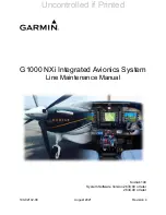
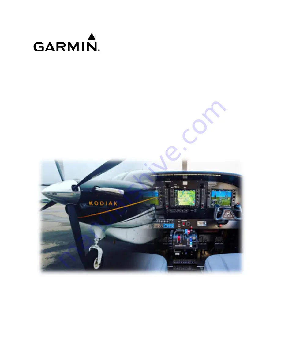
Reviews: