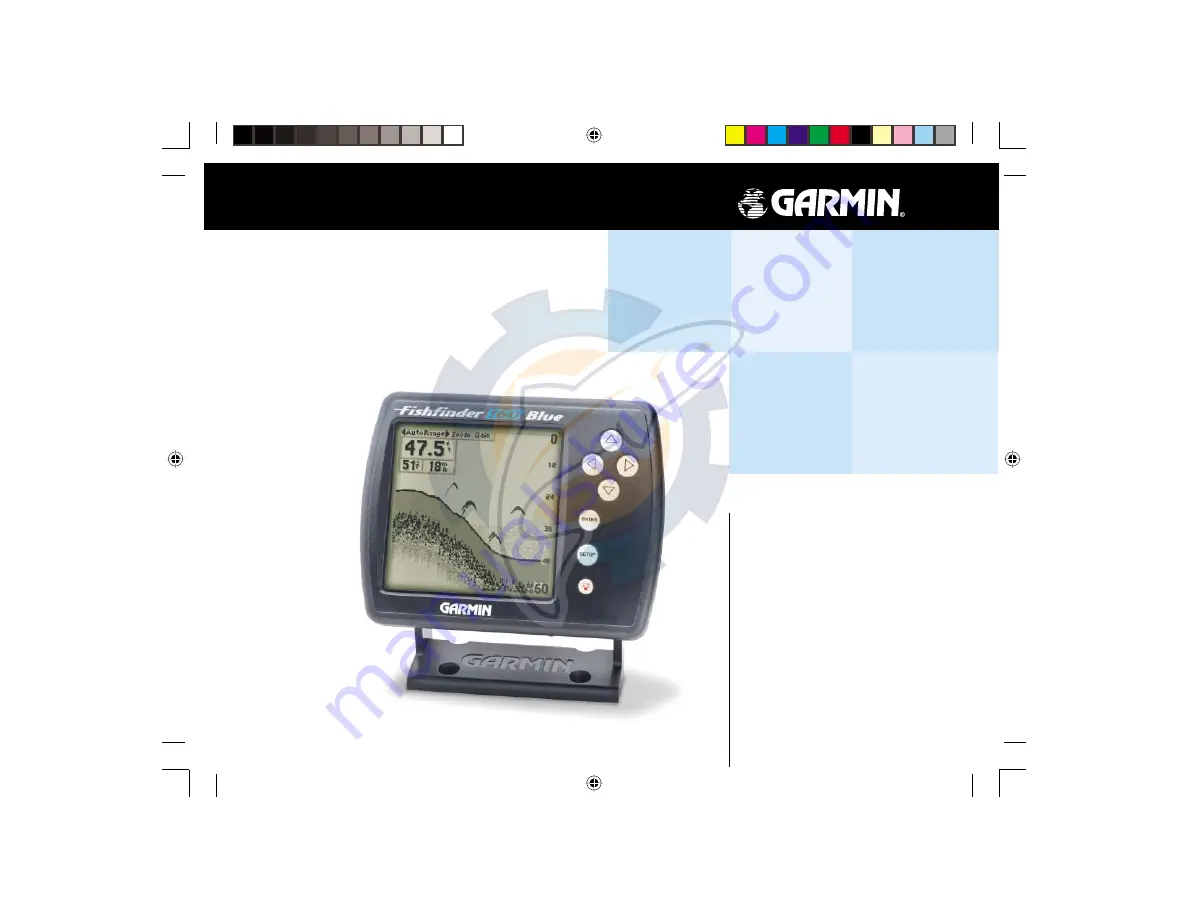
background image

owner’s 

manual

Fishfi nder 160 Blue

FF 160 Blue covers.indd

12/13/01, 2:56 PM

1

www.reelschematic.com

www.reelschematic.com

Summary of Contents for Fishfinder 160 Blue

Page 1: ...owner s manual Fishfinder 160 Blue FF 160 Blue covers indd 12 13 01 2 56 PM 1 www reelschematic com www reelschematic com ...

Page 2: ...iewed for personal use provided that such electronic or printed copy of this manual contains the complete text of this copyright notice and provided further that any unauthorized commercial distribution of this manual is strictly prohibited Information in this manual is subject to change without notice GARMIN Corporation reserves the right to change or improve its products and to make changes in t...

Page 3: ...ou for choosing the GARMIN Fishfinder 160 Blue This product is designed for easy operation and to provide years of reliable service Please take the time to read this Owner s Manual and learn the opera tion of your new unit This will help ensure that you get the most from the Fishfinder 160 Blue If you encounter a problem or just have a question contact our Product Support Department at 913 397 8200 ...

Page 4: ...LL GARMIN BE LIABLE FOR ANY INCIDENTAL SPECIAL INDIRECT OR CONSEQUENTIAL DAMAGES WHETHER RESULTING FROM THE USE MISUSE OR INABILITY TO USE THIS PRODUCT OR FROM DEFECTS IN THE PRODUCT SOME STATES DO NOT ALLOW THE EXCLUSION OF INCIDENTAL OR CONSEQUENTIAL DAMAGES SO THE ABOVE LIMITATIONS MAY NOT APPLY TO YOU To obtain warranty service call the GARMIN Customer Service department 913 397 8200 or 800 80...

Page 5: ...or Optional Dual Frequency Transducers and Accessories Plastic Transom Mount with depth temp Bronze Thru Hull depth only Plastic Thru Hull depth only Speed Sensor Temperature Sensor 10 Transducer Extension Cable 20 Transducer Extension Cable Second Mounting Station Flush Mounting Kit Swivel Mount 1 RAM Cigarette Lighter Adapter Power Data Cable 18 Pin A C PC Adapter US 18 Pin A C PC Adapter EURO I...

Page 6: ... Tab Number Size 20 Battery Voltage 21 Temperature 21 Speed 22 Depth Number 22 Introduction i vi Customer Service i Limited Warranty ii Packaging and Accessories iii Unit Display vi Installation 1 9 Transducers 1 Transom Mount Installation 2 In hull Installation 3 Speed Sensor Installation 4 Wiring Harness Installation 5 Wiring to a Fuse Block 5 Display Installation Surface Mount 7 Display Install...

Page 7: ...te Speed 27 Units Tab Depth 28 Temperature 28 Speed 28 Memory Tab Remember 29 Factory Setup 29 Software Version 29 On the Water 30 35 Understanding Sonar 30 Transducer Coverage 31 Understanding the Chart 32 Whiteline 33 Thermoclines 34 Simulator Mode 35 Appendix A Specifications 36 Appendix B Alarm Messages and Icons 37 Appendix C Index 38 FF 160 B Rev B indd 12 13 01 2 49 PM 5 www reelschematic co...

Page 8: ... fish is detected Thermocline and Structure With GARMIN s See Thru technology the Fishfinder 160 Blue can display more than just the thermocline and structure The unit displays fish in and below the thermocline trees brush and deadfall like you have never seen before Bottom Shape and Type Garmin s unique DCG Depth Control Gain system provides a clear graphic representation of the bottom type and its ...

Page 9: ...suits the water that you are on With a dual frequency transducer you may select either a 200kHz frequency a 50kHz frequency or both The 50kHz frequency setting provides a wide cone angle This wide cone angle produces a large coverage area but less detailed bottom resolution In areas where bottom contours change quickly this can result in dead zones where fish cannot be seen In contrast the 200kHz ...

Page 10: ... fittings water intake or discharge ports or anything that creates air bubbles or causes the water to become turbulent It is important that the transducer be in calm non turbulent water for optimal performance Do not mount transducer directly in the path of the prop The transducer can cause cavitation that may degrade the boat s performance and damage the prop Make sure that the transducer is below...

Page 11: ...s to be solid fiberglass devoid of any air bubbles laminates fillers or dead air space The location needs to be in an area of clean water at all speeds Do not place the transducer over any strakes or behind any obstruction on the hull that would create turbulence Testing the Location Place the transducer in the water pointed directly at the bottom and set the unit for optimum performance Place the t...

Page 12: ...speed sensor installation instructions to assemble the speed sensor with the mounting bracket drill holes in the transom mount the assembly and route the cable Installing the Transducer OK Adjust the speed sensor so it is parallel with the bottom of the boat If the speed sensor is not adjusted properly the sonar may experience inaccurate or degraded speed readings Strip Caulk or RTV Sealer Slow cu...

Page 13: ...to wire the unit directly to an unused holder on your current fuse block If you are using the boat s fuse block remove the in line fuse holder supplied with the unit Installing the Wiring Harness 1 Determine the polarity of the fuse holder using a Test Light or Volt Meter 2 Install the Red wire on the Positive Fuse Holder Terminal 3 Install the Black wire on the Negative Fuse Holder Terminal 4 Ins...

Page 14: ...pment If equipped with a capable transducer and speed sensor the Fishfinder 160 Blue sends depth temperature and speed information that could be displayed on another device 2 Amp In Line Fuse BLUE NMEA Out NMEA Device Power Source BLACK Ground RED 10 to 15 VDC TRANSDUCER CONNECTION Connecting a Transducer to Multiple Sensors Installing the Wiring Harness Speed Temp Transducer Power Data er Data Con...

Page 15: ...r mounting holes with a pencil 3 Drill pilot holes for the mounting fasteners not included in kit 4 Secure the Surface Mount Bracket using the mounting fasteners 5 Slip the unit into the Surface Mount Bracket 6 Tighten the knobs to secure the unit to the bracket The Surface Mount Bracket is designed to be secured using a flat head screw If you use a screw with a countersunk head you risk damaging t...

Page 16: ...5 64 drill 4 Using a 1 7 8 hole saw cut the center relief 5 Secure the unit to the mounting surface using four M5 screws If you are flush mounting the unit on a sheet metal surface use the mounting bracket on the back to help reinforce the metal You may also purchase the optional Flush Mounting Kit and follow the flush mounting instructions included with the kit Mounting Bracket Be careful not to in...

Page 17: ... installation gradually increase the boat s speed while checking the unit operation If the unit displays intermittently or fails to display verify that the transducer and speed sensor are aligned parallel with the bottom If necessary adjust their heights until the unit operates correctly It may be necessary to make several adjustments to ensure proper operation throughout the speed range If the si...

Page 18: ... or change Setup Key The SETUP key is used to activate deactivate the Setup Menu Power and Backlight Key The POWER key is used to turn the unit on off and to activate the display backlight Press and hold to turn the unit on or off Pressing the POWER key briefly will activate the backlight or change the backlight setting There are three backlight settings Off Medium and High FF 160 B Rev B indd 12 1...

Page 19: ...layed from top to bottom along the right side of the display Messages and Alarm Icons are displayed along the bottom If the unit is unable to track the bottom for any reason the digits in the depth window will flash on and off to alert the user that the unit is not tracking the bottom Describing The Display Adjustment Bar Battery Voltage Water Temperature Speed Over Water Depth Line Flasher Alarm M...

Page 20: ...tings before making a change press the ENTER key to activate the adjustment list Range The Range Adjustment is used to set the display depth range The unit can be set to automatically track the bottom or set to a user specified depth range To select a Depth Range 1 Highlight Range on the Adjustment Bar 2 Using the UP or DOWN Arrow place the pointer at the desired depth range To set the unit to aut...

Page 21: ... other than No Zoom is selected This setting allows you to select a specific area to view on the display or allows the unit to automatically select a viewing area based on the bottom To change the View 1 Highlight View on the Adjustment Bar 2 Press the UP or DOWN Arrows to change the setting To have the unit automatically set a View 1 Highlight View on the Adjustment Bar 2 Using the UP or DOWN Arr...

Page 22: ...ity by selecting a higher gain If there is too much detail or if the screen is cluttered lowering the sensitivity may increase the clarity of the display To change the Gain 1 Highlight Gain on the Adjustment Bar 2 Using the UP or DOWN Arrows move the pointer to the desired setting Minimum Gain Normal Gain Maximum Gain The Adjustment Bar FF 160 B Rev B indd 12 13 01 2 49 PM 14 www reelschematic com...

Page 23: ...e highlight between the tab selections Press the RIGHT arrow to access the selection fields Each time the Setup Menu is accessed the unit will return to the last edited selection field Press the LEFT arrow key to get back to the tabs Chart Tab The Chart tab allows the user to determine the appearance of the scrolling chart display To access the Chart tab place the highlight over it using the arrow...

Page 24: ...ency mode combines the improved contour detail and depth readings of the 200kHz frequency with the wide coverage area of the 50kHz frequency To select a Frequency 1 Highlight the Chart tab on the Setup Menu 2 Highlight the Frequency selection field and press ENTER 3 Using the UP or DOWN Arrow choose 200kHz 50kHz or Dual and press ENTER The selected frequency will be displayed in the bottom left han...

Page 25: ... feature To change the Whiteline Setting 1 Highlight the Chart tab on the Setup Menu 2 Highlight the Whiteline selection field and press ENTER 3 Choose On or Off and press ENTER to accept the selection Scroll Speed You can adjust the speed that the chart scrolls from right to left by using the Scroll Speed selection field If you are sitting still or the chart is moving too fast slowing the scroll ra...

Page 26: ...entify a set depth or to measure the depth of underwater objects The Noise Reject and Flasher tools are used to enhance the chart and help in identifying and providing information about an underwater return The Simulator tool is used to enhance the simulator mode by allowing you to customize the simulated transducer selection To access the Tools tab place the highlight over it using the arrow keys...

Page 27: ...ld and press ENTER 3 Select On or Off and press ENTER to accept the selection Simulator The Simulator tool allows the unit to simulate the use of four different transducer configurations Depth Only Temp Speed or Temp and Speed These choices allow the user to view more accurate depictions of actual unit operation For details on using the simulator see page 35 Noise Reject The Noise Reject tool help...

Page 28: ... you to choose whether you would like to see normal or large numbers on the chart You can also configure the unit to display Battery Voltage water Temperature and Speed Over Water if the unit is equipped with capable sensors You can also set up how the unit finds the digital Depth Number To access the Numbrs tab place the highlight over it using the arrow keys Number Size This setting determines t...

Page 29: ...e water temperature when equipped with a temperature sensing transducer The unit has the ability to automatically sense when a temperature capable transducer is connected The temperature field can be shown or hidden regardless of the transducer installed To set the Temperature display field 1 Highlight the Numbrs tab on the Setup Menu 2 Highlight the Temperature selection field and press ENTER 3 Cho...

Page 30: ...t to Auto the unit will show the most accurate digital depth possible However this may cause the chart to update slower as the unit calculates the Auto depth When set to From Chart default the unit finds the digital depth from the same image you see on the chart The From Chart setting allows the chart to update faster than when the unit is set to Auto and is recommended when using the unit in deep...

Page 31: ...ing the arrow keys See page 37 for alarm icons and messages Fish Alarm The Fish Alarm can be configured to sound by fish size There are four different alarm selections Off Small Medium and Large Medium and Large or Large The Fish Alarm will sound with or without the Fish Symbols activated on the Chart Tab of the Setup Menu To set a Fish Alarm 1 Highlight the Alarms tab on the Setup Menu 2 Highlight ...

Page 32: ...eys to input the desired depth then press ENTER to accept the setting Deep Water The Deep Water Alarm can be set to sound a warning at a depth determined by the user The alarm must be activated before the unit will sound a warning To activate deactivate the Deep Water Alarm 1 Highlight the Alarm tab on the Setup Menu 2 Highlight the Deep Water checkbox 3 Pressing ENTER will insert or remove a chec...

Page 33: ...e desired voltage then press ENTER to accept the setting System Tab The System tab contains the Contrast Beeper NMEA Output and Language setups To access the System tab use the arrow keys to highlight it Contrast The display Contrast may need to be adjusted to compensate for light levels or viewing angles To adjust the Contrast 1 Highlight the System tab on the Setup Menu 2 Highlight the Contrast ...

Page 34: ...To activate deactivate the NMEA Output 1 Highlight the System tab on the Setup Menu 2 Highlight the NMEA Output field and press ENTER 3 Choose Off or On then press ENTER to accept the setting Language The Fishfinder 160 Blue can display chart information in several differ ent languages To select a Language 1 Highlight the System tab on the Setup Menu 2 Highlight the Language field and press ENTER 3 U...

Page 35: ...ter Type 1 Highlight the Calibrt tab on the Setup Menu 2 Highlight the Water Type selection field and press ENTER 3 Choose Fresh or Salt then press ENTER to accept the selection Calibrate Speed The Calibrate Speed field will be enabled when a speed sensor is installed or when you are in simulator mode This allows you to calibrate the Fishfinder speed to your boat s speedometer or to your GPS speed To...

Page 36: ...er temperature in Fahrenheit F or Celsius C To Select a Temperature Unit 1 Highlight the Units tab on the Setup Menu 2 Highlight the Temperature field and press ENTER 3 Select Fahrenheit or Celsius then press ENTER to accept the setting Speed If equipped with a speed sensor the unit can display the boat s Speed Over Water The unit can be configured to display Miles Per Hour mh Kilometers Per Hour kh...

Page 37: ...member field and press ENTER 3 Choose All or Setup Only then press ENTER to accept the selection Factory Setup To restore the Factory Settings 1 Highlight the Memory tab on the Setup Menu 2 Highlight the Factory Setup button and press ENTER 3 Choose OK to reset the unit or Cancel to abort Software Version The Software Version Button will report information about the current software version in the ...

Page 38: ...idebar demonstrates this showing an underwater scene as it would be displayed on the chart Generally speaking if the only thing between the transducer and a flat bottom is water the first strong return will come from the bottom directly below the transducer this return will set the bottom level Weaker secondary returns provide the detailed data Stronger returns will display in darker colors with b...

Page 39: ... at a 30 foot depth When using the Fishfinder 160 Blue in Dual frequency mode the unit transmits both 50kHz and 200kHz signals at the same time The Dual frequency capability of the Fishfinder 160 Blue allows the user to have a large coverage area and still retain good bottom resolution When in Dual frequency mode the unit uses the 200kHz to display detailed bottom information keeping Dead Zones to...

Page 40: ...sh and tree are side by side as shown in Example 1 However when we look at Example 2 we see that the fish can be several feet from the tree It is important to remember that the Fishfinder cannot determine where in the coverage area the tree or fish are only that the returns were received at the indcated depths in the same time frame Example 1 Remember that the Fishfinder displays a 2 D picture of the ...

Page 41: ... the bottom type the black return makes this more difficult With the Whiteline active the bottom return appears layered in shades of gray and black which makes determining the bottom type easier and more reliable Example 3 shows the bottom return with and without the Whiteline activated Whiteline Turned Off Whiteline Activated Hard Bottom Soft Bottom Whiteline Whiteline can also help you to determi...

Page 42: ...r rate than the water above it The thermocline is usually displayed as a gray level as shown below One of the unique features offered by GARMIN is See Thru technology A benefit of See Thru technology is that it allows the Fishfinder 160 Blue to see fish inside thermoclines Thermocline FF 160 B Rev B indd 12 13 01 2 50 PM 34 www reelschematic com www reelschematic com ...

Page 43: ...ibed below The unit will indicate that it is running in simulator mode by displaying a message across the bottom of the screen The message will be replaced by the S simulator mode icon in the lower left corner of the screen The unit can be configured to act as if a variety of transducers are installed while in the simulator mode To Select a Simulated Transducer 1 Press the SETUP button on the face...

Page 44: ...merged to 1 meter for 30 minutes Power Input 10 to 18 VDC with High Voltage Protection Usage 12 watts maximum Nominal 12 VDC 0 8 amps Performance Sonar Power Output 500 watts RMS 4000 watts peak to peak Frequency 200 50 kHz 10 40 Depth 1500 foot max depth NMEA Support NMEA 0183 Versions 2 0 2 3 Output Sentences DBT DPT NTW VHW Depth capability is dependent on water salinity bottom type and other w...

Page 45: ...ost messages after 10 seconds and display a reminder icon in the lower left corner of the chart until the alarm is no longer valid Battery Voltage Low Deep Water Alarm Shallow Water Alarm Supply Voltage Low Supply Voltage High Increase Battery Voltage Alarm Setting Fish Alarm Messages and Alarms Memory Deleted Unit Needs Repair Unit Needs Repair FF 160 B Rev B indd 12 13 01 2 50 PM 37 www reelsche...

Page 46: ... Water Alarm 24 Depth Line 18 19 Depth Number 22 23 Depth Range 12 Depth Scale 18 Depth Units 28 Display vi 11 Display Installation 7 8 E Enter Key 10 F Factory Setup 29 Fish Alarm 23 Fish Symbols 16 17 Flasher 19 Flush Mounting the Display 8 Frequency 15 16 31 G Gain Adjustment 14 Graphic Flasher 19 I In Hull Installation 3 Installing the Display 7 8 Installing the Speed Sensor 4 Installing the T...

Page 47: ...n i R Range Adjustment 12 Remember Settings 29 Restore Factory Settings 29 S Scale 18 Scroll Speed 17 Setup Key 10 Setup Menu 15 29 Shallow Water Alarm 24 Simulator 19 35 Software Version 29 Specifications 36 Speed Calibration 27 Speed Display 22 Speed Sensor Installation 4 Speed Units 28 Surface Mounting the Display 7 System Tab 25 26 T Table of Contents iv v Temperature Display 21 Temperature Uni...

Page 48: ...tanding Sonar 30 Understanding the Chart 32 34 Units Tab 28 V View Adjustment 13 W Warranty ii Water Depth vi 28 Water Temperature vi 21 28 Water Type 27 Whiteline 17 33 Wiring Harness Installation 5 6 Z Zoom Adjustment 13 FF 160 B Rev B indd 12 13 01 2 51 PM 40 www reelschematic com www reelschematic com ...

Page 49: ...FF 160 Blue covers indd 12 13 01 2 56 PM 3 www reelschematic com www reelschematic com ...

Page 50: ... S A GARMIN Europe Ltd Unit 5 The Quadrangle Abbey Park Industrial Estate Romsey SO51 9AQ U K GARMIN Corporation No 68 Jangshu 2nd Road Shijr Taipei County Taiwan www garmin com Part Number 190 00199 00 Rev B FF 160 Blue covers indd 12 13 01 2 56 PM 4 www reelschematic com www reelschematic com ...

Reviews: