Installation Instructions
Please read through these instructions thoroughly before attempting installation. Make sure
you completely understand these instructions before you begin. When in doubt, seek profes-
sional assistance. Be sure the wiring harness will reach the unit and transducer location before
beginning installation. The Garmin Fishfi nder 80 hardware allows for installation on either
the transom or trolling motor. Please check the packing list below. If you are missing any items,
please contact your Garmin dealer.
Fishfi nder 80
Selecting a Transom Mount Location
For your sonar to operate properly, the transducer has to be located in clean (non-
turbulent) water. The transducer should be mounted as near the center of the boat as
possible.
DO NOT
cut the transducer lead, this will void your warranty and may cause the
unit to not operate at optimal levels.
DO NOT
mount the transducer behind strakes, rivet lines, struts, fi ttings, water
intake, discharge ports, eroding paint, or anything that creates air bubbles or causes the
water to become turbulent. It is important that the transducer be as close to the center
line as possible in calm, non turbulent water for optimal performance. Avoid mounting
the transducer in locations where the boat may be supported during launching, haul-
ing, trailering or storage.
Mount the transducer away from the path of the prop on single drive boats. On
twin drive boats, mount the transducer between the drives if possible. Do not mount
the transducer directly in the path of the prop. The transducer can cause cavitation that
may degrade the boat’s performance and damage the prop.
Testing the Transom Mount Installation
This test is to be performed after the unit installation. See unit operating instruc-
tions for additional use information. Since water is necessary to carry the sonar signal,
the Fishfi nder 80 will not function properly with the transducer out of the water. When
you place your boat in the water CHECK FOR LEAKS around the screw holes that are
below the water line. DO NOT leave your boat in the water for an extended period of
time without checking for leaks.
1. Begin testing the installation at a slow speed. If the sonar appears to be working
properly gradually increase the boat’s speed observing the sonar’s operation. If the
sonar signal suddenly is lost or the bottom return is severely degraded, note the
speed at which this occurs.
2. Return the boat to the speed the signal was lost. Make moderate turns in both
directions and see if the signal improves.
3. If the signal strength improves while turning, adjust the transducer so that it
extends another 1/8" below the transom of the boat. It may take several adjust-
ments to eliminate the degradation.
4. If the signal does not improve it may be necessary to move the transducer to a
different location.
Mounting the Transducer On a Trolling Motor
1. Slide the large Cable Tie through slot on the Transducer Mount with the ridges of
the band facing up until equal lengths extend on both sides of the mount. (Note: For
cold water or heavy timber/debris areas, a metal 4-5” worm gear clamp is recom-
mended.)
2. Position the Mount Gasket on the curved top of the Mount.
3. Place the transducer assembly against the motor body of the trolling motor with the
front of the transducer pointed away from the trolling motor propeller.
4. Place the pointed end of Cable Tie through the fastener hole on the
opposite end and pull through (you will hear clicks) until snug.
5. Position the trans duc er so that is will be parallel with the
bottom when in use and make sure the Gasket is aligned
properly. Pull the Cable Tie end until tight. Excess may be
trimmed off if needed. Tighten the 10-32 locking nut until
it touches the mounting bracket and then tighten 1/4
turn more (do not overtighten).
6. Route the 30’ (9 m) transducer cable using the
supplied cable ties to secure the cable to the
motor shaft. If desired, the forward-facing
portion (except the Cable Tie pocket) of
the Transducer Mount may be filled with
sealant to avoid debris accumulation.
Make sure the transducer is below
water level when the boat is on plane
at high speed.
Apply marine sealant to all screw
threads to prevent water from
seeping into the transom.
Mount the transducer parallel with the
water line.
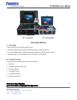
Packing List:
A - Fishfi nder 80 Sonar Unit (1)
B - Swivel Mount Bracket (1)
C - Swivel Base (1)
D - Mounting Knobs- Short (1), Long (1)
E - Mounting Knob Spacer (1)
F - Transducer With Power Cable (1)
G - Transducer Mount (1)
H - Trolling Motor Mount Gasket (1)
I - 5 mm Flat Washers (2)
J - 5 x 30 mm Screws (2)
K - 10-32 Lock Nut (1)
L - 4 x 12 mm Screws (4)
M - 10-32 x 1.75 Screw (1)
N - 1/4” Cable Clamps (2)
O - Plastic Spacer (1)
P - 1/4” Rubber Washer (1)
Q - Cable Tie, 5.6” (4)
R - Cable Tie, 20” (1)
S - Snap-Ring (1)
A
C
D
E
I
J
K
L
M
N
O
P
G
F
Q
H
R
B
(Cable not shown)
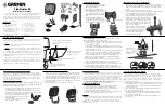
Assembling the Transducer
1. Insert the Rubber Washer and Plastic Spacer
in the transducer at the same time. DO NOT
lubricate the Rubber Washer.
2. Route the cable towards the back and
slide the transducer into the mounting bracket.
3. Place a 5 mm Flat Washer on the 10-32 x
1.75" screw and insert the screw through
the Mounting Bracket, Spacer and Rubber
Washer.
4. Place the remaining 5 mm Flat Washer on
the exposed end and install the 10-32
Lock Nut finger tight. The transducer will be
tightened further after installation on boat.
Mounting the Transducer On a Transom
Tool List (not included)
- Drill, 3/8" Wrench or Socket, 5/32" and 1/8" Drill Bits,
Masking Tape, #2 Phillips Screw Driver, Marine Sealant
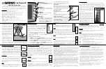
1. Position the transom mount at the selected location, making sure the transducer is
parallel with the water line. Mark the center locations of each hole on the transom
mount. (see figures to the right)
2. Using the 5/32" bit, drill the pilot holes approximately 1" (25 mm) deep at the
marked lo ca tions. To avoid drilling the holes too deep wrap a piece of tape around
the bit 1" from the point of the bit.
3. Apply Marine Sealant to the 5 x 30 mm screws. Attach the transducer to the transom
using the 5 x 30 mm screws. Adjust the transducer to extend beyond the bottom
of the transom approximately 1/8" (3 mm) on fiberglass hulls or 3/8" (10 mm) on
aluminum hulls. Adjust the transducer to be aligned parallel with the water.
5. Tighten the 10-32 locking nut until it touches the mounting bracket and then
tighten 1/4 turn more (do not overtighten).
6. Place the first cable clamp on the transducer cable approximately one third of the
distance between the transducer and the top of the transom. Mark the location.
Using a 1/8" bit, drill a pilot hole approximately 3/8" (10 mm) deep.
7. Attach the cable clamp using a 4 x 12 mm screw. Coat the screw with marine seal-
ant before installation. Repeat steps 6 and 7 using the other cable clamp.
8. Route the transducer cable as needed to the sonar unit. DO NOT CUT THE CABLE.
Try to avoid routing the cable with electrical wires or other sources of electrical
interference.
OK
Level
Drill Pilot Holes Here
V
ertical
Bottom of T
ransom
Align with transom
bottom. Transducer should
extend 1/8” below fiber-
glass hulls or 3/8” below
aluminum hulls.
Keep Parallel With Water Line
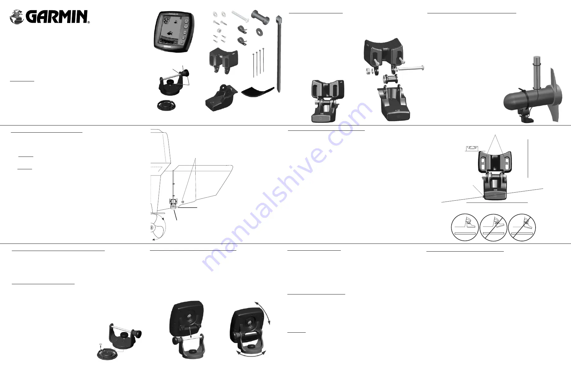
Installing the Unit On the Mounting Bracket
1. Align the slot on the back of the unit with the long mounting knob and slide in
place. It may be necessary to adjust the long knob to spread the bracket arms
apart. (Turn counter-clockwise to widen the bracket arms, clockwise to tighten.)
2. Adjust the unit angle and tighten the long mounting knob until snug.
3. Tilt the unit by loosening the long knob on the right side of the bracket assembly.
4. Rotate the entire bracket by twisting it left or right. (NOTE: You will hear clicks as
you turn the bracket.)
5. Tighten all knobs once the desired viewing angle is obtained.
Unit Installation — Selecting a Proper Location
Choose a location that provides optimal viewing while operating the vessel and
allows easy access to the unit’s keypad. Select a mounting surface strong enough to sup-
port the weight of the unit and protect it from excessive vibration or shock. DO NOT
mount the bracket in a location where the unit will be exposed to extreme tempera-
ture conditions. When installing the mounting bracket, be sure to allow room for the
connection/routing of the power cable.
Mounting the Bracket Assembly
Tool List (not included)
- Drill, Screwdriver (Phillips or Standard), three #8 pan head
machine bolts with matching nuts and washers and a 5/32” drill bit, OR three #8 pan
head self-tapping screws and a 1/16” drill bit
1. Using the swivel base as a template, mark the location of the three holes which
will be used to secure the bracket to the mounting surface.
2. If securing the base with machine bolts, drill three 5/32” holes at the locations
you marked. OR, If securing the base using self-tapping screws, drill 1/16” starter
holes at the locations you marked. Starter holes should
generally be no deeper than half the screw length.
3. Secure the swivel base with three bolts or screws. DO
NOT OVERTIGHTEN.
4. Place the rest of the mount over the swivel base
and secure with the short knob.
Wiring Harness Installation
The Fishfinder 80 comes with a wiring harness that connects the unit to power and
the transducer with one easy-to-remove connection. If it is necessary to extend the power
wires, use 22 AWG wire. DO NOT cut the transducer cable. This will void your warranty.
If your boat has an electrical system, it may be possible to wire the unit directly to an
unused holder on your current fuse block. If you are using the boat’s fuse block, remove
the in-line fuse holder supplied with the unit. You may also wire the unit direct to the bat-
tery.
CAUTION: The Fishfinder 80 input voltage is 10-18 volts DC.
DO NOT exceed
this voltage as this may damage the unit and void the warranty.
Installing the Wiring Harness:
1. Determine the polarity of the power source using a Test Light or Volt Meter.
2. Install the Red (+) wire on the Positive fuse holder or battery terminal.
3. Install the Black (-) wire on the Negative fuse holder or battery terminal.
4. Install a 2 amp fuse in the fuse holder (fuse block only).
5. Align the notches on the cable plug and back of the unit. Insert the cable into the
connector and turn the lock ring counter-clockwise unit it stops.
Unit Care
Cleaning -
Clean the unit housing using a cloth lightly dampened with a mild detergent
solution and then wipe dry. Avoid chemical cleaners and solvents that may damage plas-
tic components. Do not apply cleaner to electrical contacts on the back of the unit.
Storage -
Do not store the unit where exposure to temperature extremes may occur, as
permanent damage may result.
Do not mount the transducer behind strakes,
rivet lines, struts, fittings, water intakes or
discharge ports.
S