owner’s
manual
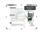
Fishfi nder 160
FF 160 updated covers.indd
08/07/00, 12:10 PM
1
www.reelschematic.com
Page 1: ...owner s manual Fishfinder 160 FF 160 updated covers indd 08 07 00 12 10 PM 1 www reelschematic com www reelschematic com...
Page 2: ...rage medium to be viewed for personal use provided that such electronic or printed copy of this manual contains the complete text of this copyright notice and provided further that any unauthorized co...
Page 3: ...ct registration system are now being automated and re registering your purchase ensures you the best possible support from GARMIN Customer Service Product Registration Thank You for choosing the GARMI...
Page 4: ...EVENT SHALL GARMIN BE LIABLE FOR ANY INCIDENTAL SPECIAL INDIRECT OR CONSEQUENTIAL DAMAGES WHETHER RESULTING FROM THE USE MISUSE OR INABILITY TO USE THIS PRODUCT OR FROM DEFECTS IN THE PRODUCT SOME STA...
Page 5: ...Hull w depth temp 010 10177 00 Bronze Thru Hull w depth temp speed 010 10119 00 Plastic Thru Hull w depth 010 10224 00 Plastic In Hull depth only 010 10249 00 Plastic Transom Mount w depth temp 010 10...
Page 6: ...lation 5 Wiring to a Fuse Block 5 6 Display Installation Surface Mount 7 Display Installation Flush Mount 8 Testing the Installation 9 Unit Operation 10 27 Using the Adjustment Bar Keypad Function 10...
Page 7: ...26 Memory Remember 27 Factory Setup 27 Software Version 27 On the Water 28 33 Understanding Sonar 28 Transducer Coverage 29 Understanding the Chart 30 Whiteline 31 Thermoclines 32 Simulator Mode 33 A...
Page 8: ...ducer or Speed Sensor the unit can display the boat s speed over water Fish The unit displays fish as arches or fish symbols and can alert you when a fish is detected Thermocline and Structure With GA...
Page 9: ...arge coverage area but at a decreased bottom resolution In deeper water this can result in a large dead zone where fish cannot be seen A narrow cone angle transducer is better suited to deep water ins...
Page 10: ...can cause cavitation that may degrade the boat s performance and damage the prop Make sure that the transducer is below water level when the boat is on plane at high speed Mount the transducer cable...
Page 11: ...transducer in the water pointed directly at the bottom and set unit for optimum performance Place the transducer in the test device as show on the side bar If the sonar performance is significantly d...
Page 12: ...ducer 3 Place the free end of the clamp band into the worm gear and tighten until the band is through the worm gear 4 Place the clamp and transducer over the body of the trolling motor Finish tighteni...
Page 13: ...ible to wire the unit directly to an unused holder on your current fuse block If you are using the boat s fuse block remove the in line fuse holder supplied with the unit Installing the Wiring Harness...
Page 14: ...connected to another piece of NMEA com patible electronic equipment If equipped with a capable transducer the Fishfinder 160 sends depth temperature and speed information that could be displayed on a...
Page 15: ...the four mounting holes with a pencil 3 Drill pilot holes for the mounting fasteners not included in kit 4 Secure the Surface Mount using the mounting fasteners 5 Slip the unit into the surface mount...
Page 16: ...W x 4 35 H relief hole where the unit will be mounted 3 Place the display in the relief hole and tape in place 4 Reinstall the knobs in the unit Install the surface mount with the cam lobes pointed t...
Page 17: ...bottom Verify that the unit is not in the simulator mode If the unit is in the simulator mode make sure that the transducer is connected to the wiring harness To test the transducer installation gradu...
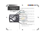
Page 18: ...ate Adjustment Bar and Setup Menu data fields for review or change Setup Key The Setup key is used to activate deactivate Setup Menu Power Key The Power Key is used to turn the unit on off and to acti...
Page 19: ...lay Messages and Alarm Icons are displayed along the bottom The Fishfinder 160 has three levels of display backlighting Off Low and High The backlight is activated by momentarily pressing the Power ke...
Page 20: ...to review the available settings before making a change press the ENTER key to activate the adjustment list Range The Range Adjustment is used to set the display depth range The unit can be set to aut...
Page 21: ...other than No Zoom is selected This setting allows you to select a specific area to view on the display or allow the unit to automatically select a viewing area based on the bottom To change the view...
Page 22: ...ty by selecting a higher gain If there is too much detail or if the screen is cluttered lowering the sensitivity may increase the clarity of the display To change the Gain 1 Highlight Gain on the Adju...
Page 23: ...access the Chart tab place the highlight over it using the arrow keys Fish Symbols Fish Symbols allows the user to determine how the chart will display underwater targets and background information If...
Page 24: ...e ON or OFF and press ENTER to accept the selection Scroll Speed The speed that the chart scrolls from right to left can be adjusted using the Scroll Speed selection field If you are sitting still or...
Page 25: ...verlay in the Corners with Basic or No Scale To Change the Scale Setting 1 Highlight the Chart tab on the Setup Menu 2 Highlight the Scale selection field and press ENTER 3 Choose Overlay Corners Basi...
Page 26: ...he arrow keys Depth Line When the Depth Line tool is activated a Depth Line selection is added to the Adjustment Bar To Activate the Depth Line 1 Highlight the Tools tab on the Setup Menu 2 Highlight...
Page 27: ...structure and bottom returns much the same as a true Flasher You may find this feature particularly useful when using Fish Symbols To Turn the Graphic Flasher On and Off 1 Highlight the Tools tab on...
Page 28: ...y Voltage and Speed fields on the chart To Select Normal or Large Numbers 1 Highlight the NUM tab on the Setup Menu 2 Highlight the Number Size selection field and press ENTER 3 Choose Normal or Large...
Page 29: ...re selection field and press ENTER 3 Choose Auto Show or Hide press ENTER to accept the selection Speed The Fishfinder 160 can display the boat s Speed Over Water when equipped with a speed capable tr...
Page 30: ...ER 3 Choose the desired setting press ENTER to accept the selection Shallow Water The Shallow Water Alarm can be set to sound a warning at a depth determined by the user Before the unit will sound a w...
Page 31: ...ng the arrow keys input the desired depth press ENTER to accept the setting Battery Voltage The Battery Voltage alarm can be set to warn you when the battery is reaching a critical state of discharge...
Page 32: ...s three settings Off Alarms Only and Key Alarm To Change the Beeper Setting 1 Highlight the System tab on the Setup Menu 2 Highlight the Beeper field and press ENTER 3 Choose Off Alarms or Key Alarms...
Page 33: ...field and press ENTER 3 Choose Fresh or Salt press ENTER to accept the selection Speed Sensor With a speed sensor installed the Calibrate Speed field will become available This will allow you to cali...
Page 34: ...renheit F or Celsius C To Select a Temperature Unit 1 Highlight the Units tab on the Setup Menu 2 Highlight the Temperature field and press ENTER 3 Select Fahrenheit or Celsius press ENTER to accept t...
Page 35: ...Setup Only press ENTER to accept the selection Factory Setup To Restore the Factory Settings 1 Highlight the Memory tab on the Setup Menu 2 Highlight the Factory Setup button and press ENTER 3 Choose...
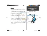
Page 36: ...ar demonstrates this showing an underwater scene as it would be displayed on the chart Generally speaking if the only thing between the transducer and the bottom is water the first strong return will...
Page 37: ...of the water depth As shown in Example 1 the coverage area at a 30 foot depth is approxi mately a 10 foot diameter circle The scale below illustrates how coverage increases as depth increases 1 10 9 8...
Page 38: ...art it appears the fish and tree are side by side but when we look at the scene from the top we can see that the fish is several feet from the tree It is important to remember that the fishfinder can...
Page 39: ...of the bottom type the black return makes this more difficult With the whiteline active the bottom return appears layered in shades of gray and black and makes determining the bottom type easier and...
Page 40: ...60 to see through thermoclines and helps locate fish where they live and fish love the thermocline A rough definition of a thermocline is a break in water where the water temperature changes faster th...
Page 41: ...of the chart While in the simulator mode the unit will display a random bottom scene and the Fishfinder 160 can be controlled just as if it were on the water The unit can be configured to act as if a...
Page 42: ...minutes Power Input 10 to 18 VDC with High Voltage Protect Usage 10 watts maximum Nominal 12 VDC 0 8 amps Performance Sonar Power Output 400 watts RMS 3200 watts peak to peak Frequency 200 kHz Depth...
Page 43: ...remove most messages after 10 seconds and display a reminder icon in the lower left corner of the chart until the alarm is no longer valid Battery Voltage Low Deep Water Alarm Shallow Water Alarm Sup...
Page 44: ...nd a suitable location for the transducer If you are in a slow moving boat such as a canoe or flat bottom boat the mounting location is not as critical Follow these simple guidelines and you should be...
Page 45: ...Installing the D Cell Batteries 1 Disconnect the Red and Black leads 2 Install the batteries noting the correct polarity 3 Reconnect the Red and Black leads and place the battery pack batteries down i...
Page 46: ...23 Battery Voltage display 20 Beeper 24 C Calibration 25 Chart 15 Contrast 24 D Deep Water 23 Depth 26 Depth Line 18 Display vi Display Installation 7 E Enter Key 10 F Factory Setup 27 Fish Alarm 22...
Page 47: ...anty i M Memory 27 Messages 35 N NMEA Output 24 Noise Reject 18 Number Size 20 Numbers 20 O Operation 28 P Portable Case 36 Power Key 10 R Range 12 Remember 27 S Scale 17 Scroll Speed 16 Setup Key 10...
Page 48: ...Contents vi Temperature 21 26 Testing the Installation 9 Tools 18 Transducers 1 Transom Mount Installation 2 Trolling Motor Installation 4 U Understanding Sonar 28 Units 26 V View 13 W Water Type 25...
Page 49: ...FF 160 updated covers indd 08 07 00 12 10 PM 3 www reelschematic com www reelschematic com...
Page 50: ...A GARMIN Europe Ltd Unit 5 The Quadrangle Abbey Park Industrial Estate Romsey SO51 9AQ U K GARMIN Asia Corporation No 68 Jangshu 2nd Road Shijr Taipei County Taiwan www garmin com Part Number 190 0015...