background image


190-00921-01 

March, 2009 

Revision A 


G300

Installation Manual


Summary of Contents for G300 for Cessna SkyCatcher

Page 1: ...190 00921 01 March 2009 Revision A G300 Installation Manual...

Page 2: ...to be viewed and to print one copy of this manual or of any revision hereto provided that such electronic or printed copy of this manual or revision must contain the complete text of this copyright no...

Page 3: ...and GDU 375 except where specifically noted INFORMATION SUBJECT TO EXPORT CONTROL LAWS This document may contain information which is subject to the Export Administration Regulations EAR issued by th...

Page 4: ...ion Considerations 2 4 2 6 Mounting Requirements 2 4 2 7 Unit Installation 2 4 2 8 Continued Airworthiness 2 4 3 GMU 44 3 1 3 1 Equipment Description 3 1 3 2 Electrical Specifications 3 1 3 3 Environm...

Page 5: ...Activation 8 1 8 1 Configuration Mode 8 1 8 2 Software Audio Data Identification 8 1 8 3 Software Loading Procedure 8 3 8 4 Configuration Procedure 8 6 8 5 Garmin Database Updates 8 7 8 6 XM Activati...

Page 6: ...nstallation 1 7 2 1 GDU 37X 2 1 2 2 GDU 37X Mounting Accessories 2 4 3 1 GMU 44 3 1 4 1 GSU 73 Unit View 4 1 4 2 GSU 73 Air Hose Fitting Locations 4 5 4 3 GSU 73 Orientation Calibration 4 6 5 1 GTP 59...

Page 7: ...B 4 1 GTP 59 O A T Probe Wiring Detail B 15 LIST OF TABLES TABLE PAGE 1 1 G300 LRU Part Numbers 1 3 1 2 G300 LRU Power Requirements 1 3 1 3 G300 LRU Physical Specifications 1 3 1 4 G300 LRU Environme...

Page 8: ...ation 5 2 7 1 SL40 Required Equipment 7 1 7 2 SL40 Installation Kit w Out Connectors 013 00121 20 7 1 7 3 SL40 Installation Kit D Sub 15 Pin 013 00121 30 7 1 7 4 SL40 Installation Kit RF Plug 013 0012...

Page 9: ...THER RESULTING FROM THE USE MISUSE OR INABILITY TO USE THIS PRODUCT OR FROM DEFECTS IN THE PRODUCT Some states do not allow the exclusion of incidental or consequential damages so the above limitation...

Page 10: ...WHETHER RESULTING FROM THE USE MISUSE OR INABILITY TO USE THIS PRODUCT OR FROM DEFECTS IN THE PRODUCT Some states do not allow the exclusion of incidental or consequential damages so the above limitat...

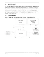
Page 11: ...ock diagram is given to aid in the understanding of the system This section also contains generic information that pertains to all components of the G300 system such as mounting wiring and antenna loc...

Page 12: ...panel or in a separate avionics bay if desired This design greatly eases troubleshooting and maintenance of the G300 system A failure or problem can be isolated to a particular LRU which can be repla...

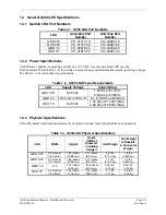
Page 13: ...ts LRU Supply Voltage Current Draw GDU 37X 9 29 Vdc 1 07 Amp 14Vdc 0 54 Amp 28Vdc GMU 44 12Vdc from GSU 73 Inc in GSU Current Draw GSU 73 9 29 Vdc 1 75 Amp 14Vdc Max 0 80 Amp 28Vdc Max 1 4 3 Physical...

Page 14: ...U 73 should be mounted in a location that provides adequate airflow to comply with the maximum outer case temperature listed in Section 4 NOTE Avoid installing the G300 LRUs near heat sources If this...

Page 15: ...ear aircraft control cables RG400 or RG142 coaxial cable with 50 nominal impedance and meeting applicable aviation regulations should be used for the installation Check that there is ample space for t...

Page 16: ...336 00022 01 Positronic P N 9502 5 M81969 1 04 for size 22D pins and M81969 1 02 for size 20 pins M22520 2 01 NOTES 1 Insertion Extraction tools from ITT Cannon are all plastic others are plastic wit...

Page 17: ...or the 50 62 and 78 pin connectors must be crimped onto the individual wires of the aircraft wiring harness Table 1 5 list contact part numbers for reference and recommended crimp tools 1 6 4 Backshel...

Page 18: ...tenna and DF receiver antenna is critical Use the following guidelines in addition to others in this document when locating the GDU 37X and its antennas GPS Antenna Locate as far as possible from all...

Page 19: ...1 Flight Instrument Functions Display of attitude pitch and roll rate of turn slip skid heading airspeed altitude and vertical speed information single display installation or on an MFD in reversionar...

Page 20: ...15W 1 10 Amp 9 5W 675 Amp 15W 0 540 Amp 9 25W 330 Amp 2 2 3 GPS Specifications The GDU 37X uses a WAAS enabled high sensitivity GPS receiver that continuously tracks and uses up to 12 satellites to c...

Page 21: ...X has an Operating Temperature Range of 20 C to 60 C 2 4 Installation Requirements 2 4 1 Required Accessories Each of the following accessories is provided separately from the GDU 37X unit and is requ...

Page 22: ...ate shield grounds at the backshell housing The instructions needed to install the Jackscrew Backshell 190 00313 11 and Configuration Module 190 00313 10 can be downloaded from the Dealer portion of t...

Page 23: ...ng life solid state sensing technology the GMU 44 Magnetometer uses magnetic field measurements to create an electronically stabilized AHRS The GMU 44 magnetometer provides magnetic information to sup...

Page 24: ...Considerations The following guidelines describe proper mechanical installation of the Garmin GMU 44 Magnetometer The guidelines include requirements for proper location selection in the aircraft requ...

Page 25: ...materials to mount the GMU 44 and replace any magnetic fasteners within 0 5 meter with nonmagnetic equivalents e g replace zinc plated steel screws used to mount wing covers or wingtips with nonmagne...

Page 26: ...me ground via the light assembly mounting 2 A dedicated power ground should be used and returned as a twisted pair with the power source back into the fuselage for a wing mounted GMU 44 These installa...

Page 27: ...onal 0 Parts used depend on method chosen 2 Shield Extension Wire 0 M22759 16 22 3 4 9 GMU 44 Connector Kit 1 011 00871 00 5 3 Conductor Cable 0 M27500 22TE3T14 6 2 Conductor Cable 0 M27500 22TE2T14 T...

Page 28: ...U 44 Place the connector at least 2 inches from the body of the GMU 44 to minimize this effect After attaching the GMU 44 s connector to its mate in the aircraft wiring secure the connector in place u...

Page 29: ...ng information and also computes OAT and TAS from inputs provided by the GTP 59 The GSU 73 is capable of maneuvers through a range of 360 in bank and pitch The rotation rate capability is 200 per seco...

Page 30: ...AHRS Engine Airframe Magnetic Heading 28 Analog inputs including those allocated as per below Pitch Angle Dedicated Ammeters 2 Roll Angle Constant Current Source Capability 6 Linear Accelerations Divi...

Page 31: ...450 Knots Aircraft Mach Range 1 00 Mach Aircraft Total Air Temperature Range 85 C to 85 C Unit Operating Temperature Range 40 C to 70 C Max Outer Case Temperature 73 C 4 4 Installation Requirements 4...

Page 32: ...appropriate aircraft fittings to connect to pitot and static system lines 4 5 Installation Considerations Fabrication of a wiring harness is required Sound mechanical and electrical methods and practi...

Page 33: ...for any flight condition Refer to part 43 Appendix E for approved practices while installing hoses and connections 4 5 2 Pneumatic Connections The installer is required to fabricate pneumatic hose con...

Page 34: ...in Figure 4 3 Figure 4 3 GSU 73 Orientation Calibration The GSU 73 includes an extremely sensitive strap down inertial measurement unit It must be mounted rigidly to the aircraft primary structure pr...

Page 35: ...t leveling and offset calibration procedure is not required Avoid placing the GSU 73 within 1 inch of magnetically mounted antennas speaker magnets or other strongly magnetic items 4 7 Unit Installati...

Page 36: ...Page 4 8 G300 Installation Manual GSU 73 Revision A 190 00921 01 This page intentionally left blank...

Page 37: ...wing part number Table 5 1 GTP 59 Part Number Item Garmin Part Number GTP 59 OAT Probe Kit 011 00978 00 5 2 Installation Requirements Table 5 2 contains a list of items found in the GTP 59 Outside Air...

Page 38: ...be incorrect if ice accumulates on the probe Furthermore computations dependent upon air temperature measurements may be affected e g true airspeed and delta ISA 5 3 2 GTP 59 OAT Probe Installation NO...

Page 39: ...probe Holding the OAT probe on the inside tighten the nut 5 to 100 inch lbs 20 inch lbs 3 Route the OAT probe cable 3 to the GSU 73 4 Cut the OAT Probe cable 3 to the required length Strip back 2 0 to...

Page 40: ...190 00921 01 5 4 Unit Installation Refer to Figure B 4 1 GTP 59 O A T Probe Wiring Detail for wiring and mounting instructions 5 5 Continued Airworthiness Maintenance of the GTP 59 is on condition onl...

Page 41: ...e GPS antenna 3 The GPS antenna should ideally be located at the opposite end of the aircraft from the COM unit in order to make the GPS less vulnerable to harmonics radiated from the COM itself 4a Th...

Page 42: ...Page 6 2 G300 Installation Manual Antennas Revision A 190 00921 01 Figure 6 1 below shows the recommended placement of antennas Figure 6 1 Recommended Antenna Placement...

Page 43: ...lane should be a conductive surface as large as practical with a minimum diameter of 8 inches To use an antenna in aircraft with fabric or composite skin a ground plane is recommended It is usually in...

Page 44: ...Page 6 4 G300 Installation Manual Antennas Revision A 190 00921 01 This page intentionally left blank...

Page 45: ...Installation Kit D Sub 15 Pin OEM 013 00121 30 1 SL40 Installation Kit RF Plug OEM 013 00121 40 1 Table 7 2 SL40 Installation Kit w Out Connectors 013 00121 20 Item Garmin P N Quantity Cable Tie 202 0...

Page 46: ...k 115 00431 00 1 Table 7 6 Contents of GTX 320 327 Connector Kit 011 00651 01 Item Garmin P N Quantity Nut Plate D Sub 25 Pos 125 00046 00 1 Screw 4 40x 500 FLHP100 SS P Nyl 211 63234 12 2 Tubing Ht S...

Page 47: ...To enter configuration mode hold down the left hand softkey while powering on the GDU 37X In a two display system hold down the left hand softkey on the PFD while powering on the unit 8 2 Software Aud...

Page 48: ...llowing steps to view the unit s current audio data information 1 Turn on the unit in normal mode 2 Press the ENT key twice to display the Main Menu 3 Use the FMS Joystick to select Database Informati...

Page 49: ...e Garmin folder or use the provided software update application 2 Copy all configuration ini files to the Garmin config folder 8 3 1 GDU Software Loading Procedure 1 Power on the GDU in normal mode th...

Page 50: ...rnal GDU memory If the current GSU software is different than the GSU software stored in GDU memory a GSU software update message will be displayed on the MESSAGES page The MESSAGES page is accessed b...

Page 51: ...921 01 Revision A 5 If the update is successful an UPDATE COMPLETE message appears press the ENT key to acknowledge the completion 6 An unsuccessful update is indicated by an UPDATE FAILED message Att...

Page 52: ...to select the FILE Page 1 Use the FMS Joystick to select Airframe if not already selected and press the ENT Key 2 Use the FMS Joystick to select Cessna 162 Baseline Configuration if not already select...

Page 53: ...patible PC computer Windows 2000 or XP recommended SanDisk SD Card Reader P Ns SDDR 93 or SDDR 99 or equivalent card reader Updated database obtained from the flyGarmin website SD Card 2 GB recommende...

Page 54: ...Basemap The basemap database contains data for the topography and land features such as rivers lakes and towns It is updated only periodically with no set schedule There is no expiration date Obstacle...

Page 55: ...to send an activation signal that allows the G300 MFD to display weather data and or entertainment programming XM service should activate in 45 to 60 minutes 1 The Radio ID can be displayed by access...

Page 56: ...Page 8 10 G300 Installation Manual Software Configuration Databases and XM Activation Revision A 190 00921 01 This page intentionally left blank...

Page 57: ...sitive state green check marks before performing any calibration procedures The GMU 44 and GSU 73 units must be communicating with the GDU 37X and the GPS antenna must have clear view of the sky or a...

Page 58: ...should have current calibration records Pitot static ramp tester Digital Multi Meter DMM Ground power unit capable of supplying 14 28 Vdc power to the aircraft systems and avionics Outdoor line of si...

Page 59: ...9 3 190 00921 01 Revision A Test the XM Receiver if applicable 1 Power on unit and use the FMS Joystick to select the XM Page 2 Verify that the XM receiver is functioning correctly as indicated by the...

Page 60: ...hich GMU 44 alignment is not within 0 5 of aircraft longitudinal axis E Engine Run Up Vibration Test Validate vibration characteristics of installation Procedure E is required for all installations F...

Page 61: ...the heading offset compensation The addition removal or modification of components that are ferrous or otherwise magnetic within 10 0 feet of the GMU 44 magnetometer location after the magnetometer in...

Page 62: ...indicate a positive state green check marks The GMU 44 and GSU 73 units must be communicating with the GDU 37X and the GPS antenna must have clear view of the sky or a GPS repeater to produce positive...

Page 63: ...rection of the GSU 73 connectors per the on screen instructions select OK and press the ENT Key to continue 10 After a few minutes the calibration will finish and a Done button will appear at the bott...

Page 64: ...e the FMS Joystick to select the GSU Page if needed 3 Unlock the GSU Page by pressing softkeys 2 3 4 in order if needed 4 Ensure that all three status boxes indicate a positive state green check marks...

Page 65: ...instructions 8 Use the FMS Joystick to highlight the Calibrate button at the bottom of the display press the ENT Key to begin the calibration 9 After a few minutes the calibration will finish and a Do...

Page 66: ...rcraft to a site that has been determined to be free of magnetic disturbances Ensure that there are no nearby magnetic materials on or near the perimeter of the site If unavoidable maneuver the aircra...

Page 67: ...that all three status boxes indicate a positive state green check marks The GMU 44 and GSU 73 units must be communicating with the GDU 37X and the GPS antenna must have clear view of the sky or a GPS...

Page 68: ...turn from the last heading the PFD instructs the operator to stop the aircraft NOTE Due to the difficulties in executing smooth accurate turns the PFD may incorrectly interpret a station and instruct...

Page 69: ...mum of 2 successful stations per quadrant is required where a successful station is a full 18 second countdown followed by instruction to move Ensure that if stations are skipped at least a minimum of...

Page 70: ...cockpit to precisely align the aircraft to cardinal compass heading reference lines on the compass rose In order to accomplish the necessary degree of accuracy in heading alignment it is generally req...

Page 71: ...button at the bottom of the display press the ENT Key to begin the calibration 9 The PFD display advises the operator when to turn the aircraft to a cardinal heading when to stop and when to turn to a...

Page 72: ...tion Procedures Revision A 190 00921 01 11 After the complete calibration is finished a Done button will appear at the bottom of the display ensure that a CALIBRATION SUCCESSFUL message appears at the...

Page 73: ...n mode by holding down the left hand softkey while powering on the GDU 37X if needed 2 Use the FMS Joystick to select the GSU Page if needed 3 Unlock the GSU Page by pressing softkeys 2 3 4 in order i...

Page 74: ...not pass after three attempts the installation should be considered unreliable until the source of the vibration problem is identified and remedied If the engine run up test fails repeatedly record th...

Page 75: ...f balance NOTE In some aircraft attempting the engine runup test on a day with very strong and or gusty winds may cause the test to occasionally fail However windy conditions should not be taken as ev...

Page 76: ...located in the same wing as a GMU 44 unit This procedure validates that no electronic device is interfering with the operation of the GMU 44 magnetometer which directly impacts the determination of at...

Page 77: ...190 00921 01 Revision A 5 Use the FMS Joystick to select MAGNETOMETER INTERFERENCE TEST 6 Use the FMS Joystick to highlight the Calibrate button press the ENT Key 7 Ensure that the aircraft has been p...

Page 78: ...erator should carry out the actions called for in the prepared test sequence NOTE It is important that all actions are carried out in the order and at the precise elapsed time as specified in the prep...

Page 79: ...usly 4 20 Beacon on 4 30 Beacon off 4 40 Pitot heat on 4 50 Pitot heat off 5 00 End of test If the test fails the installation should be considered unreliable until the source of magnetic interference...

Page 80: ...he pitch roll offset compensation procedure Procedure B However prior completion of the Magnetometer Calibration Procedure Procedure C is not required In order to evaluate a candidate site the Magneto...

Page 81: ...counter clockwise directions for the site to be considered acceptable More than one failure out of ten attempts in a given direction would be sufficient reason to conclude the site is not acceptable A...

Page 82: ...Page 9 26 G300 Installation Manual Post Installation Checkout and Calibration Procedures Revision A 190 00921 01 This page intentionally left blank...

Page 83: ...lity especially if there is more than one label on the card This is usually caused by the card sticking in the overlay opening not by the card sticking to the socket inside the unit Try another card w...

Page 84: ...is applied regardless of magnetic anomaly detection 3 The GDU may display Red X on the heading if the GSU 73 does not have GPS information or if it senses a magnetic anomaly 4 While a magnetic anomaly...

Page 85: ...id Valid Reversion No GPS Bad Good Good Valid Valid Valid Reversion No Mag Good Bad or anomaly Good Invalid Valid Valid Reversion No Mag No Air Good Bad or anomaly Bad Invalid Valid Valid Coast On Gyr...

Page 86: ...the problem occurred on the ground was it within 100 feet of a hanger using GPS repeaters 4 How long did the failure last Was it brief or sustained Was it repetitive in nature If it was repetitive abo...

Page 87: ...stallation Manual Troubleshooting Page 10 5 190 00921 01 Revision A Figure 10 2 Attitude Air Data and Engine Airframe Fail Indication Reversionary or Split Screen PFD Figure 10 3 Attitude Fail Indicat...

Page 88: ...librated message is displayed the AHRS and or Magnetometer calibration needs to be performed or the GSU 73 configuration module is inoperative 2 The external installation configuration parameters are...

Page 89: ...nd or OAT indications are dashed out as shown in Figure 10 5 NOTE TAS information can only be displayed at speeds greater than 20 Knots i e TAS is invalid when the aircraft is sitting still Figure 10...

Page 90: ...ouple reference or applicable thermocouple is defective Check the wiring and replace the configuration module or applicable thermocouple 6 Are there one or more temperatures that drop as the electrica...

Page 91: ...G300 Installation Manual Troubleshooting Page 10 9 190 00921 01 Revision A Figure 10 7 Attitude Heading Air Data and Engine Airframe Failure Reversionary or Split Screen PFD...

Page 92: ...a loose wire harness that is able to move around during flight This condition may cause the wire to pull on or vibrate the connector making intermittent connections 4 Ensure that the GSU 73 is mounted...

Page 93: ...the GSU Page config mode must indicate a positive state green check marks before performing any calibration procedures Section 9 The GMU 44 and GSU 73 units must be communicating with the GDU 37X and...

Page 94: ...Page 10 12 G300 Installation Manual Troubleshooting Revision A 190 00921 01 This page intentionally left blank...

Page 95: ...es If the correct software version is not installed update the displays to the current G300 system software available on the web No configuration is required as a long as the configuration module is s...

Page 96: ...s with new Garmin P N 211 60037 08 If original screws must be re used coat screw threads with Loctite 242 blue thread locking compound Garmin P N 291 00023 02 or equivalent Important Mounting screws m...

Page 97: ...RE 7 SPARE 8 SPARE 9 CDU SYSTEM ID PROGRAM 2 In 10 CDU SYSTEM ID PROGRAM 1 In 11 RS 422 OUT A Out 12 RS 422 OUT B Out 13 RS 232 OUT 3 Out 14 RS 232 IN 2 In 15 POWER GROUND 16 POWER GROUND 17 CONFIG MO...

Page 98: ...R 1 and AIRCRAFT POWER 2 are diode ORed to provide aircraft power redundancy Pin Name Connector Pin I O AIRCRAFT POWER 1 P3701 32 In AIRCRAFT POWER 2 P3701 31 In POWER GROUND P3701 15 POWER GROUND P37...

Page 99: ...I O RS 422 OUT A P3701 11 Out RS 422 OUT B P3701 12 Out A 1 4 3 CAN Bus This data bus conforms to the BOSCH standard for Controller Area Network 2 0 B This bus complies with ISO 11898 Pin Name Connec...

Page 100: ...01 1 Out MONO AUDIO OUT LO P3701 18 A 1 6 2 Stereo Audio Pin Name Connector Pin I O STEREO AUDIO OUT LEFT P3701 3 Out STEREO AUDIO OUT LO P3701 20 STEREO AUDIO OUT RIGHT P3701 19 Out STEREO AUDIO OUT...

Page 101: ...Power input pins accept 14 28 VDC AIRCRAFT POWER 2 is for connecting to an alternate power source such as on aircraft with two electrical buses Pin Name Connector Pin I O 12 VDC POWER GMU 44 P441 9 In...

Page 102: ...A 4 Rear Connector J731 Viewed from Connector End of Unit J731 pins are configured as shown in preceding figure J731 pin assignments are given in the following table additional tables group pin conne...

Page 103: ...2 A In 28 ARINC 429 IN 2 B In 29 CAN BUS TERMINATION 30 ARINC 429 IN 3 A In 31 ARINC 429 IN 3 B In 32 ARINC 429 IN 4 A In 33 ARINC 429 IN 4 B In 34 SIGNAL GROUND 35 SIGNAL GROUND 36 SIGNAL GROUND 37 S...

Page 104: ...ANALOG IN 6 LO In 14 ANALOG IN 12 LO In 15 OAT PROBE IN HI In 16 OAT PROBE POWER OUT Out 17 FREQUENCY COUNTER IN 1 In 18 SIGNAL GROUND 19 FREQUENCY COUNTER IN 2 In 20 CONFIG MODULE CLOCK Out 21 ANALO...

Page 105: ...T Out 56 TRANSDUCER POWER OUT LO GROUND 57 TRANSDUCER POWER OUT LO GROUND 58 10 VDC TRANSDUCER POWER OUT Out 59 CONFIG MODULE POWER OUT Out 60 ANALOG IN 4 HI In 61 ANALOG IN 1 HI In 62 ANALOG IN 10 HI...

Page 106: ...2 12VDC TRANSDUCER POWER OUT OUT 56 P732 TRANSDUCER POWER OUT LO GROUND 58 P732 10VDC TRANSDUCER POWER OUT OUT 57 P732 TRANSDUCER POWER OUT LO GROUND 75 P732 5VDC TRANSDUCER POWER OUT OUT 74 P732 TRAN...

Page 107: ...Pin Connector Pin Name I O 20 P731 ARINC 429 OUT 1A OUT 21 P731 ARINC 429 OUT 1B OUT 22 P731 ARINC 429 OUT 2A OUT 23 P731 ARINC 429 OUT 2B OUT 25 P731 ARINC 429 IN 1A IN 26 P731 ARINC 429 IN 1B IN 27...

Page 108: ...d of the bus Pin Connector Pin Name I O 7 P731 CAN BUS HI I O 8 P731 CAN BUS LO I O 29 P731 CAN BUS TERMINATION A 3 5 5 Configuration Module Interface Pin Connector Pin Name I O 20 P732 CONFIG MODULE...

Page 109: ...is achieved via software configuration When Disabled Hardware scaling is 1 1 and input impedance is greater than 10 M When Enabled Hardware scaling is approximately 45 1 and input impedance is approxi...

Page 110: ...I IN 13 P732 ANALOG IN 6 LO IN 63 P732 ANALOG IN 7 HI IN 43 P732 ANALOG IN 7 LO IN 23 P732 ANALOG IN 8 HI IN 3 P732 ANALOG IN 8 LO IN 24 P732 ANALOG IN 9 HI IN 4 P732 ANALOG IN 9 LO IN 62 P732 ANALOG...

Page 111: ...2 ANALOG CURRENT MONITOR IN 2 LO IN 10 P732 THERMOCOUPLE REF IN HI IN 9 P732 THERMOCOUPLE REF IN LO IN A 3 8 Temperature Inputs Temperature input is used for Outside Air Temperature OAT computations T...

Page 112: ...EQUENCY COUNTER IN 1 IN 19 P732 FREQUENCY COUNTER IN 2 IN 36 P732 FREQUENCY COUNTER IN 3 IN 38 P732 FREQUENCY COUNTER IN 4 IN Indicates Active Low The following table lists the minimum frequency maxim...

Page 113: ...198 8 6 04 153 4 2 98 75 8 3 89 98 7 2X 1 72 43 7 004 0 1 1 09 27 7 86 7 3 41 59 15 0 1 08 27 5 6 32 CAPTIVE SCREW 4 PLCS 5 47 139 1 7 25 184 2 3 41 86 7 28 7 2 29 7 3 93 23 7 2X 2 34 59 4 1 92 48 7...

Page 114: ...R 39 TYP 10 0 19 TYP 4 9 1 24 31 5 0 0 0 1 50 38 0 3 67 93 1 3 67 93 1 2X 3 58 91 1 2X 3 58 91 1 0 0 0 2 78 70 7 2X 2 69 68 4 2 78 70 7 2X 2 69 68 4 2 21 56 2 C L C L 011 01747 GDU 37x OUTLINE REF NO...

Page 115: ...FT MOUNTING INSTRUCTIONS OF THE GRS 77 AHRS AND GMU 44 MAGNETOMETER UNIT 3 FOLLOW FORWARD AND TOP INDICATIONS ON UNIT AND RACK 2 51 2 49 63 75 63 25 164 4 17 THRU IN THIN MATERIAL USING LOCKING NUTS O...

Page 116: ...n A 3 37 85 60 2 10 53 34 2 38 60 33 1 84 46 61 8 4 214 3 8 AIRCRAFT MOUNTING SURFACE NOTES 1 DIMENSIONS IN INCHES mm GMU 44 INSTALLATION FROM ABOVE PREFERRED GMU 44 AIRCRAFT MOUNTING RACK 6 32 100 FL...

Page 117: ...ion A GMU 44 6 32 100 FLAT HEAD BRASS SCREWS REQUIRED 6 32 PAN HEAD BRASS SCREWS 0 24 6 1 MAX THREAD LENGTH WITHOUT CLEARANCE HOLES AIRCRAFT MOUNTING RACK 2 23 56 52 2 38 60 33 8 4 214 3 370 85 60 3 8...

Page 118: ...NGS GMU 44 G300 Installation Manual Outline Installation Drawings Page B 11 Page B 12 blank 190 00921 01 Revision A NOTE 1 BUBBLE NUMBERS IN THIS DRAWING REFER TO REFERENCE NUMBERS LISTED IN TABLES 3...

Page 119: ...OCATION INCLUDES UNIT WITH CONNECTOR KITS 4 186 2 139 8 5 50 2X 2X 7 33 1 45 36 7 PITOT AIR FITTING 1 8 27 ANPT FEMALE THREAD 1 8 27 ANPT FEMALE THREAD P732 STATIC AIR FITTING P731 49 8 3 96 1 96 2X 1...

Page 120: ...27500 22TE3V14 CABLE LENGTHTO BE 10 FEET 6 INCHES 4 16 AWG WIRE M22759 16 16 LENGTH OF WIRE OUTSIDE OF CASE TO BE 3 5 INCHES 0 25 0 5 SOLDER TERMINAL MS25036 109 6 SHIELD OF CABLE ELECTRICALLY CONNECT...

Reviews: