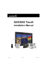
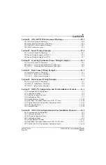
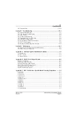
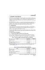
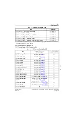
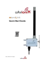
background image

190-01115-01

July, 2017

Revision AC

G3X/G3X Touch

Installation Manual

Summary of Contents for G3X Touch

Page 1: ...190 01115 01 July 2017 Revision AC G3X G3X Touch Installation Manual ...

Page 2: ...he KS 66062 USA Garmin Europe Ltd Liberty House Hounsdown Business Park Southampton Hampshire SO40 9LR U K Garmin aviation product support and warranty information can be found at www flygarmin com RECORD OF REVISIONS INFORMATION SUBJECT TO EXPORT CONTROL LAWS This document may contain information which is subject to the Export Administration Regulations EAR issued by the United States Department ...

Page 3: ... references 25 34 25 36 25 5 9 25 5 12 Added GP input info 25 57 25 13 2 Added note regarding GSU 25 power output 25 72 25 16 1 Corrected GTR 20 connector orientation 26 14 26 16 26 24 26 2 Updated Figure 26 2 2 p 4 Added Figure 26 2 4 for the GDL 5XR Updated Figure 26 2 11 and Figure 26 2 12 28 3 28 9 28 2 28 4 Updated Fig 28 2 1 and Figure 28 4 29 1 29 5 29 6 29 Updated Figure 29 1 Figure 29 2 2...

Page 4: ...the G3X system is not type certificated and is not suitable for installation in type certificated aircraft NOTE Unless otherwise noted all installation guidance requirements and instructions apply to one display two display three display and four display G3X systems NOTE References to the GDU 37X throughout this manual apply equally to the GDU 370 and GDU 375 except where specifically noted NOTE R...

Page 5: ... by the GMU 22 NOTE Connector references JXXX X and PXXX X are used throughout this document The letter J or P designates the connector whether on the LRU or wiring harness J Jack refers to the connector on the LRU and P Plug refers to the connector on the wiring harness J or P designate the connector only regardless of contact type pin or socket However GDU 4XX connectors on the LRU are designate...

Page 6: ... any interference including interference that may cause undesired operation of the device Cet appareil est conforme aux normes RSS sans licence d Industrie Canada Son fonctionnement est soumis aux conditions suivantes 1 cet appareil ne doit pas causer d interférences et 2 doit accepter toute interférence y compris les interférences pouvant entraîner un fonctionnement indésirable de l appareil NOTE...

Page 7: ...obal Positioning Service GPS Use of such devices may impair reception of GNSS signals THE WARRANTIES AND REMEDIES CONTAINED HEREIN ARE EXCLUSIVE AND IN LIEU OF ALL OTHER WARRANTIES WHETHER EXPRESS IMPLIED OR STATUTORY INCLUDING ANY LIABILITY ARISING UNDER ANY WARRANTY OF MERCHANTABILITY OR FITNESS FOR A PARTICULAR PURPOSE STATUTORY OR OTHERWISE THIS WARRANTY GIVES YOU SPECIFIC LEGAL RIGHTS WHICH M...

Page 8: ...anical Considerations 2 24 2 5 LRU Sensor Installation Information 2 27 Section 3 GAD 27 Flaps Lights Trim Controller Installation 3 1 3 1 Equipment Description 3 1 3 2 Equipment Available 3 3 3 3 General Specifications 3 3 3 4 Mounting Requirements 3 3 3 5 Unit Installation 3 3 3 6 Outline and Installation Drawings 3 4 Section 4 GAD 29 ARINC 429 Adapter Installation 4 1 4 1 Equipment Description ...

Page 9: ...ngs 7 5 Section 8 GDU 46X Display Unit Installation 8 1 8 1 Equipment Description 8 1 8 2 General Specifications 8 2 8 3 Installation Information 8 2 8 4 Unit Installation 8 3 8 5 Antennas 8 4 8 6 Mounting Requirements 8 4 8 7 Outline and Installation Drawings 8 5 Section 9 GDU 470 Display Unit Installation 9 1 9 1 Equipment Description 9 1 9 2 General Specifications 9 2 9 3 Installation Informati...

Page 10: ...2 Equipment Available 13 1 13 3 General Specifications 13 2 13 4 Mounting and Wiring Requirements 13 2 13 5 Outline and Installation Drawings 13 3 Section 14 GMU 11 Magnetometer Installation 14 1 14 1 Equipment Description 14 1 14 2 General Specifications 14 1 14 3 Equipment Available 14 2 14 4 Unit Installation 14 2 14 5 Outline and Installation Drawings 14 5 Section 15 GMU 22 Magnetometer Instal...

Page 11: ... 73 Sensor Unit Installation 19 1 19 1 Equipment Description 19 1 19 2 General Specifications 19 2 19 3 Required Equipment 19 3 19 4 Unit Installation 19 4 19 5 Outline and Installation Drawings 19 7 Section 20 GTP 59 Temperature Probe Installation 20 1 20 1 Equipment Description 20 1 20 2 General Specifications 20 2 20 3 Unit Installation 20 2 20 4 GTP 59 Icing 20 4 20 5 Outline and Installation ...

Page 12: ...tions 24 7 Section 25 LRU Pinouts 25 1 25 1 GAD 27 Flaps Lights Trim Controller 25 1 25 2 GAD 29 ARINC 429 Adapter 25 9 25 3 GDU 37X Display Unit 25 13 25 4 GDU 4XX Display Unit 25 18 25 5 GEA 24 EIS Interface 25 27 25 6 GI 260 AOA Indicator 25 42 25 7 GMC 305 AFCS Mode Controller 25 44 25 8 GMC 307 AFCS Mode Controller 25 46 25 9 GMU 11 Magnetometer 25 48 25 10 GMU 22 Magnetometer 25 49 25 11 GPS...

Page 13: ...SU 73 Rotax Sensor Drawings 31 5 Section 32 Jabiru Sensor Wiring Examples 32 1 32 1 Notes for Section 32 Drawings 32 1 32 2 GEA 24 Jabiru Sensor Drawings 32 2 32 3 GSU 73 Jabiru Sensor Drawings 32 4 Section 33 GDU 37X Configuration and Post Installation Checkout 33 1 33 1 Recommended Test Equipment 33 1 33 2 Configuration Mode 33 2 33 3 Software Loading Procedure 33 2 33 4 Configuration Pages 33 5...

Page 14: ...irworthiness Maintenance 36 1 36 2 Return to Service Information 36 4 Appendix A Airframe Specific Installation Guidance A 1 A 1 Introduction A 1 A 2 Van s Aircraft A 2 A 3 Lancair Aircraft A 5 Appendix B RS 232 Text Output Format B 1 B 1 Electrical Interface B 1 B 2 Message Output Selection B 1 B 3 General Message Output Format B 1 B 4 Attitude Air Data Message Format B 2 B 5 Engine Data Message ...

Page 15: ... a claim To justify a claim save the original shipping container and all packing materials Do not return any equipment to Garmin until the carrier has authorized the claim Retain the original shipping containers for storage If the original containers are not available a separate cardboard container should be prepared that is large enough to accommodate sufficient packing material to prevent moveme...

Page 16: ...ts LRU Connector Installation Kit Part Number Installation Kit Included with LRU GAD 27 Flaps Lights Trim Controller 011 03877 00 Table 3 2 N GAD 29 ARINC 429 Adapter 011 03271 00 Table 4 2 N GAP 26 Air Data Probe N A N GDU 37X Display 011 01921 00 Table 6 1 Y GDU 45X Display 010 12150 01 Table 7 1 N GDU 46X Display 010 12150 00 Table 8 1 N GDU 470 Display 010 12150 02 Table 9 1 N GDL 39R 9 Pin Co...

Page 17: ...41 00 Table 21 3 Y Garmin GPS and or XM Antennas NA N Table 1 5 Contents of GDL 39R Connector Kit 010 11825 20 Item Part Number Quantity Backshell w Hdw Jackscrew 9 15 pin 011 01855 00 1 Conn Receptacle d Sub Crimp Socket Commercial 9 CKT 330 00625 09 1 Contact Sckt Mil Crimp size 20 20 24 AWG 336 00022 02 9 Table 1 6 Contents of GDL 5XR Connector Kit 010 12498 60 Item Part Number Quantity Backshe...

Page 18: ...Probe Yes Section 5 GDL 39 GDL 39R Data Link No NA GDL 5XR Data Link No NA GDU 37X Display if installing more than one Yes Section 6 GDU 45X Display if installing more than one Yes Section 7 GDU 46X Display if installing more than one Yes Section 8 GDU 470 Display if installing more than one Yes Section 9 GEA 24 EIS Yes Section 10 GI 260 Yes Section 11 GMC 305 Mode Controller Yes Section 12 GMC 30...

Page 19: ...bject to change without notice Table 1 8 Pin Contact and Crimp Tools Part Numbers LRU Contact Type Garmin Contact Part Number Recommended Positioner Recommended Insertion Extraction Tool Recommended Hand Crimping Tool GDU 37X GDU 4XX Socket Size 20 336 00022 02 or 336 00094 00 M22520 2 08 Daniels K13 1 M81969 1 04 for size 22D pins and M81969 1 02 for size 20 pins M22520 2 01 GMC 305 307 Pin Size ...

Page 20: ...5 1 Section 34 5 1 and Section 35 3 1 for detailed information 1 5 6 Non Magnetic Tools Use of non magnetic tools e g beryllium copper or titanium is recommended when installing or servicing the GMU magnetometer Do not use a screwdriver that contains a magnet when installing or servicing a magnetometer 1 5 7 Pneumatic Hoses and Connectors Air hoses and fittings are required to connect pitot and st...

Page 21: ...n Garmin Equipment 1 7 1 Engine Airframe Sensors See Section 23 1 for a list of compatible sensors and Section 23 3 for a list of available sensor kits 1 7 2 Mounting Hardware Some sensors may require a torque screwdriver copper crush gasket 10 screws or 8 ring terminals for installation 1 8 Optional 3rd Party Sensors LRUs Refer to Section 29 Section 30 Section 31 and Section 32 for wiring configu...

Page 22: ... in order 1 Inventory of all needed parts 2 Planning layout of the installation 3 Installation of LRUs antennas and sensors 4 Construction of wiring harness cables and connectors 5 Software installation configuration 6 Post installation checkout procedure and calibration 2 1 System Overview The G3X is an advanced technology avionics suite designed to integrate pilot aircraft interaction into one c...

Page 23: ...centrator Optional GDU 375 PFD2 Optional GSU 25 ADAHRS 1 GDU 370 MFD Optional GSA 28 Roll Servo Optional GMC 305 307 A P Controller Optional GEA 24 Engine Analyzer GTX Transponder Optional No 2 GPS Com Optional No 1 GPS Com Optional GMA 240 Audio Panel Optional GARMIN COM OR NAV COM Optional Third party Autopilot Optional A429 Autopilot A429 NAV A429 GPS RS 232 A429 NAV RS 232 A429 GPS GAP 26 Pito...

Page 24: ...formation refer to Section 7 Section 8 and Section 9 GDU 4XX PFD1 GAD 29 Data Concentrator Optional GDU 4XX PFD2 Optional GSU 25 ADAHRS 1 GDU 4XX MFD1 Optional GMC 305 307 A P Controller Optional GEA 24 Engine Analyzer GTX Transponder Optional No 2 GPS Com Optional No 1 GPS Com Optional GARMIN COM OR NAV COM Optional Third party Autopilot Optional A429 Autopilot A429 NAV A429 GPS A429 NAV RS 232 A...

Page 25: ...ressure inputs for pitot static and angle of attack AOA For aircraft capable of indicated airspeeds greater than 300 knots the GSU 25B is used The GSU 25 communicates with other LRUs via the CAN bus and can optionally be connected to the PFD1 GDU via RS 232 for redundancy For GSU 25 installation information refer to Section 18 and Section 26 The older GSU 73 ADAHRS is also supported The GSU 73 doe...

Page 26: ... a separate heads up indication of AOA Refer to Section 11 for GI 260 installation information 2 1 1 7 Engine Information The G3X system includes highly flexible capabilities for monitoring numerous engine sensors and parameters and can support most piston and turbine engines including twin engine installations Airframe sensors such as voltage fuel quantity and discrete switch contact inputs are a...

Page 27: ...1 10 Navigation Basic VFR GPS navigation with the G3X system is performed by the GDU displays using their internal navigation databases in conjunction with GPS data from GDU GPS receivers or the GPS 20A Flight plan entry and modification is also performed via the GDU displays For VFR operations no other source of navigation data is required The G3X system also supports up to two external navigatio...

Page 28: ...ys or via their own front panel controls The GTR 20 is a remote mounted COM radio that is entirely controlled via the G3X Touch display with no front panel interface For GTR 20 installation information refer to Section 21 and Section 28 The interface between the G3X Touch system and the COM radio portion of a GTN GNC 255 or SL30 uses the same RS 232 connection described above for navigation data I...

Page 29: ... on traffic Section 2 1 1 16 and weather Section 2 1 1 15 interface capabilities For information on connecting and configuring a transponder with the G3X system refer to Section 26 and Section 33 or Section 34 Refer to Section 36 for information on performing periodic tests of the transponder 2 1 1 14 Autopilot The G3X system features an advanced digital flight director and autopilot based around ...

Page 30: ... These displays require a separate antenna connection and active XM subscription in order to receive satellite weather data For XM antenna installation information refer to Section 22 A G3X Touch system with GDU 4XX displays is also compatible with the GDL 51R SXM receiver and the GDL 52R dual ADS B SXM receiver The GDL 51R 52R connect to each GDU 4XX display via an RS 232 connection or wirelessly...

Page 31: ...upply in the event of alternator failure or during engine start Backup batteries designed for the G3X system are available from third party suppliers or a backup battery can be integrated into the aircraft s electrical system design in order to power additional devices In a G3X Touch system with GDU 4XX displays the GAD 27 electrical control system provides low voltage protection during engine sta...

Page 32: ...ELT The G3X system can provide NMEA 0183 formatted GPS position data to an ELT via an RS 232 output from a GDU display In an installation with a GTN GNS navigator an RS 232 output from the IFR GPS using the Aviation data format may be preferred For further ELT interface guidance consult the ELT manufacturer 2 1 1 22 Bluetooth The GDU 4XX displays in a G3X Touch system include Bluetooth transceiver...

Page 33: ...4 or 28 VDC except the GAD 27 which is 14 VDC only and the GAP 26 see Note in Section 5 Table 2 1 and Table 2 2 list supply voltage and current draw info for the G3X LRUs use this information when determining power supply requirements All installed electrical appliances must be considered when determining total power requirements 2 2 1 1 GAP 26 Power Requirements The 010 01074 00 version of the GA...

Page 34: ...p 28 Vdc 0 7 Amp GDU 46X 14 Vdc 2 0 Amp 28 Vdc 1 0 Amp GDU 470 14 Vdc 1 25 Amp 28 Vdc 0 7 Amp GEA 24 14 Vdc 0 43 Amp max typical external sensor loading 28 Vdc 0 21 Amp max typical external sensor loading GI 260 14 Vdc 0 4 Amp 28 Vdc 0 2 Amp GMC 305 14 Vdc 0 050 A 50 mA 28 Vdc 0 028 A 28 mA GMC 307 14 Vdc 0 120 A 120 mA 28 Vdc 0 067 A 67 mA GMU 11 14 28 Vdc 0 1 A 100 mA GMU 22 12 Vdc from GSU 25 G...

Page 35: ...t breaker Use MIL C 27500 or other approved cable for all shielded cable connections unless otherwise specified HSDB Ethernet connections may use either aviation grade Category 5 Ethernet cable or MIL C 27500 shielded twisted pair cable RG400 or RG142 coaxial cable with 50 Ω nominal impedance and meeting applicable aviation regulations should be used for the installation GSA 28 14 Vdc 0 36 Amp typ...

Page 36: ...le as far as possible away from all COM transceivers and antenna cables Analog Input wires routed too close to spark plugs plug wires or magnetos may result in erratic readings The installer shall supply and fabricate all of the cables Required connectors pins etc are provided with LRU Installation Kits Electrical connections for the GMU 22 are made through a round 9 pin connector and are made thr...

Page 37: ...nstalled in the connector backshell of the PFD1 display to store important configuration data Only the PFD1 display uses a configuration module in systems using a GSU 73 an additional configuration module is installed in the GSU 73 connector backshell See Section 24 for installation instructions Figure 2 3 Original Green Configuration Module P N 011 00979 20 Figure 2 4 shows the Apple iOS compatib...

Page 38: ...ed terminated at each end Figure 2 6 The overall length of the CAN bus from end to end should be 20 meters 66 feet or less At each of the two extreme ends of the CAN bus a 120 Ω resistor is installed to terminate the bus In the G3X system termination resistors are provided either within the LRUs themselves or via termination adapters that plug into an LRUs CAN connection see Section 2 3 1 3 3 Figu...

Page 39: ...me point Rather than splicing two or more stub node connections together the CAN bus should instead be daisy chained from one device to the next Figure 2 7 Figure 2 7 Node Connections The layout of the CAN bus must be a single linear backbone with exactly two distinct end points Figure 2 8 Other layouts such as star or Y arrangements must be avoided Similarly hub devices must not be used with the ...

Page 40: ...he GEA 24 GSU 25 GAD 29 GMU 11 GPS 20A and G5 installation kits provide a 9 pin termination adapter that provides termination when attached to the device s main connector The termination adapter contains a 120 Ω resistor that is connected between pins 1 and 2 Figure 2 11 The GDU 37X GDU 4XX GAD 27 and GSU 73 contain a 120 Ω resistor inside the unit that provides termination when the CAN LO pin is ...

Page 41: ...4 P3701 P3701 P4X01 4X01 P P271 1 P27 2 3 1 NOTE JUMPER BETWEEN PINS 3 4 REQUIRED NOTE JUMPER BETWEEN PINS 3 4 REQUIRED WHEN GSA 28 IS LOCATED AT END OF CAN BUS WHEN GSA 28 IS LOCATED AT END OF CAN BUS CAN_TERM_1 3 CAN_TERM_1 3 CAN_TERM_2 4 CAN_TERM_2 4 GSA 28 PITCH SERVO GSA 28 PITCH SERVO NOTE JUMPER BETWEEN PINS 25 26 REQUIRED NOTE JUMPER BETWEEN PINS 25 26 REQUIRED WHEN GTR 20 200 IS LOCATED A...

Page 42: ...e CAN bus should not be terminated Figure 2 16 Figure 2 15 Correct CAN Bus Termination Example Figure 2 16 Incorrect CAN Bus Termination Examples LRU LRU CORRECT CAN BUS TERMINATED AT EACH END OF BACKBONE LRU LRU LRU TERM TERM INCORRECT ONE OF THE TERMINATIONS IS NOT AT END OF BACKBONE LRU LRU LRU LRU LRU TERM TERM INCORRECT ONLY ONE END OF BACKBONE IS TERMINATED LRU LRU LRU LRU LRU TERM ...

Page 43: ...Avoid star and Y topologies and do not use a hub device see Figure 2 12 The overall length of the bus should not exceed 20 meters 66 feet Keep all stub node connections as short as practical The maximum length of any stub node connection is 0 3 meters 1 foot Avoid connecting more than one device to the CAN bus backbone at the same point Instead daisy chain the CAN bus backbone from one device to t...

Page 44: ...istance of 40 ohms or less indicates that too many terminations are installed 5 Verify that the CAN HI and CAN LO signals are not swapped shorted together or open circuited at any LRU connector 6 Verify that the CAN HI and CAN LO signals are not shorted to ground this can happen when shielded wire is installed incorrectly 7 Highlight each device on the configuration mode system information page Se...

Page 45: ...laps Lights Trim Controller 3 78 inches 96 01 mm 1 954 inches 49 63 mm no connector 3 569 inches 90 65 mm with connector 5 204 inches 132 18 mm no connector 6 533 inches 165 93 mm with connector 0 64 lbs 0 29 kg 0 97 lbs 0 44 kg GAD 29 ARINC 429 Adapter 6 10 inches 154 9 mm 1 48 inches 37 6 mm 3 23 inches 82 0 mm no connector 5 10 inches 129 4 mm w connector 5 54 inches 140 7 mm w connector and CA...

Page 46: ...4 60 lbs 2 09 kg 4 81 lbs 2 18 kg GDU 465 Display 10 85 inches 275 5 mm 7 82 inches 198 6 mm 3 57 inches 90 7 mm 4 73 lbs 2 15 kg 4 94 lbs 2 24 kg GDU 470 Display 6 01 inches 152 6 mm 7 82 inches 198 6 mm Depth behind panel including recommended backshell 3 68 inches 93 4 mm 2 66 lbs 1 21 kg 2 93 lbs 1 33 kg GEA 24 EIS 6 5 inches 165 1 mm 1 9 inches 48 3 mm 3 0 inches 76 2 mm 5 0 inches 127 0 mm w...

Page 47: ...nches 156 2 mm 1 28 inches 32 4 mm 8 80 inches 223 5 mm 10 22 inches 259 5 mm w connectors 1 19 lbs 0 540 kg 1 34 lbs 0 608 kg GTX 23ES Modular Rack 1 72 inches 44 mm Modular Rack 6 30 inches 160 mm 11 05 inches 281 mm Including Connectors measured from front face of unit to rear of connector backshells 3 1 lbs 1 41 kg Modular Rack Unit and Connectors 3 9 lbs 1 77 kg Remote Rack 1 78 inches 45 mm ...

Page 48: ...allation Information Each LRU sensor has unique considerations that the installer should be familiar with before beginning the physical installation Become familiar with all installation information by studying sections 3 18 of this document before actually beginning the installation of the LRUs sensors 2 5 1 External Navigator Connection Configuration External Navigators are connected LRUs that c...

Page 49: ...r The Flap Controller interfaces directly to the flap motor and uses flap position measured by the GEA 24 from an external position sensor to support up to 8 pre programmed flap settings The GAD 27 can automatically move the flaps between pre programmed positions in response to a momentary press of the flap control switch by the pilot Each momentary press of the flap switch causes the flaps to mov...

Page 50: ...a combined single interface to the trim motors or autopilot servos Switches used on pilot copilot control sticks do not supply trim motor power or control relays just provide ground to discrete inputs which improves switch reliability Discrete Inputs Provides 9 additional user configurable discrete inputs in addition to the 4 provided by the GEA 24 Lighting Bus Outputs One to three external panel ...

Page 51: ...thods and practices are recommended for installation of the GAD 27 Refer to Section 2 3 for wiring considerations and to Section 25 1 for pinouts 1 Mount the unit to a suitable mounting location using 4 10 32 pan or hex head screws 2 Assemble the connector backshells and wiring harness 3 Connect backshell connectors Table 3 1 GAD 27 Part Numbers Model Assembly Part Number Unit Only Part Number GAD...

Page 52: ...ne Drawing 3 780 96 01 5 204 132 18 100 2 54 040 1 02 TYPICAL THICKNESS BENEATH FASTENER HEAD 3 569 90 65 4 687 119 05 1 723 43 77 3 215 81 66 CENTER OF GRAVITY 984 24 99 CENTER OF GRAVITY 3 000 76 20 6 533 165 93 390 9 91 4 650 118 11 277 7 04 1 831 46 51 CENTER OF GRAVITY NOTES DIMENSIONS INCHES MM 1 DIMENSIONS ARE SHOWN FOR REFERENCE ONLY 2 ...

Page 53: ...ual GAD 27 Installation Rev AC Page 3 5 Figure 3 3 GAD 27 Installation Drawing J272 J271 P271 P272 TB273 011 01855 04 011 01855 01 330 00625 50 330 00625 15 GAD 27 011 03876 00 GAD 27 CONNECTOR KIT 011 03877 00 GAD 27 CONNECTOR KIT 011 03877 00 ...

Page 54: ...w 4 1 Equipment Description The GAD 29 allows the G3X system to interface to IFR navigators such as the GNS and GTN series The GAD 29 has a 25 pin D sub connector and a 9 pin D sub connector These connectors will provide the following functionality 2 Low Speed ARINC 429 Transmitters 4 Low Speed ARINC 429 Receivers 1 CAN Network Port NOTE A GAD 29 cannot be installed in a system that also includes ...

Page 55: ...cal methods and practices are recommended for installation of the GAD 29 Refer to Section 2 3 for wiring considerations and to Section 25 1 for pinouts 1 Mount the unit to a suitable mounting location using 4 10 32 pan or hex head screws 2 Assemble the connector backshells and wiring harness 3 Connect CAN terminator to unit if required Section 2 3 1 3 3 4 Connect backshell connectors Table 4 1 GAD...

Page 56: ... 352 59 74 2X 5 600 142 24 2X 250 6 35 2X 369 9 37 5 539 140 68 WITH CAN TERMINATOR 5 095 129 41 WITHOUT CAN TERMINATOR 5 095 129 41 2 950 74 93 CENTER OF GRAVITY 3 090 78 49 3 235 82 17 675 17 15 CENTER OF GRAVITY 2 350 59 69 CENTER OF GRAVITY NOTES DIMENSIONSIN INCHES mm METRIC VALUES ARE FOR REFERENCE ONLY 1 DIMENSIONS ARE NOMINAL AND TOLERANCES ARE NOT IMPLIED UNLESS SPEIFICALLY STATED 2 REFER...

Page 57: ...llation Manual GAD 29 Installation Rev AC Page 4 4 Figure 4 3 GAD 29 Installation Drawing no CAN terminator GAD 29 CONNECTOR KIT 011 03271 00 011 01855 02 330 00624 25 011 01855 00 330 00625 09 P291 P292 GAD 29 011 03236 00 J291 J292 ...

Page 58: ... 01855 00 011 01855 02 330 00625 09 330 00624 25 CAN TERMINATOR 011 02887 00 OPTIONAL IMPORTANT NOTE DEPENDING ON HOW THE SYSTEM IS PHYSICALLY WIRED THIS ADAPTER MAY OR MAY NOT BE NEEDED IN THE INSTALLATION THE G3X CAN BUS MUST BE TERMINATED AT ONLY THE TWO MOST EXTREME POINTS ON THE CAN BACKBONE REFER TO THE G3X INSTALL MANUAL FOR USAGE OF THIS PART AND SPECIFIC GUIDANCE OF THE G3X CAN BUS WIRING...

Page 59: ...All versions of the GAP 26 have identical aerodynamic performance including identical internal water separation baffling chambers drain holes pressure port locations and pneumatic tubing The 20 version of the GAP 26 includes a heater control box that is mounted separately from the probe Section 5 5 3 5 1 1 Moisture Protections Both pitot and AOA pressure chambers have internal baffling and dedicat...

Page 60: ...tion where airflow over the probe is relatively undisturbed typically mid wing span The tip of the GAP 26 should be located at least 4 from but not more than 10 below the bottom surface of the wing The probe tip may protrude up to 2 max in front of the leading edge of the wing Viewed from the side the GAP 26 probe bayonet centerline should be mounted within 5 from parallel to the wing chord line V...

Page 61: ...ter installation considerations Figure 5 2 GAP 26 Mounting Location Guidance 5 5 2 Heater Wiring Configuration The GAP 26 uses two internal heaters that may be powered by 14 or 28 volt systems Each of the heaters has two wires one of these two wires is banded Figure 5 3 to help identify individual heaters These heaters can be connected to a power source as shown in Figure 5 4 and Figure 5 5 Figure...

Page 62: ...4 GAP 26 14V Installation Configuration 010 01074 10 only Figure 5 5 GAP 26 28V Installation Configuration 010 01074 10 only NOTES FOR 14V INSTALLATION 1 AIRCRAFT POWER WIRING TO PROBE SHOULD BE MINIMUM 14 AWG UP TO 12 FT 12 AWG FROM 13 TO 20 FT AND 10 AWG FROM 21 TO 30 FT AC 43 13 1B NOTES FOR 28V INSTALLATION 1 CAUTION 28V INSTALLATIONS MUST FOLLOW THIS GUIDANCE AND CONNECT HEATERS IN SERIES AS ...

Page 63: ...are red and black heater wires from the control box should be connected to 14 VDC as shown in Figure 5 6 The bare blue wire from the control box can be run to a spare discrete input Section 5 5 4 Figure 5 6 011 02964 20 Probe Wiring Figure 5 7 011 02964 20 Probe to Control Box Connectors 20 VERSION GAP 26 20 VERSION GAP 26 HEATER CONTROL BOX HEATER CONTROL BOX BLACK WIRE BARE BLACK WIRE BARE BLACK...

Page 64: ...AOA pitot system However using it as a reference it specifies that the system shall be tested per the manufacturer s instructions but further states that if the manufacturer does not provide instructions the default test is to apply 150 knots pressure to the system and measure the pressure loss over one minute This loss is not to exceed 10 knots min While some GAP 26 probes will pass a test of thi...

Page 65: ...lation Drawings Figure 5 8 GAP 26 Outline Drawing 790 20 07 13 480 25 342 39 6 35 13 130 333 50 15 995 406 27 6 12 155 40 PITOT AOA 821 20 84 10 180 250 258 57 6 35 A A SECTION A A UNLESS OTHERWISE STATED INTERPRET PER ASME Y14 5M 1994 1 DIMENSIONS INCHES mm DIMENSIONS IN BRACKETS ARE FOR REFERENCE ONLY 2 ...

Page 66: ...Installation Manual GAP 26 Installation Rev AC Page 5 8 Figure 5 9 GAP 26 Heater Control Box used with 20 unit only 4X 150 THRU 0 250 389 2X 1 250 1 500 1 639 1 776 0 250 185 3 865 2X 4 050 4 300 2 320 960 0 618 575 1 110 450 960 ...

Page 67: ... a minimum of one GPS antenna is required for installations using more than one GDU 37X unit as the GDU 37X will share the GPS information with all GDU 37X units Additional GPS antennas may be used for redundancy but are not required The GDU 37X provides a central display and user interface for the G3X system The display is mounted flush to the aircraft instrument panel using four 6 captured screw...

Page 68: ...r devices Refer to Section 2 Section 26 Section 27 Section 28 and Section 33 for interconnect and configuration information 6 2 General Specifications See Section 2 2 for power current specifications and Section 2 4 1 for dimension weight specifications 6 3 Installation Information 6 3 1 Required Equipment Each of the following accessories is provided with the GDU 37X unit 010 00667 15 The connect...

Page 69: ...onfiguration module data against internal PFD memory and self configures to match the master system configuration module The PFD also maintains control of other LRUs configuration and calibration settings except for GSU 73 AHRS calibration settings which are stored in the GSU 73 configuration module This allows critical data to be retained with the airframe even if the PFD 1 display is replaced 6 ...

Page 70: ...lded cables a ground pin must be tied to the connector shell Figure 6 3 Figure 6 3 Grounded Connector Shell 6 5 Antennas Refer to Section 22 for antenna information NOTE GDU 37X units cannot be used with GA 35 GA 36 or GA 37 antennas 6 6 Mounting Requirements Refer to Section 6 7 for outline and installation drawings 6 6 1 Unit Installation The GDU 37X is installed by holding the unit flush with t...

Page 71: ... in 141 4 mm 7 33 in 186 2 mm Cut out panel to inside line For corner holes center punch and drill 36 tap 6 32 to create threaded holes OR drill out with 25 drill bit and use Garmin nut plate P N 115 01054 00 IMPORTANT Ensure the Page Scaling setting is set to NONE when printing this page Verify dimensions of printed template are accurate before cutting panel ...

Page 72: ...Outline Drawing 7 7 83 198 8 6 04 153 4 2 98 75 8 3 89 98 7 2X 1 72 43 7 004 0 1 1 09 27 7 86 7 3 41 59 15 0 1 08 27 5 6 32 CAPTIVE SCREW 4 PLCS 5 47 139 1 7 25 184 2 3 41 86 7 28 7 2 29 7 3 93 23 7 2X 2 34 59 4 1 92 48 7 4 50 114 4 XM CONN GPS CONN NOTES DIMENSIONS INCHES MM 1 DIMENSIONS ARE SHOWN FOR REFERENCE ONLY 2 FRONT SURFACE OF PANEL ...

Page 73: ...190 01115 01 G3X G3X Touch Installation Manual GDU 37X Installation Rev AC Page 6 7 Figure 6 6 GDU 37X Assembly Panel Cutout Drawing DIMENSIONS SHOWN FOR REFERENCE ONLY ...

Page 74: ...f one GPS antenna is required for installations using more than one GDU 4XX unit as the GDU 4XX will share the GPS information with all GDU 45X units Additional GPS antennas may be used for redundancy but are not required NOTE Make sure that no dust or grit accumulates at the bottom of the display glass The GDU 45X display uses invisible infrared beams for touch detection this makes it very import...

Page 75: ...ection 26 Section 27 Section 28 and Section 34 for interconnect and configuration information The GDU 45X supports video input via a wired connection see Section 25 4 4 The GDU 45X includes a wireless Bluetooth transceiver than can communicate with tablet computers and other Garmin devices that support the Connext interface protocol Refer to the G3X Touch Pilot s Guide 190 01754 00 for guidance in...

Page 76: ...e the GDU 45X to the panel as described in Section 7 6 1 Unit Installation and shown in Figure 7 4 7 4 Unit Installation Fabrication of a wiring harness is required Sound mechanical and electrical methods and practices are recommended for installation of the GDU 45X Refer to Section 2 3 for wiring considerations and to Section 25 4 for pinouts Connector kits include backshell assemblies Garmin s b...

Page 77: ...nit Installation The GDU 45X is installed by holding the unit flush with the instrument panel and fastening the four 3 32 hex socket head screws to the panel as shown in Figure 7 4 7 6 2 Panel Cutout Template The GDU 45X Nut Plate 115 01725 00 can be used as a template when marking the panel for cutout Figure 7 6 dimensions on the figure are to verify accuracy of printout only See Figure 7 5 for c...

Page 78: ...GDU 45X Outline Drawing 2X 2 13 54 2 4 32 109 7 FRONT SURFACE OF PANEL 58 14 7 10 3 41 38 7 1 52 1 68 42 6 7 5 30 87 22 2 2X 6 96 176 8 88 22 3 3X 42 3 1 66 2X 54 7 2 15 7 5 30 7 40 188 0 5 33 135 5 NOTES DIMENSIONS INCHES mm 1 DIMENSIONS ARE SHOWN FOR REFERENCE ONLY 2 FRONT SURFACE OF PANEL 2 70 68 6 3 68 93 4 7 99 203 0 5 93 150 5 ...

Page 79: ...190 01115 01 G3X G3X Touch Installation Manual GDU 45X Installation Rev AC Page 7 6 Figure 7 4 GDU 45X Assembly Drawing ...

Page 80: ... 45X Installation Rev AC Page 7 7 Figure 7 5 GDU 45X Panel Cutout Drawing not to scale 0 0 0 0 0 0 3 73 94 8 2X 3 77 95 7 3 73 94 8 2X 3 77 95 7 2 70 68 5 2X 2 73 69 4 2 70 68 5 2X 2 73 69 4 C L C L 7 46 189 5 5 39 137 0 4X R 29 7 4 4X 29 7 4 4X 29 7 4 ...

Page 81: ... 137 0 mm 5 39 in 5 39 in 189 5 mm 189 5 mm 7 46 in 7 46 in IMPORTANT Ensure the Page Scaling setting is set to NONE when printing this page Verify dimensions of printed template are accurate before cutting panel For corner holes center punch and drill 36 tap 6 32 to create threaded holes OR drill out with 25 drill bit and use Garmin nut plate P N 115 01725 00 The outline in this drawing is identi...

Page 82: ... TSO ETSO applicable to the GDU 46X NOTE Unless a GPS 20A is used for GPS position a minimum of one GPS antenna is required for installations using more than one GDU 4XX unit as the GDU 4XX will share the GPS information with all GDU 46X units Additional GPS antennas may be used for redundancy but are not required NOTE Make sure that no dust or grit accumulates at the bottom of the display glass T...

Page 83: ... 232 interfaces to communicate with Garmin LRUs and other devices Refer to sections Section 2 Section 26 Section 27 Section 28 and Section 34 for interconnect and configuration information The GDU 46X supports video input via a wired connection see Section 25 4 4 The GDU 46X includes a wireless Bluetooth transceiver than can communicate with tablet computers and other Garmin devices that support t...

Page 84: ...cure the GDU 46X to the panel as described in Section 8 6 1 Unit Installation and shown in Figure 8 4 8 4 Unit Installation Fabrication of a wiring harness is required Sound mechanical and electrical methods and practices are recommended for installation of the GDU 46X Refer to Section 2 3 for wiring considerations and to Section 25 4 for pinouts Connector kits include backshell assemblies Garmin ...

Page 85: ...nit Installation The GDU 46X is installed by holding the unit flush with the instrument panel and fastening the four 3 32 hex socket head screws to the panel as shown in Figure 8 4 8 6 2 Panel Cutout Template The GDU 46X Nut Plate 115 01725 01 can be used as a template when marking the panel for cutout Figure 8 6 dimensions on the figure are to verify accuracy of printout only See Figure 8 5 for c...

Page 86: ...ERENCE ONLY DIMENSIONS ARE SHOWN FOR REFERENCE ONLY 2 2 7 82 7 82 198 60 198 60 10 85 10 85 275 49 275 49 58 58 14 69 14 69 41 41 10 30 10 30 1 53 1 53 38 74 38 74 1 57 1 57 39 90 39 90 2 59 2 59 65 90 65 90 3 57 3 57 90 75 90 75 2 13 2 13 54 10 54 10 2X 2X 4 32 4 32 109 63 109 63 87 87 22 10 22 10 2X 2X 6 96 6 96 176 73 176 73 2 77 2 77 70 46 70 46 3X 3X 3 56 3 56 90 46 90 46 2X 2X 4 05 4 05 102 ...

Page 87: ...190 01115 01 G3X G3X Touch Installation Manual GDU 46X Installation Rev AC Page 8 6 Figure 8 4 GDU 46X Assembly Drawing ...

Page 88: ...4X 29 29 R7 35 R7 35 4X 4X 29 29 7 35 7 35 4X 29 29 7 35 7 35 4X 4X 7 29 7 29 185 10 185 10 10 31 10 31 262 00 262 00 00 00 0 93 45 93 45 3 68 3 68 2X 2X 3 64 3 64 92 55 92 55 3 64 3 64 92 55 92 55 3 68 3 68 93 45 93 45 2X 00 5 16 131 00 5 19 131 90 2X 5 19 131 90 2X 5 16 131 00 131 00 THIS DRAWING NOT TO SCALE THIS DRAWING NOT TO SCALE ...

Page 89: ...n 185 10 mm 185 10 mm 10 31 in 10 31 in 262 00 mm 262 00 mm IMPORTANT Ensure the Page Scaling setting is set to NONE when printing this page Verify dimensions of printed template are accurate before cutting panel Cut out panel to inside line For corner holes center punch and drill 36 tap 6 32 to create threaded holes OR drill out with 25 drill bit and use Garmin nut plate P N 115 01725 01 The outl...

Page 90: ...ion information Figure 9 1 GDU 470 Unit View 9 1 Equipment Description NOTE There is no TSO ETSO applicable to the GDU 470 NOTE Unless a GPS 20A is used for GPS position a minimum of one GPS antenna is required for installations using more than one GDU 4XX unit as the GDU 4XX will share the GPS information with all GDU 470 units Additional GPS antennas may be used for redundancy but are not requir...

Page 91: ...V radio 9 1 2 Interface Summary NOTE A G3X system installation can use either GDU 37X or GDU 4XX displays but a G3X system installation cannot use GDU 37X and GDU 4XX displays NOTE Please refer to the G3X Touch Pilot s Guide 190 01754 00 for guidance in using Connext Bluetooth connections to Garmin Pilot device s The GDU 470 uses CAN and RS 232 interfaces to communicate with Garmin LRUs and other ...

Page 92: ...ainst internal PFD memory and self configures to match the master system configuration module The PFD also maintains control of other LRUs configuration and calibration settings except for GSU 73 AHRS calibration settings which are stored in the GSU 73 configuration module the GSU 25 does not have a configuration module This allows critical data to be retained with the airframe even if the PFD 1 d...

Page 93: ...fastening the four 3 32 hex socket head screws to the panel as shown in Figure 9 4 9 6 2 Panel Cutout Template The GDU 470 Nut Plate 115 01725 03 can be used as a template when marking the panel for cutout Figure 9 6 dimensions on the figure are to verify accuracy of printout only See Figure 9 5 for complete cutout dimensions A dxf version of the drawing is also available for download at www garmi...

Page 94: ... 9 3 GDU 470 Outline Drawing 7 82 198 6 6 01 152 6 3 68 93 4 2 70 68 6 FRONT SURFACE OF PANEL 41 10 3 1 68 42 6 58 14 7 1 53 38 7 FRONT SURFACE OF PANEL 7 24 184 0 2 24 56 8 1 75 44 4 5 42 137 6 30 7 5 96 24 4 83 21 0 29 7 3 6 91 175 6 2X 2 09 53 0 4 27 108 6 NOTES 1 DIMENSIONS INCHES mm 2 DIMENSIONS ARE SHOWN FOR REFERENCE ONLY ...

Page 95: ...190 01115 01 G3X G3X Touch Installation Manual GDU 470 Installation Rev AC Page 9 6 Figure 9 4 GDU 470 Assembly Drawing ...

Page 96: ... 9 7 Figure 9 5 GDU 470 GDU 47X Nut Plate Drawing not to scale 5 48 139 1 7 30 185 5 0 0 0 3 65 92 8 2X 3 35 85 2 4X 29 7 4 4X 29 7 4 4X R 29 7 4 2X 3 31 84 0 3 65 92 8 2X 3 68 93 5 2X 3 68 93 5 0 0 0 2 74 69 6 2X 2 77 70 5 2X 2 89 73 4 2 74 69 6 2X 2 77 70 5 2X 2 89 73 4 C L C L ...

Page 97: ... 4 Cut out panel to inside line IMPORTANT Ensure the Page Scaling setting is set to NONE when printing this page Verify dimensions of printed template are accurate before cutting panel For corner holes center punch and drill 36 tap 6 32 to create threaded holes OR drill out with 25 drill bit and use Garmin nut plate P N 115 01725 03 The outline in this drawing is identical to the outline of the ac...

Page 98: ...th more than six cylinders The second GEA 24 must be configured as EIS 2 as described in Section 25 5 16 9 pin network power connector 50 pin miscellaneous connector for airframe sensors 25 pin thermocouple input connector 37 pin miscellaneous connector for airframe sensors will provide for the following input output functionality Configure analog digital and discrete I O capability Output digital...

Page 99: ...nly Part Number GEA 24 010 01042 00 011 02848 00 Table 10 2 Contents of GEA 24 Connector Kit 011 02886 00 Item Garmin P N Quantity Backshell w Hdw Jackscrew 9 15 Pin 011 01855 00 1 Backshell w Hdw Jackscrew 25 44 Pin 011 01855 02 1 Backshell w Hdw Jackscrew 37 62 Pin 011 01855 03 1 Backshell w Hdw Jackscrew 50 78 Pin 011 01855 04 1 CAN termination kit 011 02887 00 1 Conn Plug D Sub Crimp Pin Comme...

Page 100: ...provide an optional redundant path for engine data a secondary RS 232 connection to a single GDU display is also supported See Figure 26 1 9 for wiring and configuration information 1 Mount the unit to a suitable mounting location using 4 10 32 pan or hex head screws 2 Assemble the connector backshells and wiring harness 3 Connect CAN terminator to unit if required Section 2 3 1 3 3 4 Connect back...

Page 101: ... 6 80 172 7 0 04 1 TYPICAL THICKNESS BENEATH FASTENER HEAD 2X 6 40 162 6 2X 0 42 10 7 2 00 50 8 2X 0 20 5 1 3 4 86 CENTER OF GRAVITY 2 94 74 7 2 00 50 8 4 98 126 6 1 1 27 CENTER OF GRAVITY 0 2 4 CENTER OF GRAVITY NOTE 1 DIMENSION INCHES mm METRIC VALUES ARE FOR REFERENCE ONLY 2 DIMENSIONS ARE NOMINAL AND TOLERANCES ARE NOT IMPLIED UNLESS SPECIFICALLY STATED ...

Page 102: ...190 01115 01 G3X G3X Touch Installation Manual GEA 24 Installation Rev AC Page 10 5 Figure 10 3 GEA 24 Assembly Drawing no CAN terminator GEA 24 CONNECTOR KIT 011 02886 00 GEA 24 UNIT 011 02848 00 ...

Page 103: ...24 UNIT 011 02848 00 OPTIONAL GEA 24 CAN TERMINATION KIT 011 02887 00 IMPORTANT NOTE DEPENDING ON HOW THE SYSTEM IS PHYSICALLY WIRED THIS ADAPTER MAY OR MAY NOT BE NEEDED IN THE INSTALLATION THE G3X CAN BUS MUST BE TERMINATED AT ONLY THE TWO MOST EXTREME POINTS ON THE CAN BACKBONE REFER TO THE G3X INSTALL MANUAL FOR USAGE OF THIS PART AND SPECIFIC GUIDANCE OF G3X CAN BUS WIRING ...

Page 104: ...on The GI 260 is a remote mount Angle of Attack AOA indication The GI 260 has a pigtail harness for network communication and power connections 11 2 Equipment Available 11 2 1 Required Equipment 11 2 2 Additional Equipment Required The GI 260 Socket Mount 011 03562 00 is included with the unit The Socket Mount is secured using 3 6 32 100º flat head screws that are to be supplied by the installer T...

Page 105: ...rain wires 7 If applicable assemble the connector backshells and connect backshell connectors 11 5 Unit Calibration An in flight AOA calibration is required for GI 260 installations see Section 33 4 6 1 and Section 33 4 6 2 for GDU 37X installations or Section 34 4 7 1 and Section 34 4 7 2 for GDU 4XX installations 11 6 Unit Operation See Figure 11 2 for AOA display descriptions The GI 260 has two...

Page 106: ... G3X G3X Touch Installation Manual GI 260 Installation Rev AC Page 11 3 11 7 Outline and Installation Drawings Figure 11 3 GI 260 Outline Assembly Drawing GEA 24 CONNECTOR KIT 011 02886 00 GEA 24 UNIT 011 02848 00 ...

Page 107: ...Available 12 2 1 Required Equipment 12 2 2 Additional Equipment Required The following accessories are not provided with the GMC 305 unit The Installation Kit Table 12 2 is required to install the unit The Installation Kit includes the Connector Kit Table 12 3 and the Mounting Kit Table 12 4 Table 12 1 GMC 305 Part Numbers Model Assembly Part Number Unit Only Part Number GMC 305 010 01169 00 011 0...

Page 108: ...nut plates using flush mount rivets 3 Hold the unit flush with the instrument panel 4 Install the four mounting screws Installation Kit 010 12034 00 through the four mounting holes in the GMC 305 5 Use a 3 32 hex drive tool to turn each of the four mounting screws clockwise until tight 10 in lbs 12 4 4 Wiring The 15 pin connector pins and backshell supplied in the GMC 305 installation kit are used...

Page 109: ...e 12 2 GMC 305 Outline Drawing 46 11 6 TYP 86 21 8 84 0 3 31 1 27 32 2 5 34 135 6 1 24 1 69 31 4 13 0 51 34 8 6 42 9 080 2 03 TYP 1 85 47 0 6 25 158 8 2 1 DIMENSIONS ARE NOMINAL AND TOLERANCES ARE NOT IMPLIED UNLESS SPECIFICALLY STATED DIMENSIONS INCHES mm METRIC VALUES ARE FOR REFERENCE ONLY NOTES FRONT SURFACE OF AIRCRAFT PANEL ...

Page 110: ...C Page 12 4 Figure 12 3 GMC 305 Installation Drawing 011 03226 XX GMC 305 UNIT AIRCRAFT PANEL REF 4X 211 00169 01 SUPPLIED WITH 010 12034 00 INSTALLATION KIT CONNECTOR KIT SUPPLIED WITH 010 12034 00 INSTALLATION KIT 4X 210 00104 04 SUPPLIED WITH 010 12034 00 INSTALLATION KIT ...

Page 111: ...2X 660 16 76 865 21 97 925 23 50 2X 660 16 76 865 21 97 925 23 50 2 690 68 33 6X 2 860 72 64 72 64 6X 2 860 2 690 68 33 79 38 3 125 3 125 79 38 XXX 010 XX 0 25 XX 02 X 0 5 NOTES DIMENSIONS INCHES mm 1 TOLERANCES INCH mm 2 GMC 305 PANEL CUTOUT 5 54 4X 218 1 730 43 94 5 56 4X 219 5 380 136 65 4X R 065 1 65 MAX 150 4X 3 81 8X 098 THRU 176 4 47 X 100 ...

Page 112: ... CUT OUT PANEL TO INSIDE LINE IMPORTANT Ensure the Page Scaling setting is set to NONE when printing this page Verify dimensions of printed template are accurate before cutting panel 2 1 DIMENSIONS ARE NOMINAL AND TOLERANCES ARE NOT IMPLIED UNLESS DIMENSIONS INCHES mm METRIC VALUES ARE FOR REFERENCE ONLY NOTES SPECIFICALLY STATED GMC 305 PANEL CUTOUT ...

Page 113: ...trument panel using two pawl latches 13 2 Equipment Available 13 2 1 Required Equipment 13 2 2 Additional Equipment Required The following accessories are not provided with the GMC 307 unit The Installation Kit Table 13 2 is required to install the unit Table 13 1 GMC 307 Part Numbers Model Assembly Part Number Unit Only Part Number GMC 307 w Yaw Damper 010 01595 00 011 03993 00 GMC 307 no Yaw Dam...

Page 114: ...t panel 3 Using a 3 32 hex drive tool turn each of the two pawl latches clockwise until tightened to 20 2 in lbs When tightened the pawl latches are in the horizontal position Figure 13 2 Pawl Latch 13 4 3 Wiring The 15 pin connector pins and backshell supplied in the GMC 307 installation kit are used to add wiring for the GMC 307 It is recommended that a 2 Amp fuse or circuit breaker be used to s...

Page 115: ...E 3 10 2 C O G 40 C O G 3 29 83 6 NOTE 3 AIRCRAFT PANEL FRONT SURFACE OF NOTES DIMENSIONS INCHES mm METRIC VALUES ARE FOR REFERENCE ONLY 1 DIMENSIONS ARE NOMINAL AND TOLERANCES ARE NOT IMPLIED UNLESS SPECIFICALLY STATED 2 CENTER OF GRAVITY C O G LOCATION SHOWN IS WITHOUT CONNECTOR KIT INSTALLED 3 6 25 158 8 2 10 53 3 91 23 0 34 5 2 0 TYP 1 36 8 6 34 08 1 94 49 3 1 15 29 1 3 3 TYP 152 1 5 99 3 43 8...

Page 116: ...IMENSIONS INCHES mm 5 3 PAWL LATCH FASTENER INFORMATION NOTES THE PAWL LATCH FASTENERS WILL ACCOMMODATE PANEL THICKNESSES FROM 1 075 1 9 TO 140 3 6 THICK AND REQU THE FASTENERS ARE ENGAGED AND DISENGAGED BY USE OF A 3 32 HEX TOOL 2 TORQUE FASTENERS TO 20 2 IN LBS ON INSTALLATION AIRCRAFT PANEL 075 140 1 9 3 6 ALLOWABLE 011 01855 00 INCLUDED IN 011 01824 00 CONNECTOR KIT GMC 307 UNIT 011 03993 20 S...

Page 117: ...ation Rev AC Page 13 5 Figure 13 5 GMC 307 Cutout Drawing Not to Scale NOTES 1 DIMENSIONS INCHES mm METRIC VALUES ARE FOR REFERENCE ONLY 2 TOLERANCES INCH mm XX 02 X 0 5 XXX 010 XX 0 25 BEZEL OUTLINE REF 1 98 50 3 063 MAX 1 6 4X R 6 015 152 78 GMC 307 PANEL CUTOUT ...

Page 118: ...ONS INCHES mm METRIC VALUES ARE FOR REFERENCE ONLY 2 TOLERANCES INCH mm XX 02 X 0 5 XXX 010 XX 0 25 50 3 1 98 6 015 152 78 BEZEL OUTLINE REF IMPORTANT ENSURE THE PAGE SCALING SETTING IS SET TO NONE WHEN PRINTING THIS PAGE VERIFY DIMENSIONS OF PRINTED TEMPLATE ARE ACCURATE BEFORE CUTTING PANEL GMC 307 PANEL CUTOUT CUT OUT PANEL TO INSIDE LINE ...

Page 119: ...d a Directional Gyro to provide measurement of Roll Pitch and Heading angles The Garmin ADAHRS and magnetometer replace traditional rotating mass instruments Using long life solid state sensing technology the GMU 11 Magnetometer uses magnetic field measurements to create an electronically stabilized AHRS The GMU 11 magnetometer provides magnetic information to support the function of the ADAHRS GS...

Page 120: ...hen choosing a mounting location for the GMU 11 observe the following distances from objects or devices that can disturb the magnetic field Table 14 4 specifies recommended distances from magnetic disturbances for GMU 11 location NOTE If the requirements listed in Table 14 4 cannot be met a magnetometer interference test must be performed to ensure proper operation of the G3X system Refer to the A...

Page 121: ...ic materials and methods for rigid mounting of components is acceptable so long as adequate measures are taken to ensure a stiffened mounting structure Level the GMU 11 to within 3 0 of the in flight level cruise attitude Align the GMU 11 s forward direction to within 0 5 of the any of the 4 cardinal directions with relation between its connector and the nose of the aircraft Table 14 4 Recommended...

Page 122: ...lowing in the wing skin that encloses the GMU 11 Electrically isolating the light assembly should not be used as an alternative to the preceding consideration unless the isolated light assembly has been analyzed for adequate protection against direct attachment of lightning Refer to Section 14 5 for outline and installation drawings 14 4 2 Mounting Instructions After evaluation of the mounting loc...

Page 123: ...Installation Manual GMU 11 Installation Rev AC Page 14 5 14 5 Outline and Installation Drawings Figure 14 2 GMU 11 Outline Drawing 0 38 3 78 1 37 2 02 2 00 0 91 2 28 4 15 WITH CAN TERMINATOR 3 71 WITHOUT CAN TERMINATOR 0 93 2 74 ...

Page 124: ...11 04349 90 GMU 11 CONNECTOR KIT 500 THREAD LENGTH GMU 11 CONNECTOR KIT 6 FLAT WASHER SS 212 00024 06 SUPPLIED WITH 011 04349 90 6 32 PAN HEAD SS P SCREW 6 32 NUT HEX NYL LOCKING 316SS P 210 10008 08 SUPPLIED WITH 011 04349 90 GMU 11 CONNECTOR KIT 9 PIN CONNECTOR WITH OPTIONAL CAN TERMINATOR 011 03002 00 SUPPLIED WITH 011 04349 90 GMU 11 CONNECTOR KIT ...

Page 125: ... 73 to provide flight attitude and heading data for flight instrumentation An Attitude and Heading Reference System combines the functions of a Vertical Gyro and a Directional Gyro to provide measurement of Roll Pitch and Heading angles The Garmin ADAHRS and magnetometer replace traditional rotating mass instruments Using long life solid state sensing technology the GMU 22 Magnetometer uses magnet...

Page 126: ... the magnetic field Table 15 4 specifies recommended distances from magnetic disturbances for GMU 22 location NOTE If the requirements listed in Table 15 4 cannot be met a magnetometer interference test must be performed to ensure proper operation of the G3X system Refer to the AHRS Magnetometer Installation Considerations document 190 01051 00 available from the Garmin website www garmin com Tabl...

Page 127: ...g structure Level the GMU 22 mounting rack to within 3 0 of the in flight level cruise attitude Align the GMU 22 mounting rack s forward direction to within 0 5 of the longitudinal axis of the aircraft In a system with more than one ADAHRS GSU 25 73 ADAHRS 1 must be connected to a GMU22 but installing additional GMU 22 units for other GSU 25 ADAHRS units is optional An ADAHRS without a GMU 22 conn...

Page 128: ... Instructions Table 15 5 lists parts needed for the GMU 22 interconnect harness Some of the parts for installation are included in the GMU 22 Connector Installation Kit Other parts are provided by the installer Reference numbers refer to item bubble numbers shown in Figure 15 7 Table 15 6 lists material in the GMU 22 connector kit and the associated reference number as shown in Figure 15 7 The GMU...

Page 129: ...he GMU 22 to minimize this effect After attaching the GMU 22 s connector to its mate in the aircraft wiring secure the connector in place using good installation practices This will ensure that any remaining magnetic effect can be compensated for using the Magnetometer Calibration Section 33 4 4 3 for GDU 37X systems and Section 33 4 4 3 for GDU 4XX systems See Figure 15 2 for minimum recommended ...

Page 130: ... GMU 22 MOUNTING RACK 115 00481 00 NOTE 1 DIMENSIONS INCHES mm METRIC VALUES ARE FOR REFERENCE ONLY 2 FOLLOW FORWARD AND TOP INDICATIONS ON UNIT AND RACK 2 520 64 01 3 370 85 60 AIRCRAFT MOUNTING HOLES FOR 115 00481 00 FORWARD 2 51 2 49 63 75 63 25 3X 164 4 17 THRU IN THIN MATERIAL USING LOCKING NUTS OR DRILL AND TAP 6 32 UNC IN MATERIAL THICKER THAN 3 16 4 8 3X 213 5 41 OPTIONAL CLEARANCE HOLES F...

Page 131: ...190 01115 01 G3X G3X Touch Installation Manual GMU 22 Installation Rev AC Page 15 7 Figure 15 4 GMU 22 Mounting Rack 115 00481 10 ...

Page 132: ...HES mm METRIC VALUES ARE FOR DIMENSIONS ARE NOMINAL AND TOLERANCES ARE 1 2 REFERENCE ONLY NOT IMPLIED UNLESS SPECIFICALLY STATED NOTES GMU 22 INSTALLATION FROM ABOVE PREFERRED REQUIRED GMU 22 HEAD BRASS SCREWS 6 32 100 FLAT 00 IS SHOWN 115 00481 00 OR MOUNTING RACK AIRCRAFT 115 00481 10 6 32 PAN HEAD BRASS SCREWS 0 24 6 1 MAX THREAD LENGTH WITHOUT CLEARANCE HOLES 211 60037 08 SUPPLIED WITH 011 008...

Page 133: ...THREAD LENGTH WITHOUT CLEARANCE HOLES 211 60037 08 SUPPLIED WITH 011 00871 00 GMU 22 CONNECTOR KIT 115 00481 00 OR 115 00481 10 AIRCRAFT MOUNTING RACK 00 IS SHOWN AIRCRAFT MOUNTING SURFACE 2 23 56 52 2 38 60 33 16 2 412 3 370 85 60 GMU 22 INSTALLATION FROM BELOW NOT PREFERRED NOTES DIMENSIONS INCHES mm METRIC VALUES ARE FOR 1 REFERENCE ONLY DIMENSIONS ARE NOMINAL AND TOLERANCES ARE 2 NOT IMPLIED U...

Page 134: ...115 01 G3X G3X Touch Installation Manual GMU 22 Installation Rev AC Page 15 10 Figure 15 7 GMU 22 Wiring Details NOTE 1 BUBBLE NUMBERS IN THIS DRAWING REFER TO REFERENCE NUMBERS LISTED IN TABLES 13 5 AND 13 6 ...

Page 135: ...e GPS 20A provides an ADS B Out position source The WAAS SBAS position information is compatible with a wide range of 1090 ES transponders to meet the position requirements of 14 CFR 91 227 The GPS 20A also provides position data to all G3X and G3X Touch displays NOTE If a GPS 20A and connected GA 35 GA 36 or GA 37 antenna is used for GPS position additional GPS antennas connected to GDU 37X 4XX u...

Page 136: ...Mode S ADS B Out transponder meeting the requirements of TSO C166b and installed in accordance with the instructions in this document Example transponders which may be used in combination with the GPS 20A for FAR 91 227 compliance are the Garmin GTX 330ES GTX 23ES GTX 35R GTX 45R GTX 345 345R and GTX 335 335R 16 3 Equipment Available 16 3 1 Required Equipment Table 16 1 GPS Status LED Indications ...

Page 137: ...ness 3 Connect CAN terminator to unit if required Section 2 3 1 3 3 4 Connect backshell connectors 16 7 Antennas The GPS 20A requires the installation and use of a GA 35 GA 36 GA 37 or equivalent GPS WAAS antenna Refer to Section 22 for antenna information 16 8 Antenna Cable Requirements Cable loss from the GPS SBAS antenna should be between 1 5 dB and 6 5 dB in order to maintain proper rejection ...

Page 138: ... 01115 01 G3X G3X Touch Installation Manual GPS 20A Installation Rev AC Page 16 4 16 9 Outline and Installation Drawings Figure 16 2 GPS 20A Outline Drawing 5 064 135 1 759 3 488 2 250 4 600 2 800 275 232 ...

Page 139: ...G3X Touch Installation Manual GPS 20A Installation Rev AC Page 16 5 Figure 16 3 GPS 20A Installation Drawing no CAN terminator 011 01855 00 011 03913 00 J201 GPS 20A 330 00625 09 P201 GPS 20A CONNECTOR KIT 011 03914 00 ...

Page 140: ...HIS PART AND FOR SPECIFIC GUIDANCE OF THE G3X CAN BUS WIRING CAN TERMINATOR 011 02887 00 011 03913 00 330 00625 09 OPTIONAL IMPORTANT NOTE THIS ADAPTER MAY OR MAY NOT BE NEEDED IN THE INSTALLATION DEPENDENT UPON HOW THE SYSTEM IS PHYSICALLY WIRED THE G3X CAN BUS MUST BE TERMINATED AT ONLY THE TWO MOST EXTREME ENDS OF THE CAN BUS REFER TO SECTION 2 FOR GPS 20A CONNECTOR KIT 011 03914 00 ...

Page 141: ...ll autopilot with yaw damper The GSA 28 servo features an advanced brushless DC motor and gearbox with an engagement clutch to allow for very low friction operation of the aircraft flight controls with clutch disengaged The GSA 28 performs continuous internal monitoring and fault detection and can also safely be back driven by the pilot in the event of an engagement clutch fault condition An advan...

Page 142: ...auto trim functionality interfere NOTE Ensure basic autopilot functionality is properly adjusted before enabling trim control for any servo 17 1 1 Status LED The GSA 28 has an LED on its outer case that indicates its current status See Section 35 1 1 for details 17 2 Equipment Available 17 3 General Specifications 17 3 1 Power Specifications The trim outputs are capable of sourcing a maximum of 1 ...

Page 143: ...ations 14 Vdc without Auto trim 0 36 Amp typical 1 80 Amp max 28 Vdc without Auto trim 0 20 Amp typical 1 00 Amp max 14 Vdc with Auto trim 0 36 Amp typical 2 80 Amp max Table 17 4 GSA 28 Torque Specifications Characteristic Specification Maximum Rated Torque 60 in lbs Table 17 3 GSA 28 Power Specifications ...

Page 144: ...A 28 Mounting Kit RV 4 8 Pitch 011 02952 11 0 51 lb 0 231 kg GSA 28 Mounting Kit RV 7 8 10 Roll 011 02952 12 0 42 lb 0 191 kg GSA 28 Mounting Kit RV 9 Roll 011 02952 13 0 42 lb 0 191 kg GSA 28 Mounting Kit RV 6 7 9 Pitch 011 02952 14 0 37 lb 0 168 kg GSA 28 Mounting Kit RV 10 Pitch 011 02952 15 0 48 lb 0 218 kg GSA 28 Mounting Kit RV 10 Yaw 011 02952 16 0 60 lb 0 272 kg GSA 28 Removal Adapter 011 ...

Page 145: ...inding or interference is detected during installation or preflight inspection it must be corrected before flight CAUTION Do not mount the GSA 28 on the hot side engine side of the firewall or in any location where it would be exposed to radiated heat from the engine 17 5 2 1 Optional attachments The GSA 28 is supplied from the factory with a standard crank arm attachment Figure 17 2 Figure 17 8 1...

Page 146: ...racket should be positioned such that the stop bracket flanges are as close as practical to being equal distance from the servo s control arm while at the center of travel Also to prevent an over center condition the servo s push rod should be as close as practical to perpendicular with the servo s control arm while positioned at the center of travel The position of this bracket can be adjusted in...

Page 147: ...apply a small amount of thread locking compound to the threads of the stop bracket screws before the screws are inserted Thread locking compound is not required upon initial installation of the included stop bracket screws which are supplied with thread locking compound already applied 17 5 2 3 Trim Motor Interface The GSA 28 provides an optional interface between the pilot s electric trim switch ...

Page 148: ...o quickly disconnect the autopilot under all circumstances 17 5 2 5 GSA 28 Removal Adapter The GSA 28 connector kit is shipped with a GSA 28 removal adapter 011 03158 00 This part is not intended to be installed with the GSA 28 but is used to replace the GSA 28 when the harness connector is un plugged The removal adapter contains an internal 120Ω resistor between pins 2 and 3 for CAN termination I...

Page 149: ...190 01115 01 G3X G3X Touch Installation Manual GSA 28 Installation Rev AC Page 17 9 Figure 17 3 Wiring Diagram For GSA 28 Removal Adapter ...

Page 150: ...ncluded Install Manual Figures 011 02952 00 Sub Assy GSA 28 Mounting Kit Generic Push Pull No 17 8 7 011 02952 01 Sub Assy GSA 28 Mounting Kit Generic W Bracket Yes 17 8 8 011 02952 02 Sub Assy GSA 28 Mounting Kit Generic Capstan No 17 8 4 011 02952 10 Sub Assy GSA 28 Mounting Kit RV 6 Roll Yes 17 9 1 17 9 1 17 9 1 011 02952 11 Sub Assy GSA 28 Mounting Kit RV 4 8 Pitch Yes 17 10 1 17 10 1 17 10 1 ...

Page 151: ...ntire thread of the rod end bearing minus the jam nut The length of the push rod is adjustable by changing the thread engagement between the male rod end bearings and push rod The acceptable range of thread engagement is 0 492 0 117 It is highly recommended the AN315 3R jam nuts are used and properly tightened A push rod without a tightened jam nut will create backlash that can diminish autopilot ...

Page 152: ...The required bridle cable Figure 17 5 is a 1 16 cable with a MS20663C2 ball and double shank fitting swaged onto the cable where it engages with the capstan drive wheel The MS20664C2 ball and shank fittings on the ends keep the cable from fraying Several companies sell custom made cable assemblies suitable for this application a few of these are McFarlane Aviation Aircraft Spruce Phone 866 920 274...

Page 153: ...g the cable guard The screws provided are 0 25 long This length of screw is appropriate if there is no bracket or spacers in between the cable guard and servo If a mounting bracket or spacers of thickness 056 or greater will be place in between the stop bracket and servo longer screws should be used to attach the cable guard It is recommended the thread engagement into the GSA 28 as measured from ...

Page 154: ... thread engagement length is provided on the drawings for each kit The lengths specified are considered nominal This length should be adjusted to fit the specific application Ideal push rod length results in the push rod being perpendicular to the servo arm when it is at the center of travel It is recommended the stop bracket is installed with all push pull applications The drawings for each of th...

Page 155: ...laps the bushing protrusion when tightening down the mounting bolts The damage can occur when the bushing is displaced into the unit To prevent damage ensure there is clearance for the bushing protrusion and be sure the GSA 28 mounting plate is flush with the bracket when the mounting bolts are being tightened For RV 7 8 9 10 roll installations the rear support bracket used with other popular serv...

Page 156: ...190 01115 01 G3X G3X Touch Installation Manual GSA 28 Installation Rev AC Page 17 16 Figure 17 7 Non Garmin GSA 28 Bracket ...

Page 157: ...inal installation and assembly refer to the outline and installation drawings Figure 17 8 1 through Figure 17 14 1 17 6 Unit Wiring Refer to the Section 26 1 7 interconnect drawing for connecting GSA 28 wiring 17 7 Outline and Installation Drawings Refer to the following figures for GSA 28 installation guidance ...

Page 158: ...anual GSA 28 Installation Rev AC Page 17 18 Figure 17 8 1 GSA 28 Outline Installation Drawing 011 02927 00 CENTER OF SEE NOTE 5 A MOUNTING FLANGE THICKNESS CENTER OF SEE NOTE 5 CENTER OF SEE NOTE 5 LED STATUS LIGHT P281 DETAIL A GSA28 STANDARD ...

Page 159: ...e 17 19 Figure 17 8 2 GSA 28 Accessory Installation Drawing STOP BRACKET GSA28 STOP BRACKET KIT 011 02951 00 SEE NOTE 1 GSA28 UNIT D SUB CONNECTOR BACKSHELL GSA28 CONNECTOR KIT 011 02950 00 50 GSA28 STANDARD ACCESSORIES ITEMS INCLUDED IN 011 02950 00 DESCRIPTION 1 011 01855 01 1 ...

Page 160: ...RM A B C C B A SEE NOTE 1 SEE NOTE 1 SEE NOTE 9 SEE NOTE 8 PUSH ROD SEE NOTE 2 LONG CRANK ARM STOP BRACKET GSA28 CRANK ARM ATTACHMENTS BEARING ON OPPOSITE SIDE OF CRANK ARM AND AIRCRAFT ATTACHMENT RECOMMENDED ANGLE BETWEEN PUSH ROD AND CRANK ARM IS 90 AT MINIMUM THREAD ENGAGEMENT BETWEEN ROD END BEARINGS AND STOP BRACKET CAN BE RE POSITIONED IN INCREMENTS OF 15 ...

Page 161: ...2 2 5 CABLE GUARD CAN BE ROTATED TO ALLOW FOR ALTERNATE BOTH CABLES EXITING CAPSTAN IN SAME DIRECTION ROTATE A MAXIMUM OF 150 EITHER DIRECTION FROM BALL CABLE EXITING IN OPPOSITE DIRECTION SHOULD BE IN CENTER OF CABLE WRAP WHEN IN EITHER BALL FRONT OF FLANGE TO CENTER OF BALL PITCH NOMINAL ACCEPTABLE RANGE NOMINAL ACCEPTABLE RANG ITEMS INCLUDED IN 011 02952 02 ITEM DESCRIPTION 1 1 2 1 GSA28 CABLE ...

Page 162: ...G3X Touch Installation Manual GSA 28 Installation Rev AC Page 17 22 Figure 17 8 5 GSA 28 Recommended Bracket Cutout Dimensions M A M M A L A RECOMMENDED BRACKET CUTOUT DIMENSIONS BACK PANEL MOUNTING FRONT PANEL MOUNTING ...

Page 163: ...stallation Rev AC Page 17 23 Figure 17 8 6 GSA 28 Recommended Mounting Hardware SEE NOTE 2 EXAMPLE MOUNTING BRACKET PARTS INCLUDED IN 011 02951 00 FOR MORE DETAILS RECOMMENDED GSA28 MOUNTING HARDWARE BOLT AND WASHER ARRANGEMENT SHOWN CAN BE USED WITH BRACKET ...

Page 164: ...ITEM 2 ACCEPTABLE THREAD ENGAGMENT BETWEEN ITEM 2 AND 4 IS 0 492 117 IF COTTER PIN IS REMOVE FROM GSA28 CASTLE NUT DISCARD COTTER PIN AND 2 REPLACE WITH NEW COTTER PIN ITEM 10 INCLUDED TIGHTEN AN365 1032A NUTS ITEM 8 TO 34 46 IN LBS 40 IN LBS 5 7 MOUNTING BRACKET NOT INCLUDED GSA28 MOUNTING KIT GENERIC PUSH PULL SEE NOTE 3 011 02952 00 ITEM GARMIN P N QTY DESCRIPTION 1 212 00080 03 2 AN970 3 WASHE...

Page 165: ...A LOCK NUT 9 115 01854 00 1 GSA28 MOUNTING BRAKCET GENERIC 10 211 00090 05 1 AN3 7A BOLT 11 231 00034 04 1 COTTER PIN MS24665 208 SEE NOTE 4 1 1 2 3 4 3 2 SEE NOTE 4 SEE NOTE 3 5 5 5 9 7 6 10 5 5 8 5 8 4 3 IN LBS NOTES PUSH ROD ITEM 4 IS SUPPLIED 8 LONG AND UNTAPPED CUT TO DESIRED LENGTH 1 AND TAP 10 32 THREADS X 61 MIN DEEP IN EACH END ALLOW ENOUGH LENGTH FOR THREAD ENGAMENT BETWEEN PUSH ROD ITEM...

Page 166: ...OOSEN UNTIL ADJACENT CASTELLATION LINES UP WITH HOLE IN OUTPUT SHAFT INSTALL NEW COTTER PIN SUPPLIED IN MOUNTING KIT UNLESS OTHERWISE SPECIFIED TIGHTEN ALL AN365 1032A NUTS ITEM 6 TO 34 46 IN LBS 40 IN LBS 15 6 TIGHTEN ALL AN315 3R JAM NUTS ITEM 17 TO 14 20 IN LBS 17 3 IN LBS 7 TIGHTEN 4 40 SCREWS USED TO ATTACH STOP BRACKET TO 8 1 IN LBS 8 TIGHTEN AN365 832A ITEM 15 LOCK NUTS TO 20 3 IN LBS 9 STO...

Page 167: ... 27 Figure 17 9 1 GSA 28 RV 6 Roll Mounting Kit 011 02952 10 page 2 of 3 B DETAIL B SCALE 1 1 AN3 21A BOLT ITEM 4 SEE NOTE 1 9 5 14 6 NOTES PUSH ROD CONNECTS DIRECTLY TO CONTROL STICK REPLACE EXISING BOLT WITH 1 AN3 21A BOLT PROVIDED TIGHTEN PER AIRFRAME MANUFACTURER S SPECIFICATION ...

Page 168: ...21055 CORNER NUT PLATES NOT INCLUDED MATCH DRILL THROUGH FLOOR FOR 8 SCREWS ONCE BRACKET LOCATION HAS BEEN DETERMINED MATCH DRILL THROUGH FLOOR FOR 8 SCREWS ONCE BRACKET LOCATION HAS BEEN DETERMINED 2 2 DIMENSION SHOWN IS APPROXIMATE IT IS HIGHLY RECOMMENDED SERVO WITH BRACKET AND DIMENSION SHOWN IS APPROXIMATE IT IS HIGHLY RECOMMENDED SERVO WITH BRACKET AND 3 3 PUSH ROD ARE PLACED THEN INTERFEREN...

Page 169: ...0 9 1 0 0 0 2 8 3 2 1 X X T U J M A J R 3 5 1 3 N A 2 3 0 6 1 1 0 0 0 1 2 3 1 X X D E P P A T G N L 5 2 2 A I D 8 3 D O R H S U P 1 0 0 2 4 5 0 0 7 1 1 4 1 X X R E H S A W N I H T L 0 1 0 6 9 N A 1 0 1 3 4 0 0 0 2 1 2 5 1 2 SEE NOTE 6 8 SEE NOTE 4 2 SEE DETAIL A 3 11 8 2 5 2 4 6 7 2 9 2 1 10 3 IN LBS 1 SEE NOTE 3 ALUMINUM PUSH ROD ITEM 14 MUST NOT BE LESS THAN 0 375 THREAD ENGAGEMENT BETWEEN ROD E...

Page 170: ...R CONDITION TO REDUCE THE RISK OF AN OVER CENTER CONDITION IT IS HIGHLY RECOMMENDED THE GSA28 STOP BRACKET BE INSTALLED AS SHOWN WITH THE GSA28 STOP BRACKET INSTALLED IT IS RECOMMENDED THE SERVO CRANK ARM STOPS JUST SHORT OF HITTING THE STOP BRACKET AT FULL TRAVEL IN BOTH DIRECTIONS BEST CASE SCENARIO WOULD BE TO ACCOMPLISH THIS WITH THE PUSH ROD ATTACHED TO THE OUTERMOST HOLE IN SERVO IF ANGULAR ...

Page 171: ...LLATION NOTES REMOVE EXISTING PITCH BELL CRANK BRACKETS AND REPLACE WITH SERVO 1 MOUNTING BRACKETS ITEMS 4 AND 9 MATCH DRILL NEW BRACKETS TO MATCH HOLE PATTERN ON ORIGINAL BRACKET FASTEN TO AIRFRAME USING ORIGINAL RIVET HOLES FASTENERS USE FOR MOUNTING THE BRACKETS TO THE AIRFRAME ARE NOT INCLUDED IN MOUNTING KIT F O R W A R D SEE NOTE 1 PUSH ROD SHOWN IN OUTERMOST SERVO HOLE SEE SHEET 2 NOTE 1 ...

Page 172: ...R 2006 RV 8 INSTALLATION NOTES MATERIAL REMOVAL FROM BULKHEAD MAY BE NECESSARY 1 TO ALLOW BRACKETS TO SIT FLUSH AGAINST FLOOR RIBS ATTACH EACH MOUNTING BRACKETS ITEMS 4 AND 9 TO FLOOR RIBS 2 USING 5 AN470 4 X RIVETS SPACES APPROX 1 RIVETS ARE NOT INCLUDED IN MOUNTING KIT SEE NOTE 2 PUSH ROD SHOWN IN OUTERMOST SERVO HOLE SEE SHEET 2 NOTE 1 A DETAIL A SCALE 2 1 SEE NOTE 1 ...

Page 173: ...0043 10 1 AN960 10L THIN WASHER NOTES DIMENSIONS INCHES 1 DIMENSIONS ARE NOMINAL AND TOLERANCES ARE NOT IMPLIED 2 UNLESS SPECIFICALLY STATED TIGHTEN ALL AN365 1032A LOCK NUTS ITEM 1 TO 34 46 IN LBS 3 40 IN LBS 15 TIGHTEN AN315R JAM NUTS ITEM 11 TO 14 20 IN LBS 4 17 3 IN LBS TIGHTEN 4 40 SCREWS FOR STOP BRACKET TO 8 1 IN LBS 5 THREAD ENGAGEMENT BETWEEN ROD END ITEM 10 AND 6 ALUMINUM PUSH ROD ITEM 1...

Page 174: ...S USED TO SECURE BRACKETS TO AIRFRAME ARE NOT PROVIDED IN SERVO MOUNTING KIT USE 1 FASTENERS SPECIFIED IN AIRFRAME KIT TIGHTEN FASTENERS PER AIRFRAME MANUFACTURER S SPECIFICATION SERVO MOUNTING BRACKET ITEM 3 REPLACES LOWER BELL CRANK SUPPORT BRACKET 2 STOP BRACKET SHOULD NOT BE USED AS THE PRIMARY MEANS OF LIMITING MOTION THE AIRFRAME S STOPS 3 SHOULD LIMIT MOTION BEFORE THE SERVO CRANK ARM CONTA...

Page 175: ...REWS FOR STOP BRACKET TO 8 1 IN LBS 5 THREAD ENGAGMENT BETWEEN ROD END ITEM 12 AND 6 ALUMINUM PUSH ROD ITEM 14 MUST NOT BE LESS THAN 375 PUSH ROD SHOWN IN MIDDLE SERVO HOLE 12 12 13 13 14 DETAIL A 5 08 46 SEE NOTE 6 46 SEE NOTE 6 ITEM GARMIN P N QTY DESCRIPTION 1 210 00117 03 5 AN365 1032A LOCK NUT 2 212 00035 10 10 AN960 10 WASHER 3 115 01854 05 1 ROLL BRACKET RV 7 8 9 10 4 211 00090 01 3 AN3 5A ...

Page 176: ...90 01115 01 G3X G3X Touch Installation Manual GSA 28 Installation Rev AC Page 17 36 Figure 17 12 1 GSA 28 RV 9 Roll Mounting Kit 011 02952 13 page 2 of 2 IN B O A R D RECOMMENDED STOP BRACKET ORIENTATION ...

Page 177: ...5 463 SEE NOTE 8 463 SEE NOTE 8 6 F O R W A R D 7 1 2 2 B SCALE 1 1 SEE NOTE 3 DETAIL B 2 SEE NOTE 4 4 6 ITEM 10 MUST NOT BE LESS THAN 0 375 8 7 THREAD ENGAGMENT BETWEEN ROD END BEARINGS ITEM 8 AND ALUMINUM PUSH ROD PUSH ROD SEE DETAIL A 2 1 2 2 3 1 5 1 5 5 2 INCLUDED WITH GSA28 011 02951 00 STOP BRACKET KIT 2 SEE NOTE 7 NOTES DIMENSIONS INCHES 1 DIMENSIONS ARE NOMINAL AND TOLERANCES ARE NOT IMPLI...

Page 178: ...PUNCHED 1 RIVET HOLES AFT OF THE BELL CRANK PIVOT THIS IS THE RECOMENDED BRACKET LOCATION DIMENSION IS SHOWN FOR REFERENCE ONLY ATTACH MOUNTING BRACKET TO AIRFRAME FLOOR RIB USING A MINIMUM 2 OF TWO ROWS OF FOUR AN470 4 X RIVETS SPACED A MINIMUM OF 1 APART RIVETS ARE NOT INCLUDED IN SERVO MOUNTING KIT STOP BRACKET SHOULD NOT BE USED AS THE PRIMARY MEANS OF LIMITING MOTION 3 RECOMMDNED STOP BRACKET...

Page 179: ...ED THROUGH BELL CRANK TO ATTACH PUSH ROD SEE SHEET 2 FOR HOLE SIZE AND LOCATION 3 SINGLE AN960 10 WASHER ITEM 2 MUST BE PLACED IN BETWEEN BELL CRANK HALVES CONCENTRIC WITH DRILLED HOLES 4 TIGHTEN ALL AN365 1032A NUTS ITEM 6 TO 34 46 IN LBS 40 IN LBS 15 5 TIGHTEN ALL AN315 3R JAM NUTS ITEM 9 TO 14 20 IN LBS 17 3 IN LBS 6 TIGHTEN 4 40 SCREWS TO 8 FASTEN SERVO BRACKET TO AIRFRAME PRIOR TO INSTALLING ...

Page 180: ...S HIGHLY RECOMMENDED THE GSA28 STOP BRACKET BE USED TO AVOID AN OVER CENTER CONDITION WITH THE GSA28 STOP BRACKET INSTALLED IT IS RECOMMENDED THE SERVO CRANK ARM STOPS JUST SHORT OF HITTING THE STOP BRACKET AT FULL TRAVEL IN BOTH DIRECTIONS BEST CASE SCENARIO WOULD BE TO ACCOMPLISH THIS WITH THE PUSH ROD ATTACHED TO THE OUTERMOST HOLE AIRCRAFT ATTACHMENT POINTS AND PUSH ROD LENGTH SHOWN IN DETAIL ...

Page 181: ...IFIED TIGHTEN ALL AN365 1032A NUTS ITEM 8 TO 34 46 IN LBS 40 IN LBS 15 4 TIGHTEN MS17826 3 NUT ITEM 14 UNTIL CASTELLATION LINES UP WITH HOLE IN CLEVIS BOLT ITEM 12 AND 5 INSTALL MS24665 132 COTTER PIN ITEM 13 FORK END OF BRIDLE CABLE ITEM 7 MUST BE FREE TO ROTATE RELATIVE TO ITEM 3 SMALL RADIUS OF BRIDLE CABLE CLAMPS ITEM 6 SHOULD MATE WITH BRIDLE CABLES ITEM 7 LARGE 6 RADIUS OF BRIDLE CABLE CLAMP...

Page 182: ... GSA28 RV 10 PITCH MOUNTING KIT REF 011 02952 15 ITEM 14 SEE NOTE 2 ITEM 11 ITEM 16 SEE NOTE 3 BRACKET INSTALLATION NOTES UPPER FLANGE OF YAW BRACKET ITEM 11 FITS UNDER THE PITCH BRACKET HOLES IN FLANGE 1 SHOULD LINE UP WITH EXISTING HOLES IN PITCH BRACKET INSTALL SPACER ITEM 14 UNDER PITCH BRACKET AS SHOWN HOLES IN SPACER SHOULD LINE UP 2 WITH EXISTING HOLES IN PITCH BRACKET ITEM 16 SCREWS ARE PR...

Page 183: ...F TRAVEL WHEN THE RUDDER IS IN THE NEUTRAL POSITION AFTER INSTALLATION CHECK TO SEE IF RUDDER IS ALLOWED TO MOVE THROUGHOUT ITS FULL RANGE OF MOTION CABLE CLAMPS SHOULD BE MATED AGAINST BALLS AT END OF BRIDLE CABLES 2 TO AVOID INTERFERENCE BETWEEN GSA28 HARNESS AND ELEVATOR PUSH ROD USE 90 DEGREE 3 CONNECTOR KIT 011 02950 01 NOT INCLUDED IN YD KIT BUT MAY BE ORDERED SEPARATELY DETAIL B SCALE 1 2 B...

Page 184: ...ion in type certificated aircraft The GSU 25 is an LRU that provides AHRS and Air Data information in a single mechanical package The GSU 25 interfaces to a remote mounted GMU magnetometer for heading information and also computes OAT and TAS from inputs provided by the GTP 59 The GSU 25 does not provide engine airframe interface see Section 10 for engine airframe interface using the GEA 24 Up to ...

Page 185: ...ouch Installation Manual GSU 25 25B Installation Rev AC Page 18 2 Figure 18 1 GSU 25 Unit View 18 1 1 Status LED The GSU 25 has an LED on the outer case that indicates current status See Section 35 1 1 for details P251 P252 ...

Page 186: ...ection 18 4 4 Table 18 2 GSU 25 Available Equipment Item Garmin P N Quantity GSU 25 Unit Assembly 011 02929 00 1 GSU 25B Unit Assembly 011 02929 10 1 GSU 25 Connector Kit contains all items in Table 18 3 and Table 18 4 K10 00181 00 1 Table 18 3 Contents of 9 Pin Connector Kit 011 03002 00 Item Garmin P N Quantity Backshell w Hdw Jackscrew 9 15 pin 011 01855 00 1 CAN Termination Kit 011 02887 00 1 ...

Page 187: ...st only be within 30 0 degrees see Section 18 4 2 for complete requirements Calibrating the pitch roll offsets is also a crucial part of the installation see Section 34 4 5 During calibration while on the ground the aircraft must be level in both pitch roll such that it accurately represents the in cruise attitude of the aircraft This part of the calibration determines that the displayed measured ...

Page 188: ... Excessive vibration may result in degraded accuracy Do not use shock mounting to mount the GSU 25 Shock mounts used for other types of inertial systems are not acceptable for the GSU 25 AHRS The mounting system must have no resonance with the unit installed The unit and mounting structure must not have any resonance with respect to the aircraft primary structure The wing is not an optimal locatio...

Page 189: ...ce and AOA Angle Of Attack The ports are labeled on the unit Figure 18 3 The pressure ports have 1 8 27 ANPT female threads The mating fitting must have 1 8 27 ANPT male threads NOTE The temporary port plugs attached to the pressure ports on a new GSU 25 are not suitable for flight remove prior to installation of GSU 25 into aircraft Figure 18 3 GSU 25 Air Hose Fitting Locations Use appropriate ai...

Page 190: ...during pitot static testing Note If the AOA is unused and connected to the static port as described in the preceding Caution statement it can remain connected to the static port for the pitot static test NOTE Use of different colored tubing is recommended for static pitot and AOA plumbing to avoid plumbing connection errors Incorrect plumbing connections will result in erroneous air data informati...

Page 191: ...RENCE ONLY 1 DIMENSIONS ARE NOMINAL AND TOLERANCES ARE NOT IMPLIED UNLESS SPECIFICALLY STATED 2 CENTER OF GRAVITY LOCATION INCLUDES UNIT WITH CONNECTOR KITS 3 THE GSU25 MOUNTING HOLES HAVE AN OFFSET SPACING PATTERN THE DIFFERENCE PREVENTS THE 4 UNIT FROM BEING RE INSTALLED IN THE WRONG ORIENTATION 101 5 4 00 2 61 66 2 1 52 38 6 2 50 63 4 1 72 43 7 3 400 86 36 2 000 6 32 249 299 209 7 59 5 32 SEE N...

Page 192: ...TE 1 WASHER MS35333 39 CAD PLATE 10 212 00081 03 4 PLACES NOTES BOLTS ARE PROVIDED FOR SOME MOUNTING CASES ALTERNATE BOLTS CAN BE USED FOR OTHER 1 MOUNTING SITUATIONS TORQUE AN3 7A BOLTS TO 20 25 IN LBS ALL RED PLUGS MUST BE REMOVED AND DISCARDED THEY ARE NOT TO BE USED FOR CAPPING 2 AND SEALING UNUSED PORTS SEE NOTE 2 GSU 25 CONNECTOR KIT 9 PIN 011 03002 00 INSTALL MANUAL FOR USAGE OF THIS PART A...

Page 193: ... n n o C p U s e b u T d Tubes Up Connectors Starboard Tubes Up Connectors Port Forward Starboard Up Down Aft Port TUBES UP ORIENTATIONS F O R W A R D F O R W A R D F O R W A R D F O R W A R D TUBES DOWN ORIENTATIONS Tubes Down Connectors Forward Tubes Down Connectors Aft Tubes Down Connectors Starboard Tubes Down Connectors Port F O R W A R D F O R W A R D F O R W A R D F O R W A R D ...

Page 194: ... R D Port Aft Down Up Starboard Forward TUBES FORWARD ORIENTATIONS Tubes Forward Connectors Starboard F O R W A R D Tubes Forward Connectors Port F O R W A R D F O R W A R D F O R W A R D F O R W A R D F O R W A R D Tubes Aft Connectors Up Tubes Aft Connectors Down TUBES AFT ORIENTATIONS Tubes Aft Connectors Port Tubes Aft Connectors Starboard This orientation is used when GSU 25 is mounted to the...

Page 195: ...t Connectors Aft F O R W A R D F O R W A R D Tubes Port Connectors Forward Tubes Port Connectors Down F O R W A R D Port Aft Down Up Starboard Forward TUBES PORTSIDE ORIENTATIONS Tubes Starboard Connectors Up F O R W A R D F O R W A R D F O R W A R D Tubes Starboard Connectors Down Tubes Starboard Connectors Forward Tubes Starboard Connectors Aft F O R W A R D TUBES STARBOARD ORIENTATIONS ...

Page 196: ...al or endorsement The GSU 73 is intended to be used as a part of the G3X system and it is not suitable for installation in type certificated aircraft The GSU 73 is an LRU that provides AHRS and Air Data information as well as an interface to Engine Airframe sensors in a single mechanical package The GSU 73 interfaces to a remote mounted GMU 22 for heading information and also computes OAT and TAS ...

Page 197: ...Specifications See Section 2 2 for power current specifications and Section 2 4 1 for dimension weight specifications GSU 73 HARDWARE MOD LEVEL HISTORY The following table identifies hardware modification Mod Levels for the GSU 73 LRU Mod Levels are listed with the associated service bulletin number service bulletin date and the purpose of the modification The table is current at the time of publi...

Page 198: ...Configuration Module w EEPROM and Jackscrew Kit 011 00979 20 1 Thermocouple Kit 011 00981 00 1 Unit Assembly GSU 73 011 01817 00 1 P731 Connector Kit GSU 73 011 01818 00 1 P732 Connector Kit GSU 73 011 01818 01 1 Included in G3X w GSU 73 LRU Kit K10 00016 00 Included in G3X w GSU 73 Installation Kit K10 00017 00 Table 19 2 Contents of P731 Connector Kit 011 01818 00 Item Garmin P N Quantity Sub As...

Page 199: ...nd static system lines 19 4 Unit Installation Fabrication of a wiring harness is required Sound mechanical and electrical methods and practices should be used for installation of the GSU 73 Refer to Section 2 3 for wiring considerations and to Section 25 14 for pinouts Connector kits include backshell assemblies The backshell assembly houses the configuration module P732 only and a thermocouple re...

Page 200: ... flight condition Refer to part 43 Appendix E for approved practices while installing hoses and connections 19 4 2 Pneumatic Connections The following steps should be used to aid in the fabrication of pneumatic hose connections and in attaching the aircraft pitot pressure source and aircraft static pressure source to the GSU 73 NOTE Check pneumatic connections for errors before operating the GSU 7...

Page 201: ...e mounted within 13 feet 4 0 meters longitudinally and 6 5 feet 2 0 meters laterally of the aircraft center of gravity In cases where the longitudinal distance from the CG is planned to be greater than 6 5 feet 2 0 meters it is preferable to mount the GSU 73 forward of the aircraft center of gravity if possible to enable better acceleration outputs for autopilot use The mounting location for the G...

Page 202: ...CENTER OF GRAVITY LOCATION INCLUDES UNIT WITH CONNECTOR KITS 4 186 2 139 8 5 50 2X 2X 7 33 1 45 36 7 PITOT AIR FITTING 1 8 27 ANPT FEMALE THREAD 1 8 27 ANPT FEMALE THREAD P732 STATIC AIR FITTING P731 49 8 3 96 1 96 2X 100 6 22 1 29 7 1 17 87 TYP 5 50 139 7 SEE NOTE 3 210 5 33 40 25 6 4 65 16 6 127 0 5 00 2X 4 50 4X 114 3 10 2 2X 4 25 108 0 GSU 73 UNIT 011 01817 00 P731 CONNECTOR KIT 011 01818 00 P...

Page 203: ...190 01115 01 G3X G3X Touch Installation Manual GSU 73 Installation Rev AC Page 19 8 Figure 19 5 GSU 73 Orientation Drawings GSU 73 POSSIBLE ORIENTATIONS ...

Page 204: ...onal An ADAHRS not connected to a GTP 59 will use temperature data supplied by other ADAHRS as long as both ADAHRS are communicating via the CAN bus Figure 20 1 GTP 59 20 1 Equipment Description The Garmin GTP 59 is an outside mounted temperature probe that provides raw air temperature data The temperature input device is a three wire temperature probe interface OAT Power Out and OAT High are conn...

Page 205: ...sider the following recommendations when determining the mounting location for the GTP 59 Do not mount the GTP 59 where aircraft exhaust gases will flow over it Do not mount the GTP 59 where it would be affected by heated air from the engine or exhaust On most aircraft this includes any location downstream of the engine compartment The GTP 59 must be exposed to the outside airflow Do not mount the...

Page 206: ... the outside skin of the aircraft Thread the nut 4 onto the OAT probe Holding the OAT probe on the inside tighten the nut 4 to 100 inch lbs 20 inch lbs 3 Route the OAT probe cable 2 to the GSU 25 GSU 73 4 Cut the OAT Probe cable 2 to the required length Strip back 2 0 to 3 5 of jacket while retaining the shield on the OAT Probe cable 2 Trim away enough to leave 0 5 of shield exposed 5 Strip back 1...

Page 207: ...59 OAT probe has no icing protection If ice accumulates on the GTP 59 OAT probe its accuracy is unknown Consequently air temperature measurements may be incorrect if ice accumulates on the probe Furthermore computations dependent upon air temperature measurements may be affected e g true airspeed and delta ISA ...

Page 208: ...nstallation Drawing NOTES 2 BUBBLE NUMBERS IN THIS DRAWING REFER TO REFERENCE NUMBERS LISTED IN TABLE 20 3 1 SUPPLIED CABLE LENGTH IS 10 6 CABLE MAY BE CUT TO NEEDED LENGTH OR LENGTHENED UP TO 25 15 ADDITIONAL AS NEEDED USE THREE WIRE TWISTED SHIELDED CABLING AND HIGH QUALITY CRIMPED OR SOLDERED CONNECTIONS FROM THE PROBE TO THE EXTENSION WIRE SEE NOTE 1 ...

Page 209: ... fit installations that comply with FAA regulations NOTE A GTR 20 cannot be installed in a system that also includes a GDU 37X The GTR 20 will only work with the G3X system that uses the new GDU460 and GDU465 displays The GTR 20 is not supported with G3X installations using GDU37X displays Figure 21 1 GTR 20 Unit View shown with mounting brackets on ends 21 1 Equipment Description The GTR 20 is a ...

Page 210: ...ce 21 1 1 Status LED The GTR 20 has an LED located in the hole to the right of the D sub connector J2001 that indicates its current status See Section 35 1 1 for details 21 2 Equipment Available 21 2 1 Unit Configurations 21 2 2 Additional Equipment Required The connector kit in Table 21 3 is required to install the unit it is not provided with the GTR 20 unit only 010 01076 00 Table 21 2 GTR 20 P...

Page 211: ... at 1000 Hz Range can be extended from 20 mVrms to 2500 mVrms with mic gain adjustment Modulation AM Double sided Emission Designator 6K00A3E 118 136 975 MHz Frequency Range 118 000 to 136 975 MHz 25 kHz channel spacing Frequency Tolerance 5 ppm from 20 C to 55 C Output Power 10 Watts carrier minimum Duty Cycle 20 Carrier Noise Level At least 35 dB SNR Stuck Mic Time Out 35 seconds time out revert...

Page 212: ...ns should be used 21 4 3 Cabling and Wiring Refer to the interconnect examples in Section 28 for wire gauge guidance Use wire and cable meeting the applicable aviation regulation When routing wire and cable observe the following precautions Keep as short and as direct as possible Avoid sharp bends Avoid routing near power sources e g 400 Hz generators trim motors etc or near power for fluorescent ...

Page 213: ...llations and is affected by both the isolation between the COM antennas and the separation of the tuned frequencies Each installation should be individually examined to determine the expected performance of simultaneous COM NOTE Canadian installations are required to meet Industry Canada specifications for maximum radiation as documented in Radio Specifications Standard 102 RSS 102 For more inform...

Page 214: ... COM antenna including the GTR COM antenna ELT antenna and DF receiver antenna is critical Use the following guidelines in addition to others in this document when locating the GTR 20 and its antenna Locate the GTR 20 as far as possible from all GPS antennas Locate the COM antenna as far as possible from all GPS antennas If a COM is found to be radiating the following can be done Replace or clean ...

Page 215: ...d 50 vertically polarized antenna Follow the antenna manufacturer s installation instructions for mounting the antenna The antenna should be mounted on a metal surface or a ground plane with a minimum area of 18 inches x 18 inches Refer to Section 21 5 1 for installation location considerations 21 6 4 Antenna Coaxial Cable Installation The antenna coax cable should be made of RG 142B RG 400 or a c...

Page 216: ...ft upon completion of the harness checkout The GTR 20 can be installed after completion of the continuity and power checks The GTR 20 should be secured appropriately as described in Section 21 6 The GTR 20 must be connected to the wiring harness and antenna 21 7 1 Unit Ground Checks Normal Mode 21 7 1 1 TX Interlock Checkout Connect pins 4 and 5 per Section 28 21 7 1 2 Antenna Check If desired the...

Page 217: ...s Interference can be coupled into interconnecting cables when they are routed near large AC electric fields AC voltage sources and pulse equipment strobes spark plugs magnetos EL displays CRTs etc Interference can also couple into interconnecting cables by magnetic induction when they are routed near large AC current carrying conductors or switched DC equipment heaters solenoids fans autopilot se...

Page 218: ...ouch Installation Manual GTR 20 Installation Rev AC Page 21 10 21 8 Outline and Installation Drawings Figure 21 2 GTR 20 Outline Drawing Mounting Brackets on Ends WASHER AND CG GTR20 UNIT SHOWN WITH MOUNTING BRACKETS ON ENDS ...

Page 219: ...01115 01 G3X G3X Touch Installation Manual GTR 20 Installation Rev AC Page 21 11 Figure 21 3 GTR 20 Outline Drawing Mounting Brackets on Sides WASHER AND CG GTR20 UNIT SHOWN WITH MOUNTING BRACKETS ON SIDES ...

Page 220: ...re 21 4 GTR 20 Installation Drawing GTR20 UNIT GTR20 CONNECTOR UNIT SHOWN WITH BRACKETS GTR20 UNIT SHOWN WITH MOUNTING BRACKETS ON ENDS BAGGED KIT CONNECTOR KIT GTR20 UNIT GTR20 CONNECTOR UNIT SHOWN WITH BRACKETS GTR20 UNIT SHOWN WITH MOUNTING BRACKETS ON SIDES GTR20 UNIT CONNECTOR END VIEW ...

Page 221: ...with GDU 37X 4XX units NOTE When a GPS 20A and connected GPS WAAS antenna is installed it can be used as the sole GPS for the system however it is recommended to install a GPS antenna on at least one of the GDU 37X 4XX units for redundancy 22 1 Non Garmin Antennas Table 22 1 lists non Garmin antennas currently supported by the GDU 37X 4XX For non Garmin antennas follow the manufacturer s installat...

Page 222: ...p Mount for in cabin mounting GA 35 used with GPS 20A only 013 00235 00 GPS WAAS Antenna White 0 47 lbs 0 21 kg Thru mount Tear drop form factor 013 00235 01 GPS WAAS Antenna Black 013 00235 02 GPS WAAS Antenna Olive GA 36 used with GPS 20A only 013 00244 00 GPS WAAS Antenna White 0 47 lbs 0 21 kg Thru mount ARINC 743 style mount 013 0024401 GPS WAAS Antenna Black 013 00244 02 GPS WAAS Antenna Oli...

Page 223: ...e addressed in the following sections Table 22 3 GPS or GPS WAAS Antenna Minimum Requirements Characteristics Specifications Frequency Range 1565 to 1585 MHz Gain 16 to 25 dB typical 40 dB max Noise Figure 4 00 dB Nominal Output Impedance 50 Ω Supply Voltage 4 5 to 5 5 VDC Supply Current up to 50 mA Output Connector BNC or TNC Table 22 4 XM Satellite Radio Antenna Minimum Requirements Characterist...

Page 224: ...elative to a COM transceiver and COM antenna ELT antenna and DF receiver antenna is critical Use the following guidelines in addition to others in this document when locating the GDU and its antennas GPS Antenna Locate as far as possible from all COM antennas and all COM transceivers ELT antennas and DF antennas The GPS antenna is less susceptible to harmonic interference if a 1 57542 GHz notch fi...

Page 225: ... the aircraft from the COM unit in order to make the GPS less vulnerable to harmonics radiated from the COM itself 4a The GPS antenna should be mounted no closer than two feet edge to edge and ideally three feet from any VHF COM antenna or any other antenna which may emit harmonic or other interference at the L1 frequency of 1575 42 MHz An aircraft EMC Electromagnetic Compatibility check Section 3...

Page 226: ...190 01115 01 G3X G3X Touch Installation Manual GPS XM Antenna Installation Rev AC Page 22 6 Figure 22 1 shows the recommended placement of antennas Figure 22 1 Recommended Antenna Placement 4 ...

Page 227: ...uitable for GPS signals to penetrate care should be taken to properly modify the aircraft structure to accommodate this Modifications of this sort are not recommended or inferred by Garmin or the installation of the GDU and the installer should seek the guidance of the kit manufacture for such modifications XM FIS antennas may typically be buried without performance impact if the overlying materia...

Page 228: ...ever weaken the aircraft structure when choosing a mounting area Make use of any available reinforcements where appropriate 22 3 5 Antenna Grounding Plane Although no ground plane is required the antennas typically perform better when a ground plane is used The ground plane should be a conductive surface as large as practical with a minimum diameter of 8 inches To use an antenna in aircraft with f...

Page 229: ...n P N 115 00846 10 or refer to Table 22 5 for guidance on selecting the appropriate doubler drawing based on the thickness of skin at the antenna location Make the doubler from 2024 T3 Aluminum AMS QQ A 250 5 0 063 sheet thickness 2 For installation in aircraft skins of thickness less than 0 051 countersink the rivet holes in the doubler for use with flush head rivets MS20426AD4 x 3 When using Gar...

Page 230: ...and most aviation fasteners AN509 are NOT compatible Serial numbers 110000 and higher AN509 hardware is compatible Antennas installed with incompatible hardware or screws that have been over tightened will void antenna warranty 4 For a stud mount teardrop footprint antenna place the install gasket on top of aircraft skin using the four screw holes to align the gasket Figure 22 35 Figure 22 37 5 Wa...

Page 231: ...nual GPS XM Antenna Installation Rev AC Page 22 11 22 4 3 Reference Figures Figure 22 4 Doubler Design Teardrop Footprint Antenna Skin Thickness 0 032 to 0 049 Figure 22 5 Doubler Design Teardrop Footprint Antenna Skin Thickness 0 049 to 0 051 ...

Page 232: ...stallation Manual GPS XM Antenna Installation Rev AC Page 22 12 Figure 22 6 Doubler Design Teardrop Footprint Antenna Skin Thickness 0 051 to 0 063 Figure 22 7 Sample Doubler Location Teardrop Footprint Antenna Metal Skin Aircraft ...

Page 233: ...lation Manual GPS XM Antenna Installation Rev AC Page 22 13 Figure 22 8 Skin Cutout Detail Teardrop Footprint Antenna Skin Thickness 0 032 to 0 049 Figure 22 9 Skin Cutout Detail Teardrop Footprint Antenna Skin Thickness 0 049 to 0 051 ...

Page 234: ...tion Manual GPS XM Antenna Installation Rev AC Page 22 14 Figure 22 10 Skin Cutout Detail Teardrop Footprint Antenna Skin Thickness 0 051 to 0 063 Figure 22 11 Doubler Installation Teardrop Footprint Antenna Skin Thickness 0 032 to 0 049 ...

Page 235: ...ion Manual GPS XM Antenna Installation Rev AC Page 22 15 Figure 22 12 Doubler Installation Teardrop Footprint Antenna Skin Thickness 0 049 to 0 051 Figure 22 13 Doubler Installation Teardrop Footprint Antenna Skin Thickness 0 051 to 0 063 ...

Page 236: ...6 for guidance on selecting the appropriate doubler drawing based on the thickness of skin at the antenna location Make the doubler from 2024 T3 Aluminum AMS QQ A 250 5 0 063 sheet thickness 2 For installation in aircraft skins of thickness less than 0 051 countersink the rivet holes in the doubler for use with flush head rivets MS20426AD4 x 3 When using Garmin P N 115 00846 00 doubler sixteen riv...

Page 237: ...n top of aircraft skin using the four screw holes to align the gasket 5 Locking nuts and washers not provided are required to secure the GA 36 and GA 37 per Figure 22 33 Figure 22 34 or may use locking nuts installed on doubler plate if applicable GA 55A Figure 22 36 and GA 57X Figure 22 38 use locking nuts installed on doubler plate Torque the four supplied 10 32 stainless steel screws Garmin P N...

Page 238: ...90 01115 01 G3X G3X Touch Installation Manual GPS XM Antenna Installation Rev AC Page 22 18 22 5 3 Reference Figures Figure 22 14 Doubler Design ARINC 743 Footprint Antenna Skin Thickness 0 032 to 0 049 ...

Page 239: ...190 01115 01 G3X G3X Touch Installation Manual GPS XM Antenna Installation Rev AC Page 22 19 Figure 22 15 Doubler Design ARINC 743 Footprint Antenna Skin Thickness 0 049 to 0 051 ...

Page 240: ...190 01115 01 G3X G3X Touch Installation Manual GPS XM Antenna Installation Rev AC Page 22 20 Figure 22 16 Doubler Design ARINC 743 Footprint Antenna Skin Thickness 0 051 to 0 063 ...

Page 241: ...nstallation Manual GPS XM Antenna Installation Rev AC Page 22 21 Figure 22 17 Sample Doubler Location ARINC 743 Antenna Metal Skin Aircraft Figure 22 18 Skin Cutout Detail ARINC 743 Footprint Antenna Skin Thickness 0 032 to 0 049 ...

Page 242: ...tion Manual GPS XM Antenna Installation Rev AC Page 22 22 Figure 22 19 Skin Cutout Detail ARINC 743 Footprint Antenna Skin Thickness 0 049 to 0 051 Figure 22 20 Skin Cutout Detail ARINC 743 Footprint Antenna Skin Thickness 0 051 to 0 063 ...

Page 243: ...ion Manual GPS XM Antenna Installation Rev AC Page 22 23 Figure 22 21 Doubler Installation ARINC 743 Footprint Antenna SkinThickness 0 032 to 0 049 Figure 22 22 Doubler Installation ARINC 743 Footprint Antenna SkinThickness 0 049 to 0 051 ...

Page 244: ... G3X Touch Installation Manual GPS XM Antenna Installation Rev AC Page 22 24 Figure 22 23 Doubler Installation ARINC 743 Footprint Skin Thickness 0 051 to 0 063 Figure 22 24 Installation of ARINC 743 Footprint Antenna ...

Page 245: ...coats Presence of thick fabric and or heavy silver coats may degrade the signal strength of the antenna 22 6 1 Generic Non structural Antenna Installation Figure 22 25 shows the generic non structural installation for the ARINC 743 footprint GA 36 GA 37 GA 55A GA 57X antenna The teardrop footprint antennas GA 35 GA 55 GA 56 stud mount can also be installed in this manner For mounting the teardrop ...

Page 246: ...190 01115 01 G3X G3X Touch Installation Manual GPS XM Antenna Installation Rev AC Page 22 26 Figure 22 25 Generic Non structural ARINC 743 Footprint Antenna Installation ...

Page 247: ...n example of a bracket created to support an antenna mounted on the underside of the glare shield Figure 22 27 shows the non structural mounting of the antenna under the glareshield with the bracket assembly shown in Figure 22 26 Figure 22 26 Example Bracket Antenna Mounting Under Glareshield Figure 22 27 Example Non structural Antenna Mounting Under Glareshield ...

Page 248: ...irframe just under the fabric for a teardrop antenna installation The doubler plate and mounting hardware described in the generic installation Section 22 6 1 are used with the bracket as the antenna mounting surface In Figure 22 29 a similar case is shown using the generic installation of the ARINC 743 footprint antenna The doubler plate is optional for this type of installation with either the T...

Page 249: ... with a minimum material thickness 0 032 and maximum distance between airframe tubes of 36 The bracket is installed to the airframe under the fabric and the antenna is mounted externally to the bracket The generic installation of the Section 22 6 1 antenna is used with the antenna support bracket as the mounting surface Follow the applicable gasketing and sealant instructions in Section 22 4 2 Tea...

Page 250: ...ts underneath the fabric in a metal tube structure aircraft Figure 22 31 illustrates the tube diameter d and minimum distance l references in the Table 22 7 Figure 22 31 Example Teardrop Footprint Antenna Mounting Under Fabric Skin Table 22 7 Minimum Distance Required Between Tube Structure and Antenna Illustrated Case Tube Diameter d in Minimum Distance l in Top of antenna at or above the center ...

Page 251: ...1 22 7 Outline and Installation Drawings Figure 22 32 GA 35 Installation Drawing CAUTION GA 35 antennas with serial numbers below 110000 required screws with 80 countersink angle and most aviation fasteners AN509 are NOT compatible Serial numbers 110000 and higher AN509 hardware is compatible ...

Page 252: ...2 4X NAS1149C0363R AN960C 10 10 WASHER S S 4X SELF LOCKING NUT 10 32 UNF 2A S S TORQUE 20 TO 25 in lbs 63 220 4X 013 00244 00 ANTENNA OUTLINE FORWARD MOUNTING CUTOUT 0 70 17 8 0 0 0 2 HOLES 0 80 20 3 2X 1 60 40 6 2 30 58 4 0 70 17 7 0 0 0 2 HOLES 1 04 26 4 2X 3 30 83 8 4 00 101 6 NOTES 1 DIMENSIONS INCHES mm FORWARD 1 65 41 9 GPS TNC CONNECTOR 75 19 1 365 9 27 4 70 119 4 DO NOT PAINT 3 00 76 2 78 ...

Page 253: ... 013 00245 00 ANTENNA O RING MS28775 142 4X NAS1149C0363R AN960C 10 10 WASHER S S 4X SELF LOCKING NUT 10 32 UNF 2A S S TORQUE 20 TO 25 in lbs 63 220 4X 013 00245 00 ANTENNA OUTLINE FORWARD 0 70 17 8 0 0 0 2 HOLES 2X 0 80 20 3 2X 1 60 40 6 2 30 58 4 0 70 17 7 0 0 0 2 HOLES 1 04 26 4 2X 3 30 83 8 4 00 101 6 1 65 41 9 GPS TNC CONNECTOR BLUE BAND 75 19 1 365 9 27 4 70 119 4 3 00 76 2 83 21 1 XM TNC CO...

Page 254: ...5 2 BNC CONNECTOR FRONT VIEW 011 00134 00 ANTENNA AVIATION GA 55 253 00002 00 GASKET NEOPRENE AIRCRAFT SKIN ON TOP OF FUSELAGE 115 00031 00 BACKING PLATE 4X 210 10004 09 8 32 SELF LOCKING NUT FORWARD 50 12 7 4 23 107 4 22 5 6 1 91 48 5 4X 8 32 STUD FORWARD SIDE VIEW 1 000 25 40 2X 1 750 44 45 2X 1 625 41 28 813 20 64 4X 188 4 78 625 15 88 2X 89 22 6 4 23 107 4 2 59 65 8 MOUNTING CUTOUT ANTENNA OUT...

Page 255: ...IRED TO COMPLY WITH APPLICABLE GA 55A XM ANTENNA 10 32 PHP x 1 00 25 4 AIRWORTHINESS REGULATIONS 4X 211 60212 20 253 00138 00 MOLDED GASKET 49 12 3 25 6 4 2 37 60 2 2X 0 2X 1 600 40 64 2X 0 2 350 59 69 2X 3 300 83 82 70 17 8 65 16 5 800 20 3 20 2 80 2 90 73 7 60 15 2 TNC CONNECTOR XM FORWARD 4 70 119 4 1 DIMENSIONS INCHES mm NOTES FORWARD MOUNTING CUTOUT 011 01153 00 ANTENNA OUTLINE 5 59 4X 220 75...

Page 256: ...5 2 BNC CONNECTOR FRONT VIEW 011 00134 00 ANTENNA AVIATION GA 56 253 00002 00 GASKET NEOPRENE AIRCRAFT SKIN ON TOP OF FUSELAGE 115 00031 00 BACKING PLATE 4X 210 10004 09 8 32 SELF LOCKING NUT FORWARD 50 12 7 4 23 107 4 22 5 6 1 91 48 5 4X 8 32 STUD FORWARD SIDE VIEW 1 000 25 40 2X 1 750 44 45 2X 1 625 41 28 813 20 64 4X 188 4 78 625 15 88 2X 89 22 6 4 23 107 4 2 59 65 8 MOUNTING CUTOUT ANTENNA OUT...

Page 257: ... 3 XM GPS BNC CONNECTOR TNC CONNECTOR FORWARD 4 70 119 4 MOUNTING CUTOUT FORWARD 011 01032 00 ANTENNA OUTLINE 220 5 59 4X 2X 750 625 19 05 15 88 TORQUE 20 TO 25 in lbs 253 00138 00 1 DIMENSIONS INCHES mm F O R W A R D 4X 211 60212 20 10 32 PHP x 1 00 25 4 MOLDED GASKET NOTES AIRCRAFT SKIN 011 01032 10 GA 57X GPS XM ANTENNA FABRICATE AND INSTALL DOUBLER PLATE AS REQUIRED TO COMPLY WITH APPLICABLE A...

Page 258: ...atibility Table 23 1 Compatible Engine Airframe Input Sensors SENSOR TYPE COMPATIBLE SENSORS GARMIN PART NUMBER NOTES Bus Voltage 10 29 Vdc input N A Amploc KEY100 Hall effect sensor N A 100 A UMA 1C4 shunt 909 D0000 00 100 A Other ammeter shunt or Hall effect sensor types N A Uses custom user defined calibration millivolts to amps Carburetor Temperature Rotax 965531 N A Rotax 966385 N A 50 150C T...

Page 259: ...mocouple other N A Rotax 965531 N A Rotax 966385 N A Discrete Inputs Active High or Low Canopy Warning Gear Down Reminder etc N A Engine Torque Kavlico P4055 150G E4A pressure transducer 494 30004 00 Uses custom user defined calibration 0 150 psiG pressure to torque Any voltage output torque transducer N A Uses custom user defined calibration voltage to torque Exhaust Gas Temperature EGT Type K th...

Page 260: ...uel quantity sensor requires external conversion to voltage or frequency N A Uses custom user defined calibration voltage or frequency to fuel quantity Any resistive fuel quantity sensor N A Uses custom user defined calibration voltage to fuel quantity Any voltage output fuel quantity sensor N A Uses custom user defined calibration voltage to fuel quantity Any frequency output fuel quantity sensor...

Page 261: ...patible MS28034 MIL T 7990 RTD N A Oil Pressure Jabiru VDO 360 003 N A Kavlico P4055 150G E4A 494 30004 00 0 150 psiG Rotax 456180 N A Rotax 956413 N A Rotax 956415 N A UMA N1EU150G N A 0 150 psiG Any voltage output pressure sensor N A Uses custom user defined calibration voltage to pressure Position Sensor Any trim servo with integrated position potentiometer N A Uses custom user defined calibrat...

Page 262: ...lses revolution Jabiru Alternator Output N A Single phase 6 pulses revolution JPI 4208XX Slick Bendix magneto pressurized N A Rotax Trigger Coil N A UMA 1A3C 2 N A UMA 1A3C 4 N A UMA T1A9 1 Slick magneto 494 50005 00 UMA T1A9 2 Bendix magneto 494 50005 01 Turbine engine RPM requires Sandia ST26 signal converter N A Uses custom user defined calibration 0 1000 Hz to RPM Any frequency output RPM sens...

Page 263: ...perature UMA 1B3 2 5R 494 70004 00 1 Shunt Ammeter 50 mV 100 amps UMA 1C4 909 D0000 00 1 Table 23 3 Contents of G3X Sensor Kit 6 Cylinder Lycoming Continental K00 00513 00 Item Garmin P N Quantity Fuel Flow Transducer EI FT 60 494 10001 00 1 Oil Pressure Transducer Powered 150 psi Gage w connector Kavlico P4055 150G E4A 494 30004 00 1 Manifold Pressure Transducer Powered 30 psi Absolute w connecto...

Page 264: ... pressure Oil temperature Exhaust gas temperature Coolant temperature Fuel flow ECU bus voltage See Figure 31 2 2 for GEA 24 to Rotax FADEC wiring information Use UMA N1EU70D differential sensor for fuel pressure see Section 23 3 5 1 Lycoming iE2 Sensors The G3X system is capable of monitoring the following engine parameters from the Lycoming iE2 FADEC digital interface when connected via a GEA 24...

Page 265: ...tor Exhaust gas temperature Use Type K thermocouple 494 70001 00 Cylinder head temperature Use Rotax supplied thermistor Fuel pressure Use UMA N1EU07D differential fuel pressure sensor Fuel flow Use EI FT 60 494 10001 00 or Floscan 201B 6 Table 23 7 Jabiru Sensors Sensor Type Details Part Number RPM Use Jabiru tachometer output from alternator Manifold pressure Use Kavlico P4055 30A E4A 494 30004 ...

Page 266: ... the GEA 24 the engine sensors shown in Table 23 8 may be used Table 23 8 UL Power Sensors Sensor Type Details Part Number RPM Use ECU tachometer output and select Electronic Ignition 2 pulses revolution Manifold pressure Use Kavlico P4055 30A E4A 494 30004 01 Oil pressure Use Kavlico P4055 150G E4A 494 0004 00 Oil temperature Use UMA 1B3 2 5R RTD 494 70004 00 Exhaust gas temperature Use Type K th...

Page 267: ... calibration Manifold pressure Use Kavlico P4055 30A E4A 494 30004 01 or select Custom configuration and enter voltage to pressure calibration Oil pressure Use Kavlico P4055 150G E4A 494 30004 00 or select Custom configuration and enter voltage to pressure calibration Oil temperature Use UMA 1B3XR RTD sensor or 50 150 C thermistor Exhaust gas temperature Use Type K thermocouples Cylinder head temp...

Page 268: ...4 00 Exhaust Gas Temperature Type K thermocouples can be used without modification The GEA 24 J242 connector matches the pinout used by certain other engine monitoring systems Cylinder Head Temperature Type J or K thermocouples can be used without modification The GEA 24 J242 connector matches the pinout used by certain other engine monitoring systems Turbine Inlet Temperature Type K thermocouples...

Page 269: ...iometer type sensors can be used without modification New position calibration will be performed during G3X system installation Table 23 11 Sensors for Turbine Engines Sensor Type Details Part Number N1 N2 RPM Two separate turbine engine RPM gauges can be displayed Select Custom configuration for GEA 24 RPM1 RPM2 inputs and enter frequency to RPM calibration A Sandia ST26 tachometer signal convert...

Page 270: ...ed to monitor engine information for a twin engine rotorcraft as described in Section 23 2 5 Table 23 12 Sensors for Rotorcraft Applications Sensor Type Details Rotor RPM Select Custom configuration for GEA 24 RPM1 input and enter frequency to RPM calibration A Sandia ST26 tachometer signal converter may be required to provide proper digital signal conditioning Engine RPM Select appropriate config...

Page 271: ...ection 29 Section 30 Section 31 and Section 32 contain interface drawings for sensor installations using the Garmin sensor kits and for other sensor installations 23 3 1 CHT Cylinder Head Temperature Type J grounded thermocouple This type of sensor is typically used on Jabiru engines See Jabiru Guidance for thermocouple installation Type K grounded thermocouple This type of sensor is applicable to...

Page 272: ... there is no requirement to use the same length of thermocouple extension wire for each engine cylinder However for each individual thermocouple lead the positive and negative wires should be the same length When attaching thermocouple extension wire with splices or connectors the connections for an individual pair of positive negative wires should be located close together to ensure they are expo...

Page 273: ...ded as opposed to solid thermocouple wire be used TT K 22S Type K thermocouple wire from Omega Engineering is one such example of appropriate wire Thermocouple extension wire lengths may vary between cylinders for installation convenience there is no requirement to use the same length of thermocouple extension wire for each engine cylinder However for each individual thermocouple lead the positive...

Page 274: ...the external portion of the probe does not interfere with any other parts of the engine or cowling Figure 23 6 It may be desirable to angle the probes towards the rear of the engine to allow efficient wire routing back to the cockpit If angling the probes towards the rear of the engine take care to ensure that sufficient clearance is provided to service the spark plugs 3 Carefully insert probe int...

Page 275: ...190 01115 01 G3X G3X Touch Installation Manual Engine Airframe Sensor Installation Rev AC Page 23 18 Figure 23 6 Exhaust Pipe Drilled Figure 23 7 Installed EGT Probe Orientation ...

Page 276: ...ce Refer to the applicable engine manual for proper location of the oil temperature sensor The sensor is usually installed near the oil filter 1 Cut the safety wire and remove the existing vent plug Figure 23 8 if installed 2 To prevent galling of the threads apply a small amount of engine oil to the probe threads 3 Ensure that an unused copper crush gasket is present on the probe and install the ...

Page 277: ...ensed parameter oil fuel manifold coolant Once a suitable sensor mounting arrangement has been identified the following installation procedures should be followed 1 Mount the sensor using one of the two methods noted above 2 Refer to the applicable engine manual to identify the appropriate connecting port on the engine for the parameter being sensed Once identified use appropriate aircraft grade h...

Page 278: ...nlet to the fuel injector Continental EIS display ranges are typically set to correspond to unmetered fuel pressure values 23 3 5 2 Manifold Pressure Sensor Kavlico P4055 30A E4A 0 30 psiA pressure transducer Kavlico P500 30A E4A 0 30 psiA pressure transducer UMA N1EU70A 0 70 psiA pressure transducer 23 3 5 3 Miscellaneous Pressure Sensor Kavlico P4055 50GE4A 0 50 psiA pressure transducer Kavlico ...

Page 279: ...stor between the tachometer signal output and 5VDC or 12VDC 23 3 6 1 Lycoming and Continental Engine Sensor Installation General Installation Guidance Electronic Ignition Refer to vendor documentation for proper installation UMA 1A3C 2 UMA 1A3C 4 1 Remove the cap from the tachometer drive output Figure 23 12 from the back of the engine 2 Insert adapter tang into slotted keyway in sensor drive port...

Page 280: ...hould verify that the sensor part number is appropriate for the magneto type 1 Remove the existing vent plug from the magneto bleed port Figure 23 14 2 Lightly apply thread sealer such as Loctite 242 or equivalent to the threads of the sensor Be careful not to apply too much and ensure sealer is applied only to the threads and not the pickup face itself 3 Install the sensor into the port Figure 23...

Page 281: ...xx series magneto where the tach sender could fit The one closest to the rotating magnet with the hex shaped plug is correct The one on the opposite side with a round plug is incorrect Figure 23 15 Plugs on Slick Unison 43XX Magneto Figure 23 16 Magneto Tach Sensor Installed CORRECT TACH SENSOR PORT WRONG PORT CORRECT TACH SENSOR PORT WRONG PORT ...

Page 282: ... 2 3 4 Fuel quantity transducers that convert capacitance to a frequency of up to 50 kHz may be used Examples of this type of transducer include the Princeton Vision Microsystems and EI P 300C units The transducer s output waveform must meet the requirements of the GEA 24 GSU 73 digital inputs see Section 25 5 8 for the GEA 24 and Section 25 14 8 for the GSU 73 When using a GEA 24 frequency output...

Page 283: ... GEA 24 GSU 73 then Type K TC extension wire must be used To minimize risk of breakage it is recommended that a high quality stranded as opposed to solid thermocouple wire be used One such example of appropriate wire is TT K 22S Type K thermocouple wire from Omega Engineering 23 3 9 Bus Voltage Monitor Bus voltage is normally sensed from an external voltage signal connected to a GEA 24 GSU 73 anal...

Page 284: ...shunt and an electrical short or fire could result from inadvertent contact The shunt should be installed in line with the current being sensed As noted below the appropriate wire should be cut and attached to each of the large lugs A one amp fuse or other form of circuit protection must be installed between the shunt and the applicable GEA 24 GSU 73 inputs to prevent inadvertent damage to the GEA...

Page 285: ... the rotor is totally immersed in liquid For maximum accuracy at low flow rates the transducer should be mounted on a horizontal surface Some additional mounting considerations should be noted as follows 1 When installing the NPT fittings into the transducer use fuel lube such as EZ TURN or an equivalent thread sealer Teflon tape should NEVER by used in a fuel system 2 To minimize inaccuracies cau...

Page 286: ...e the last four digits 2890 represent the number of electrical pulses divided by 10 output by the sensor per gallon of fuel flow The numbers on the tag are used in determining the K Factor to be entered as part of the Fuel Flow Calibration described in Section 33 4 19 4 for GDU 37X and Section for GDU 4XX To determine this number a zero should be added to the four digit number on the tag In the ex...

Page 287: ...the GEA 24 GSU 73 as referenced in the G3X interconnects in Section 30 and Section 31 Secure the connector and wire assembly to an appropriate location in the engine compartment to provide strain relief 23 3 13 Position Sensor Sensor Description Integrated trim servo with position sensor or standalone slide potentiometer 0 5 kΩ variable resistor General Installation Guidance Each position sensor i...

Page 288: ...tenna connections for GPS XM transponder comm VHF Nav ADS B and video functions 1 Route the coaxial cable to the unit location Secure the cable in accordance with good aviation practices 2 Trim the coaxial cable to the desired length and install the BNC or TNC per Figure 24 1 connector If provided follow the connector manufacturer s instructions for cable preparation Figure 24 1 TNC Connector Inst...

Page 289: ...tely 0 17 inches of insulation from both the positive and negative thermocouple leads item 1 Figure 24 2 and crimp a pin item 2 Figure 24 2 to each lead It is the responsibility of the installer to determine the proper length of insulation to be removed Wire must be visible in the inspection hole after crimping and the insulation must be 1 64 1 32 inches from the end of the contact as shown in Fig...

Page 290: ...riate connector housing item 4 location as specified by the installation specific wiring diagram 3 Place thermocouple item 1 body onto backshell item 5 boss Upon placing the thermocouple item 1 body orient it such that the wires exit downward 4 Attach thermocouple item 1 tightly to backshell item 5 using screw item 3 5 Attach cover item 6 to backshell item 5 using screws item 7 Figure 24 3 Jackscr...

Page 291: ...2553 00 in Table 24 4 Item numbers in Table 24 2 Table 24 3 and Table 24 4 correspond to Figure 24 4 and Figure 24 5 Table 24 2 GPN 011 00979 20 Kit w EEPROM and pins Item Description Qty Needed GPN or MIL spec 1 Potted Module w EEPROM and Temp sensor 1 011 02179 00 3 4 cond Cable harness 1 325 00122 00 4 Pins Size 22D 4 336 00021 00 10 Pan head screw 1 211 60232 07 Table 24 3 GPN 011 00979 22 Kit...

Page 292: ...lation must be 1 64 1 32 inches from the end of the contact as shown in Figure 24 4 Figure 24 4 Insulation Contact Clearance NOTE Refer to Figure 24 5 for all item numbers in the following steps 2 6 2 Insert newly crimped pins or sockets and wires items 3 and 4 into the appropriate connector housing item 5 location as specified by the installation specific wiring diagram 3 Attach the module item 1...

Page 293: ...190 01115 01 G3X G3X Touch Installation Manual Connector Installation Instructions Rev AC Page 24 6 Figure 24 5 Jackscrew Backshell Installation ...

Page 294: ...d for a Shield Block Installation Figure 24 6 Item Description GPN or MIL spec 2 Multiple Conductor Shielded Cable 2 conductor shown in Figure 24 6 Parts used depend on method chosen 3 Drain Wire Shield Termination method optional Parts used depend on method chosen 4 Braid Flat 19 20 AWG equivalent tinned plated copper strands 36 AWG Circular Mil Area 1000 1300 Parts used depend on method chosen 5...

Page 295: ...h Installation Manual Connector Installation Instructions Rev AC Page 24 8 NOTE In Figure 24 6 AR denotes quantity As Required for the particular installation Figure 24 6 Shield Install onto a Jackscrew Backshell 78 pin example ...

Page 296: ...aution when cutting the jacket to avoid damaging the individual braids of the shield When dealing with a densely populated connector with many cables it may prove beneficial to stagger the windows throughout the Window Min to Window Max range If staggering is not needed the Ideal Window length is recommended Suggested tools to accomplish the window cut Coaxial Cable Stripper Thermal Stripper Sharp...

Page 297: ...nductors present in the cable and the Flat Braid item 4 Figure 24 7 to be attached Solder Sleeves with pre installed Flat Braid A preferred solder sleeve would be the Raychem S03 Series with the thermochromic temperature indicator S03 02 R 9035 100 S03 03 R 9035 100 S03 04 R 9035 100 These solder sleeves come with a pre installed braid and effectively take the place of items 3 and 4 Figure 24 7 Fo...

Page 298: ...xpose the insulated center conductors Figure 24 7 The Ideal Float length may be best to build optimally Preferred Method The jacket and shield should be cut off at the same point so no shield is exposed Slide 0 75 inches minimum of Teflon heat shrinkable tubing item 5 Figure 24 7 onto the cable and use a heat gun to shrink the tubing The chosen size of heat shrinkage tubing must accommodate the nu...

Page 299: ...Flat Braid is needed for this connector a Ring terminal 8 insulated 18 22 AWG MS25036 149 can accommodate this single Flat Braid If more braids exist for this connector than two per ring terminal it is permissible to terminate three braids per ring terminal This will necessitate the use of a Ring terminal 8 insulated 10 12 AWG MS25036 156 9 Repeat steps 2 through 8 as needed for the remaining shie...

Page 300: ...d for a connector than three per ring terminal it is allowable to daisy chain a maximum of two shields together before coming to the ring terminal Figure 24 9 All other restrictions and instructions for the shield termination technique set forth for Method A 1 are still applicable NOTE The maximum length of the combined braids should be approximately 4 inches Figure 24 9 Method A 2 Daisy Chain for...

Page 301: ... 1 Step 2 is eliminated 2 Steps 3 and 4 are replaced by the following At the end of the shielded cable item 2 Figure 24 6 strip Quick Term Min to Quick Term Max Table 24 8 length of the jacket to expose the shield Next trim the shield so that at most 0 35 inches remains extending beyond the insulating jacket Fold this remaining shield back over the jacket Connect a Flat Braid item 4 Figure 24 6 to...

Page 302: ...heat shrinkable tubing item 3 Figure 24 10 onto the prepared wire assembly and shrink using a heat gun The chosen size of heat shrinkage tubing must accommodate both the number of conductors present in the cable as well as the Flat Braid item 4 Figure 24 10 to be attached Teflon Heat Shrinkable Tubing Reference the following MIL Spec for general Teflon heat shrinkable tubing M23053 5 X Y Figure 24...

Page 303: ...a connector than three per ring terminal it is allowable to daisy chain a maximum of two shields together before coming to the ring terminal Figure 24 11 All other restrictions and instructions for the shield termination technique set forth for Method B 1 are still applicable NOTE The maximum length of the combined braids should be approximately 4 inches Figure 24 11 Method B 2 Daisy Chain Quick T...

Page 304: ...ollowing instructions will illustrate how this ground strapping should be accomplished with the Jackscrew Backshell 1 Cut a 4 inch length of 22 AWG insulated wire WARNING Flat Braid is not permitted for this purpose Use only insulated wire to avoid inadvertent ground issues that could occur from exposed conductors 2 Strip back approximately 0 17 inches of insulation and crimp a contact item 6 Figu...

Page 305: ...p the splice out of the backshell for pin extraction and outside of the strain relief to avoid preloading Figure 24 13 shows a two wire splice but a maximum of three wires can be spliced If a third wire is spliced it is located out front of splice along with signal wire going to pin Splice part numbers Raychem D 436 36 37 38 MIL Spec MIL S 81824 1 This technique may be used with shield termination...

Page 306: ...s to the connector on the wiring harness J or P designate the connector only regardless of contact type pin or socket However GDU 4XX connectors on the LRU are designated as P4X0X 25 1 GAD 27 Flaps Lights Trim Controller 25 1 1 J271 Connector Figure 25 1 J271 on GAD 27 as viewed looking at connector on unit Pin Pin Name I O 1 CAN HI I O 2 CAN LO I O 3 CAN TERMINATE 4 SIGNAL GROUND 5 RESERVED 6 RES...

Page 307: ...M L In 29 PILOT ROLL TRIM R In 30 COPILOT ROLL TRIM L In 31 COPILOT ROLL TRIM R In 32 YAW TRIM L In 33 YAW TRIM R In 34 LIGHT 1 SWITCH In 35 LIGHT 2 SWITCH In 36 ALTERNATING FLASH ON In 37 12V OUTPUT Out 38 LIGHTING BUS GROUND 39 LIGHTING CONTROL IN 1 In 40 LIGHTING CONTROL IN 2 In 41 LIGHTING CONTROL IN 3 In 42 DC LIGHTING 1 Out 43 DC LIGHTING 2 Out 44 DC LIGHTING 3 Out 45 PWM LIGHTING 1 Out 46 P...

Page 308: ...MOTOR 5 A FUSE REQUIRED In 4 ROLL TRIM POWER GND GROUND RETURN FOR TRIM MOTOR GROUND WIRE REQUIRED FOR EACH AXIS USED 5 YAW TRIM POWER IN INPUT POWER FOR TRIM MOTOR 5 A FUSE REQUIRED In 6 YAW TRIM POWER GND GROUND RETURN FOR TRIM MOTOR GROUND WIRE REQUIRED FOR EACH AXIS USED 7 RESERVED N A 8 RESERVED N A 9 ROLL TRIM OUT 1 5 A POWER OUTPUTS TO DRIVE MOTOR LEFT OR RIGHT Out 10 ROLL TRIM OUT 2 Out 11...

Page 309: ...BUS GREATER OF 12VDC OR INPUT POWER 3 5 A OUTPUT MAX Out 3 LIGHT 1 POWER INPUT FOR LIGHT 1 FUSE TO LESSER OF 10 A OR ACTUAL LIGHT RATING In 4 LIGHT 2 POWER INPUT FOR LIGHT 2 FUSE TO LESSER OF 10 A OR ACTUAL LIGHT RATING In 5 FLAP POWER IN INPUT FOR FLAP MOTOR FUSE TO LESSER OF 10 A OR ACTUAL FLAP MOTOR RATING In 6 FLAP POWER GROUND GROUND RETURN FOR FLAP MOTOR CURRENT MUST HAVE DEDICATED GROUND WI...

Page 310: ...s used for communications between G3X LRUs 25 1 6 Discrete Inputs The GAD 27 has 9 discrete inputs that can be configured as Active Low or Active High The GAD 27 discrete inputs conform to the following specification Low Vin 3 5 VDC or Rin 375 Ω High Vin 8 VDC or Rin 100k Ω Note that a floating disconnected input on Discrete Inputs 1 7 will be treated as High while a floating input on Discrete Inp...

Page 311: ...in can be used to provide supply voltage for potentiometer inputs used to vary the lighting bus outputs The DC Lighting outputs provide a reference voltage only 10mA max and do not power lights Attempting to source more than 10 mA of current from these DC reference outputs may damage them The DC Lighting outputs are a variable DC voltage output voltage is based on the lighting control input voltag...

Page 312: ...ow Vin 3 5 VDC or Rin 375 Ω input active High Vin 8 VDC or Rin 100k Ω input inactive 25 1 10 Motor Disconnect Input Motor Disconnect is an active low discrete input that when active interrupts trim and flap movement Connecting this input to a switch is not required the unit will operate normally when the switch is either inactive or the input is not used The Motor Disconnect input is an active low...

Page 313: ...isagree unless pilot switches are both inactive Copilot trim switches are optional These active low discrete inputs conform to the following specification Low Vin 3 5 VDC or Rin 375 Ω input active High Vin 8 VDC or Rin 100k Ω input inactive 25 1 13 Yaw Trim Inputs The GAD 27 has 2 active low Yaw discrete inputs These active low discrete inputs conform to the following specification Low Vin 3 5 VDC...

Page 314: ... Page 25 9 25 2 GAD 29 ARINC 429 Adapter 25 2 1 J291 Connector Figure 25 4 J291 on GAD 29 as viewed looking at connector on unit Pin Pin Name I O 1 CAN HI I O 2 CAN LO I O 3 RESERVED 4 RESERVED 5 RESERVED 6 GROUND 7 AIRCRAFT POWER 1 In 8 AIRCRAFT POWER 2 In 9 GROUND ...

Page 315: ...r on unit Pin Pin Name I O 1 RESERVED 2 RESERVED 3 RESERVED 4 ARINC RX 4B In 5 ARINC RX 3B In 6 ARINC TX 2B Out 7 8 RESERVED 9 CAN TERM 1 10 ARINC RX 2B In 11 ARINC RX 1B In 12 ARINC TX 1B Out 13 14 GROUND 15 RESERVED 16 ARINC RX 4A In 17 ARINC RX 3A In 18 ARINC TX 2A Out 19 20 GROUND 21 CAN TERM 2 22 ARINC RX 2A In 23 ARINC RX 1A In 24 ARINC TX 1A Out 25 ...

Page 316: ...B pins When running one transmitter to two receivers use two separate pins to avoid splicing wires Running one transmitter to more than two receivers will require splicing wires Pin Name Connector Pin I O AIRCRAFT POWER 1 J291 7 In AIRCRAFT POWER 2 J291 8 In POWER GROUND J291 6 POWER GROUND J291 9 Pin Connector Pin Name I O 23 J292 ARINC RX 1A In 11 J292 ARINC RX 1B In 24 J292 ARINC TX 1A Out 25 J...

Page 317: ...with ISO 11898 Pins 9 and 21 are used to terminate the CAN bus To terminate the CAN bus at the GAD 29 short the pins 9 and 21 together Refer to Section 2 3 1 3 for details on configuring and terminating the CAN bus The CAN bus on J291 shall be used for communications between G3X LRUs Pin Name Connector Pin I O CAN HI J291 1 I O CAN LO J291 2 I O CAN TERM 1 J292 9 CAN TERM 2 J292 21 ...

Page 318: ...LEFT Out 4 SPARE 5 SPARE 6 SPARE 7 SPARE 8 SPARE 9 CDU SYSTEM ID PROGRAM 2 In 10 CDU SYSTEM ID PROGRAM 1 In 11 RESERVED FOR FUTURE DEVELOPMENT DO NOT USE 12 RESERVED FOR FUTURE DEVELOPMENT DO NOT USE 13 RS 232 OUT 3 Out 14 RS 232 IN 2 In 15 POWER GROUND 16 POWER GROUND 17 CONFIG MODULE POWER OUT Out 18 MONO AUDIO OUT LO 19 STEREO AUDIO OUT RIGHT Out 20 STEREO AUDIO OUT LO 21 SPARE 22 SPARE 23 SPAR...

Page 319: ...HTING BUS HI In 27 SIGNAL GROUND 28 CAN BUS TERMINATION 29 RS 232 IN 3 In 30 RS 232 OUT 2 Out 31 AIRCRAFT POWER 2 In 32 AIRCRAFT POWER 1 In 33 CONFIG MODULE CLOCK I O 34 SIGNAL GROUND 35 SIGNAL GROUND 36 SIGNAL GROUND 37 SIGNAL GROUND 38 SPARE 39 SPARE 40 SPARE 41 SPARE 42 CDU SYSTEM ID PROGRAM 4 In 43 14V LIGHTING BUS HI In 44 SIGNAL GROUND 45 CAN BUS LO I O 46 CAN BUS HI I O 47 RS 232 IN 1 In 48...

Page 320: ...es between open and ground When the switch is open the display will operate normally When the switch is grounded the display changes to reversionary mode showing the engine bar at the top of the display and a split screen PFD and MFD below Other displays in the system will not be affected by manually placing a display into reversionary mode Do not connect a switch to ground for pins 9 or 10 doing ...

Page 321: ...details 25 3 4 3 Configuration Module Connect the configuration module to the PFD1 unit do not connect a config module to PFD2 or the MFD Pin Name Connector Pin I O RS 232 IN 1 J3701 47 In RS 232 OUT 1 J3701 48 Out RS 232 IN 2 J3701 14 In RS 232 OUT 2 J3701 30 Out RS 232 IN 3 J3701 29 In RS 232 OUT 3 J3701 13 Out Pin Name Connector Pin I O CAN BUS HI J3701 46 I O CAN BUS LO J3701 45 I O CAN BUS TE...

Page 322: ...an intercom or audio panel Audio alerts may optionally be reproduced on the stereo audio output in addition to the mono audio output See Section 33 4 13 for instructions regarding the sound config page The left and right common pins pins 2 and 20 may be tied together or only one may be used It is not necessary to use both common pins Pin Name Connector Pin I O 14V LIGHTING BUS HI J3701 43 In 28V L...

Page 323: ...s before using this method Figure 25 7 P4X01 on GDU 4XX as viewed looking at connector on unit NOTE It is recommended to connect the serial port from the GSU 25 use the GSU 25 designated as 1 in a multiple GSU 25 installation to the P4X01 connector regardless of mounting method used for the GSU 25 per Figure 25 8 Connector kit 010 11825 20 which includes a 9 pin connector pins and metal backshell ...

Page 324: ...E 9 CDU SYSTEM ID PROGRAM 2 In 10 CDU SYSTEM ID PROGRAM 1 In 11 RESERVED FOR FUTURE DEVELOPMENT DO NOT USE 12 RESERVED FOR FUTURE DEVELOPMENT DO NOT USE 13 RS 232 OUT 3 Out 14 RS 232 IN 2 In 15 POWER GROUND 16 POWER GROUND 17 CONFIG MODULE POWER OUT 3 3V VERY LOW CURRENT Out 18 MONO AUDIO OUT LO 19 STEREO AUDIO OUT RIGHT Out 20 STEREO AUDIO OUT LO 21 RESERVED FOR FUTURE DEVELOPMENT DO NOT USE In 2...

Page 325: ...FT POWER 1 In 33 CONFIG MODULE CLOCK I O 34 SIGNAL GROUND 35 SIGNAL GROUND 36 SIGNAL GROUND 37 SIGNAL GROUND 38 RESERVED FOR FUTURE DEVELOPMENT DO NOT USE In 39 RESERVED FOR FUTURE DEVELOPMENT DO NOT USE In 40 RS 232 OUT 4 Out 41 RS 232 OUT 5 Out 42 CDU SYSTEM ID PROGRAM 4 In 43 14V LIGHTING BUS HI In 44 SIGNAL GROUND 45 CAN BUS LO I O 46 CAN BUS HI I O 47 RS 232 IN 1 In 48 RS 232 OUT 1 Out 49 CON...

Page 326: ... 3 P4503 4603 4703 PX03 Connector Do not use P4X03 this connector is reserved for future development Figure 25 10 View of P4X03 Connector from Back of Unit Pin Pin Name I O 1 CAN BUS HI I O 2 CAN BUS LO I O 3 RESERVED 4 RESERVED 5 RESERVED 6 RESERVED 7 RESERVED 8 RESERVED 9 RESERVED ...

Page 327: ...erns about interference sources may necessitate the use of coaxial cable with a higher noise rejection rating NTSC M also called RS 170A is the most common video format supported by the GDU 4XX NTSC has the following characteristics 59 94 Hz vertical interlaced refresh rate 15 75 kHz horizontal line frequency 525 scan lines 29 97 frame per second update rate Luminance or luma black and white also ...

Page 328: ...ot detected and MFD1 will change to reversionary mode if PFD1 is not detected In a three display system with two PFDs and a single MFD PFD2 will change to reversionary mode if MFD1 is not detected In a three display system with a single PFD and two MFDs MFD2 will change to reversionary mode if PFD1 is not detected In a four display system PFD2 will change to reversionary mode if MFD2 is not detect...

Page 329: ...doing so can cause communication errors Grounding pin 42 will place the GDU 4XX in Demo mode which is for in store demonstration use only never ground pin 42 in an aircraft installation 25 4 7 Configuration Module Connect the configuration module to the PFD1 unit do not connect a config module to PFD2 MFD1 or MFD2 CDU SYSTEM ID PROGRAM 1 P4X02 Pin 10 CDU SYSTEM ID PROGRAM 2 P4X02 Pin 9 GDU Mode Op...

Page 330: ... for pin 26 This backlight level reference signal may be supplied with something as simple as a 10K potentiometer connected to power and ground drawing 1 mA 14 VDC The center tap on this potentiometer is connected to one of the pins 43 or 26 in the following table For providing this reference signal to more than one device a commercially available regulated backlight voltage reference is recommend...

Page 331: ...dio panel Audio alerts may optionally be reproduced on the stereo audio output in addition to the mono audio output See Section 34 4 18 for instructions regarding the sound config page Pin Name Connector Pin I O MONO AUDIO OUT HI P4X02 1 Out MONO AUDIO OUT LO P4X02 18 Pin Name Connector Pin I O STEREO AUDIO OUT LEFT P4X02 3 Out STEREO AUDIO OUT LO P4X02 20 STEREO AUDIO OUT RIGHT P4X02 19 Out STERE...

Page 332: ...ge 25 27 25 5 GEA 24 EIS Interface 25 5 1 J241 Connector Figure 25 12 J241 on GEA 24 as viewed looking at connector on unit Pin Pin Name I O 1 CAN HI I O 2 CAN LO I O 3 RESERVED 4 RS 232 RX In 5 RS 232 TX Out 6 GROUND 7 AIRCRAFT POWER 1 In 8 AIRCRAFT POWER 2 In 9 GROUND ...

Page 333: ...CHT6 LO CHT 2 RESISTIVE LO In 3 EGT6 LO In 4 CHT5 LO CHT 1 RESISTIVE LO In 5 EGT5 LO In 6 CHT4 LO In 7 EGT4 LO In 8 CHT3 LO In 9 EGT3 LO In 10 CHT2 LO In 11 EGT2 LO In 12 CHT1 LO In 13 EGT1 LO In 14 CHT6 HI CHT 2 RESISTIVE HI In 15 EGT6 HI In 16 CHT5 CHT 1 RESISTIVE HI In 17 EGT5 HI In 18 CHT4 HI In 19 EGT4 HI In 20 CHT3 HI In 21 EGT3 HI In 22 CHT2 HI In 23 EGT2 HI In 24 CHT1 HI In 25 EGT1 HI In ...

Page 334: ...t 10 RPM XDCR 12V_2 Out 11 RESERVED SPARE In 12 MANIFOLD PRESS GND 13 MANIFOLD PRESS In 14 MANIFOLD PRESS XDCR 12V Out 15 MANIFOLD PRESS XDCR 5V Out 16 OIL PRESS GND 17 OIL PRESS HI In 18 OIL PRESS XDCR 12V Out 19 OIL PRESS XDCR 5V Out 20 FUEL XDCR GND_1 21 FUEL RETURN shared w Pin 37 J244 connector In 22 FUEL XDCR GND_2 23 FUEL FLOW shared with Pin 36 J244 connector In 24 FUEL XDCR 12V_1 Out 25 F...

Page 335: ... with Pin 46 J244 connector In 36 SHUNT 1 LO In 37 SHUNT 1 HI In Pin Pin Name I O 1 SYSTEM ID 1A In 2 SYSTEM ID1B GND 3 RESERVED 4 RESERVED 5 FUEL QTY 5V_1 Out 6 FUEL QTY 1 In 7 FUEL QTY 1 GND 8 FUEL QTY 5V_2 Out 9 FUEL QTY 2 In 10 FUEL QTY 2 GND 11 POS 3 HI 5V_3 Out 12 POS 3 GP 3 FUEL QTY 3 In 13 POS 3 LO GND 14 POS 4 HI 5V_4 Out 15 POS 4 GP 4 FUEL QTY 4 In 16 POS 4 LO GND Indicates Active Low Ca...

Page 336: ... 35 FUEL XDCR 12V_4 Out 36 FUEL FLOW shared with Pin 23 J243 connector In 37 FUEL RETURN shared with Pin 21 J243 connector In 38 FUEL XDCR GND_3 39 FUEL XDCR GND_4 40 DISCRETE IN 1 In 41 DISCRETE IN 2 In 42 DISCRETE IN 3 In 43 DISCRETE IN 4 In 44 DISCRETE OUT 1 MASTER WARNING In 45 DISCRETE OUT 2 MASTER CAUTION In 46 SHUNT 2 HI shared with Pin 35 J243 connector In 47 SHUNT 2 LO shared with Pin 34 ...

Page 337: ...r Controller Area Network 2 0 B The busses comply with ISO 11898 Refer to Section 2 3 1 3 3 for details on configuring and terminating the CAN bus The CAN bus on J241 shall be used for communications between G3X LRUs The CAN 2 bus on J244 shall be used to communicate with FADEC engine controllers and shall not be connected to other G3X LRUs The CAN2 bus is not terminated at the unit refer to the w...

Page 338: ... Channel 1 and or Channel 2 inputs as desired but only connect inputs from one connector either the 37 pin connector or the 50 pin connector for each channel Pin Name Connector Pin I O FUEL XDCR 12V_2 J243 25 Out FUEL FLOW shared with Pin 36 J244 connector J243 23 In FUEL XDCR GND_2 J243 22 FUEL XDCR 12V_1 J243 24 Out FUEL RETURN shared w Pin 37 J244 connector J243 21 In FUEL XDCR GND_1 J243 20 FU...

Page 339: ... configured as Active High the inputs conform to the following specification Active Vin 8 VDC or Rin 100 kΩ Inactive Vin 3 5 VDC or Rin 375 Ω The GP1 GP7 inputs may also be used as additional discrete inputs If GP6 or GP7 are used for this purpose the corresponding GP6 LO or GP7 LO pin must also be connected to ground see Section 25 5 12 FUEL QTY 2 GND J244 10 POS 3 HI 5V J244 11 Out POS 3 GP 3 FU...

Page 340: ...e 0 Vout 33 VDC Leakage current in the INACTIVE state is typically 10 uA to ground ACTIVE Vout 0 5 VDC with 20 mA sink current Sink current must be externally limited to 20 mA max If two EIS LRUs are configured use annunciator outputs on EIS LRU 1 only 25 5 11 Fuel Quantity Fuel Quantity inputs have an internal pull up resistor that can be enabled for resistive fuel sensor inputs The inputs can al...

Page 341: ... an Active Low discrete input the GP1 GP7 inputs require an additional pull up resistor as shown in Figure 29 2 2 Potentiometer based sensors can be used by connecting the potentiometer across a 5 V supply and ground and reading back the center tap voltage on GP1 G7 POS1 7 Some General Purpose inputs have multiple functions Pin Name Connector Pin I O GP1 HI 5V J244 18 Out GP1 POS 1 J244 19 In GP1 ...

Page 342: ...he two bus voltage inputs are capable of accepting voltages of up to 40 Vdc These inputs are configured by the GDU Section 33 4 19 for GDU 37X systems and to Section 34 4 26 for GDU 4XX systems Pin Name Connector Pin I O FUEL PRESS GND J243 1 FUEL PRESS J243 2 In FUEL PRESS XDCR 12V J243 3 Out FUEL PRESS XDCR 5V J243 4 Out MANIFOLD PRESS J243 13 In MANIFOLD PRESS GND J243 12 MANIFOLD PRESS XDCR 12...

Page 343: ... pins 1 and 2 on the second GEA 24 together in order to configure it as the EIS 2 LRU When using two GEA 24 units to monitor a single engine with more than 6 cylinders connect cylinders 1 6 to the CHT EGT 1 6 inputs on GEA 24 1 and cylinders 7 12 to the CHT EGT 1 6 inputs on GEA 24 2 When using two GEA 24 units to monitor twin engines or a larger than normal single engine connect pins 1 and 2 on t...

Page 344: ...ed to the LO input This can be accomplished by adding a resistance of 1 MΩ or less between ground and the Analog In LO input that the ungrounded thermocouple is installed on Pin Name Connector Pin I O CHT1 HI J242 24 In CHT1 LO J242 12 In CHT2 HI J242 22 In CHT2 LO J242 10 In CHT3 HI J242 20 In CHT3 LO J242 8 In CHT4 HI J242 18 In CHT4 LO J242 6 In CHT5 HI CHT 1 RESISTIVE HI J242 16 In CHT5 LO CHT...

Page 345: ...h 25 pin thermocouple wiring harnesses used in some third party EIS systems POS 6 GP 6 TIT 1 MISC TEMP 1 HI J243 31 In POS 6 GP 6 TIT 1 MISC TEMP 1 LO J243 30 In POS 7 GP 7 TIT 2 MISC TEMP 2 HI J243 29 In POS 7 GP 7 TIT 2 MISC TEMP 2 LO J243 28 In OIL TEMP HI J243 33 In OIL TEMP LO J243 32 In Pin Name Connector Pin I O ...

Page 346: ...wer output pins The transducer output pins are listed in the following table Additionally the pins are also listed in the tables for their respective default functionality Pin Name Connector Pin I O FUEL PRESS XDCR 12V J243 3 Out FUEL PRESS XDCR 5V J243 4 Out RPM XDCR 12V_1 J243 9 Out RPM XDCR 12V_2 J243 10 Out MANIFOLD PRESS XDCR 12V J243 14 Out MANIFOLD PRESS XDCR 5V J243 15 Out OIL PRESS XDCR 1...

Page 347: ...lies with ISO 11898 Refer to Section 2 3 1 3 2 for details on wiring the CAN bus Using the CAN Bus is the preferred data interconnect for the GI 260 in a G3X system Pin Name Wire Color I O AIRCRAFT POWER RED IN POWER GROUND BLACK CAN HI BLUE I O CAN LO VIOLET I O SHIELD GND BLACK HEAT SHRINK RS 232 RX YELLOW IN RS 232 TX BROWN OUT DC LIGHTING BUS GRAY IN MONO OUT WHITE OUT AUDIO GROUND GREEN AUDIO...

Page 348: ...nection to an unswitched input on an intercom or audio panel AUDIO SHIELD is grounded at the GI 260 If the audio lines in the GI 260 pigtail harness are not long enough to connect directly to the audio panel AUDIO SHIELD may be used to splice the shields together on the audio lines For other installations the shields should be spliced together but the audio panel shield should be left floating Fig...

Page 349: ...V and 28V systems AIRCRAFT POWER 1 and AIRCRAFT POWER 2 are diode ORed to provide power redundancy Pin Pin Name I O 1 RS 232 OUT 1 Out 2 RS 232 IN 1 In 3 RS 232 OUT 2 Out 4 RS 232 IN 2 In 5 POWER GROUND 6 SIGNAL GROUND 7 AIRCRAFT POWER 1 In 8 SIGNAL GROUND 9 AIRCRAFT POWER 2 In 10 RESERVED 11 LIGHTING BUS HI In 12 LIGHTING BUS LO In 13 RESERVED 14 RESERVED 15 POWER GROUND Pin Name Connector Pin I ...

Page 350: ...ection lights on the panel are always visible and are independent of the externally applied lighting bus Button Text Panel Text and Knob Backlighting The GMC 305 can be installed to use either the built in photocell or the 14V lighting bus input for backlight control of the button text panel text and knob backlighting The photocell controls all backlighting when the lighting bus input is below 1 4...

Page 351: ...V and 28V systems AIRCRAFT POWER 1 and AIRCRAFT POWER 2 are diode ORed to provide power redundancy Pin Pin Name I O 1 RS 232 OUT 1 Out 2 RS 232 IN 1 In 3 RS 232 OUT 2 Out 4 RS 232 IN 2 In 5 POWER GROUND 6 SIGNAL GROUND 7 AIRCRAFT POWER 1 In 8 SIGNAL GROUND 9 AIRCRAFT POWER 2 In 10 RESERVED 11 LIGHTING BUS HI In 12 LIGHTING BUS LO In 13 RESERVED 14 RESERVED 15 POWER GROUND Pin Name Connector Pin I ...

Page 352: ...election lights on the panel are always visible and are independent of the externally applied lighting bus Button Text Panel Text and Knob Backlighting The GMC 307 can be installed to use either the built in photocell or the 14V lighting bus input for backlight control of the button text panel text and knob backlighting The photocell controls all backlighting when the lighting bus input is below 1...

Page 353: ...nfigure unit as Magnetometer 2 25 9 2 2 CAN Bus The CAN Bus conforms to the BOSCH standard for Controller Area Network 2 0 B and complies with ISO 11898 Refer to Section 2 3 1 3 for details on wiring the CAN bus Pin Pin Name I O 1 CAN BUS HI I O 2 CAN BUS LO I O 3 UNIT ID IN 4 RESERVED 5 RESERVED 6 SIGNAL GROUND 7 AIRCRAFT POWER 1 IN 8 AIRCRAFT POWER 2 IN 9 POWER GROUND Pin Name Connector Pin I O ...

Page 354: ... 10 3 1 RS 232 The RS 232 input pin accepts data from the ADAHRS GSU 25 73 25 10 3 2 RS 485 The RS 485 pins provide data to the ADAHRS GSU 25 73 Pin Pin Name I O 1 SIGNAL GROUND 2 RS 485 OUT B Out 3 SIGNAL GROUND 4 RS 485 OUT A Out 5 SPARE 6 POWER GROUND 7 SPARE 8 RS 232 IN In 9 12 VDC POWER In Pin Name Connector Pin I O 12 VDC POWER GMU 22 J441 9 In POWER GROUND GMU 22 J441 6 Pin Name Connector P...

Page 355: ...dundancy 25 11 3 CAN Bus The CAN Bus conforms to the BOSCH standard for Controller Area Network 2 0 B and complies with ISO 11898 Refer to Section 2 3 1 3 for details on wiring the CAN bus Using the CAN Bus is the preferred data interconnect for the GPS 20A in a G3X system Pin Pin Name I O 1 CAN H I O 2 CAN L I O 3 RS 232 TX 2 Out 4 RS 232 RX 1 In 5 RS 232 TX 1 Out 6 RS 232 GROUND 7 AIRCRAFT POWER...

Page 356: ...always configured to provide Garmin ADS B data at 9600 baud to be used by a Mode S Extended Squitter ES transponder RS 232 TX 2 is always configured to provide NMEA 0183 data out at 9600 baud 1 start bit 1 stop bit 8 data bits and no parity The supported NMEA sentences are GPRMC GPGGA GPGSA GPGSV GPVTG and PGRMT See Figure 26 2 9 for wiring information Pin Name Connector Pin I O RS 232 RX 1 J201 4...

Page 357: ...Supply voltage 14 28Vdc inputs Pin Pin Name I O 1 CAN_H I O 2 CAN_L I O 3 CAN_TERM_1 4 CAN_TERM_2 5 ID_STRAP_1 In 6 ID_STRAP_2 In 7 ID_STRAP_3 RS 232 TX for Roll Servo Only In 8 ID_STRAP_4 RS 232 RX for Roll Servo Only In 9 AIRCRAFT GROUND 10 AIRCRAFT POWER In 11 TRIM_IN_1 In 12 TRIM_IN_2 In 13 TRIM_OUT_1 Out 14 TRIM_OUT_2 Out 15 AP_DISCONNECT Pin Name Connector Pin I O AIRCRAFT POWER J281 10 In A...

Page 358: ... STRAP The ID Strap inputs are used to configure the GSA 28 as a roll pitch or yaw servo by installing a jumper wire or not installing a jumper wire per the following Roll Servo No jumper wire installed Pitch Servo Jumper wire installed from pin 5 to pin 8 Yaw Servo Jumper wire installed from pin 6 to pin 7 25 12 6 RS 232 Pins 7 and 8 TX and RX connect to the GMC 30X RS232 channel 2 on the ROLL SE...

Page 359: ...drives the trim outputs based on the trim inputs and aircraft speed If the servo is powered with the autopilot and auto trim feature is enabled the servo has full control of the trim outputs A removal adapter GPN 011 03158 00 is provided with each GSA 28 connector kit that can be used when a GSA 28 is removed The adapter keeps that node on the CAN bus in the same state as when the servo was connec...

Page 360: ...25 55 25 13 GSU 25 25B AHRS Air Data Sensor Unit 25 13 1 J251 Figure 25 24 J251 on GSU 25 as viewed looking at connector on unit Pin Pin Name I O 1 CAN H I O 2 CAN L 3 RESERVED 4 RS 232 RX 1 In 5 RS 232 TX 1 Out 6 GROUND 7 AIRCRAFT POWER 1 In 8 AIRCRAFT POWER 2 In 9 GROUND ...

Page 361: ... GSU 25 as viewed looking at connector on unit Pin Pin Name I O 1 OAT POWER Out 2 OAT HIGH In 3 OAT LOW In 4 UNIT ID 1 GROUND 5 UNIT ID 1 In 6 12V MAGNETOMETER POWER Out 7 MAGNETOMETER GROUND 8 RESERVED 9 RS 232 TX 3 Out 10 RS 232 RX 3 In 11 GROUND 12 RS 485 RX A In 13 RS 485 RX B In 14 GROUND 15 RS 232 TX 2 Out ...

Page 362: ...22 via pins 6 7 25 13 3 Serial Data 25 13 3 1 RS 232 2 Channels of RS 232 RX and 3 Channels of RS 232 TX data RS 232 1 Can optionally be connected to a GDU display to provide a redundant path for attitude data Also used to configure a GSU 25 as ADAHRS 3 RS 232 2 Transmits data to the GMU 22 RS 232 3 Connects to a GTX transponder to provide pressure altitude data and remote transponder control Tran...

Page 363: ...9 or other supported temperature probe is required for the ADAHRS GSU 25 73 installation that is configured as ADAHRS 1 The GTP 59 is a Resistive Temperature Device RTD Refer to Figure 20 2 for the temperature probe interconnect 25 13 5 Unit ID Refer to Figure 26 1 6 for connection drawing Pin Name Connector Pin I O RS 485 RX A J252 12 In RS 485 RX B J252 13 In Pin Name Connector Pin I O CAN BUS H...

Page 364: ... View of Connector End Plate 25 14 2 J731 Connector Figure 25 27 J731 on GSU 73 as viewed looking at connector on unit J731 pins are configured as shown in preceding figure J731 pin assignments are given in the following table additional tables group pin connections by function Pin Pin Name I O 1 MAGNETOMETER RS 485 IN B In 2 MAGNETOMETER RS 485 IN A In 3 SIGNAL GROUND 4 RESERVED 5 RESERVED 6 RESE...

Page 365: ...B Out 24 SIGNAL GROUND 25 ARINC 429 IN 1 A In 26 ARINC 429 IN 1 B In 27 ARINC 429 IN 2 A In 28 ARINC 429 IN 2 B In 29 CAN BUS TERMINATION 30 ARINC 429 IN 3 A In 31 ARINC 429 IN 3 B In 32 ARINC 429 IN 4 A In 33 ARINC 429 IN 4 B In 34 SIGNAL GROUND 35 SIGNAL GROUND 36 SIGNAL GROUND 37 SIGNAL GROUND 38 MAGNETOMETER POWER OUT Out 39 MAGNETOMETER GROUND 40 SIGNAL GROUND 41 SPARE 42 SPARE 43 SIGNAL GROU...

Page 366: ...61 POWER GROUND 62 SPARE Pin Pin Name I O 1 CHT 2 LO In 2 CHT 3 HI In 3 EGT 2 LO In 4 EGT 3 LO In 5 FUEL 1 LO In 6 MAN PRESS LO In 7 POS 3 GP 3 FUEL 3 LO In 8 POS 2 GP 2 TIT 2 LO In 9 THERMOCOUPLE REF IN LO In 10 THERMOCOUPLE REF IN HI In 11 EGT 6 MISC PRESS LO In 12 VOLTS 2 LO In 13 CHT 6 LO In 14 OIL TEMP LO In 15 OAT PROBE IN HI In 16 OAT PROBE POWER OUT Out 17 RPM In 18 SIGNAL GROUND 19 FUEL F...

Page 367: ...34 OIL TEMP HI In 35 OAT PROBE IN LO In 36 CAP FUEL 1 RPM 2 In 37 SIGNAL GROUND 38 CAP FUEL 2 FUEL FLOW 2 In 39 CONFIG MODULE DATA I O 40 CHT 4 LO In 41 CHT 1 LO In 42 EGT 4 LO In 43 EGT 1 LO In 44 FUEL 2 LO In 45 FUEL PRESS LO In 46 POS 4 GP 4 FUEL 4 LO In 47 POS 1 GP 1 TIT 1 HI In 48 SHUNT 2 HI In 49 OIL PRESS LO In 50 SHUNT 1 LO In 51 VOLTS 1 LO In 52 POS 5 MISC TEMP LO In 53 CHT 5 LO In 54 SPA...

Page 368: ... optionally be used to monitor aircraft bus voltage see Section for configuration 58 10 VDC TRANSDUCER POWER OUT Out 59 CONFIG MODULE POWER OUT Out 60 CHT 4 HI In 61 CHT 1 HI In 62 EGT 4 HI In 63 EGT 1 HI In 64 FUEL 2 HI In 65 MAN PRESS HI In 66 POS 4 GP 4 FUEL 4 HI In 67 POS 1 GP 1 TIT 1 LO In 68 SHUNT 2 LO In 69 OIL PRESS HI In 70 SHUNT 1 HI In 71 VOLTS 1 HI In 72 POS 5 MISC TEMP HI In 73 CHT 5 ...

Page 369: ...rters must be supplied from aircraft power instead of GSU 73 transducer power output pins 25 14 3 3 Magnetometer Power The GSU 73 outputs supply voltage to the GMU 22 via pins 38 39 Power Supply Output Maximum Continuous Output Current 5VDC Transducer Power Out 125 mA 10VDC Transducer Power Out 100 mA 12VDC Transducer Power Out 150 mA Pin Connector Pin Name I O 55 J732 12VDC TRANSDUCER POWER OUT O...

Page 370: ...32 IN OUT 3 is used for connection to a transponder Figure 27 2 2 Figure 27 2 3 and is not configurable always on by default Pin Connector Pin Name I O 20 J731 ARINC 429 OUT 1A OUT 21 J731 ARINC 429 OUT 1B OUT 22 J731 ARINC 429 OUT 2A OUT 23 J731 ARINC 429 OUT 2B OUT 25 J731 ARINC 429 IN 1A IN 26 J731 ARINC 429 IN 1B IN 27 J731 ARINC 429 IN 2A IN 28 J731 ARINC 429 IN 2B IN 30 J731 ARINC 429 IN 3A ...

Page 371: ...uld be terminated if GSU is located at the end of the bus see Section 26 See Section 2 3 1 3 for details 25 14 4 5 Configuration Module Interface Connect the GSU 73 to the configuration module using the 4 pins listed below Pin Connector Pin Name I O 1 J731 MAGNETOMETER RS 485 IN B IN 2 J731 MAGNETOMETER RS 485 IN A IN Pin Connector Pin Name I O 7 J731 CAN BUS HI I O 8 J731 CAN BUS LO I O 29 J731 C...

Page 372: ...e Red Alert is displayed on the PFD Discrete Out 2 acts as a master caution annunciator and is active any time a caution CAS message Yellow Alert is displayed on the PFD Reference Section 29 for wiring guidance DISCRETE OUT 1 is master warning goes low when a red warning CAS alert is active DISCRETE OUT 2 is master caution goes low when a yellow caution CAS alert is active The two states of these ...

Page 373: ...resistance of 1 MΩ or less between ground and the Analog In LO input that the ungrounded thermocouple is installed on Pin Connector Pin Name I O 61 J732 CHT 1 HI IN 41 J732 CHT 1 LO IN 21 J732 CHT 2 HI IN 1 J732 CHT 2 LO IN 2 J732 CHT 3 HI IN 22 J732 CHT 3 LO IN 60 J732 CHT 4 HI IN 40 J732 CHT 4 LO IN 73 J732 CHT 5 HI IN 53 J732 CHT 5 LO IN 33 J732 CHT 6 HI IN 13 J732 CHT 6 LO IN 63 J732 EGT 1 HI ...

Page 374: ... 2 LO IN 31 J732 EGT 6 MISC PRESS HI IN 11 J732 EGT 6 MISC PRESS LO IN 69 J732 OIL PRESS HI IN 49 J732 OIL PRESS LO IN 47 J732 POS 1 GP 1 TIT 1 HI IN 67 J732 POS 1 GP 1 TIT 1 LO IN 28 J732 POS 2 GP 2 TIT 2 HI IN 8 J732 POS 2 GP 2 TIT 2 LO IN 27 J732 POS 3 GP 3 FUEL 3 HI IN 7 J732 POS 3 GP 3 FUEL 3 LO IN 66 J732 POS 4 GP 4 FUEL 4 HI IN 46 J732 POS 4 GP 4 FUEL 4 LO IN 70 J732 SHUNT 1 HI IN 50 J732 S...

Page 375: ...n the signal is 3 5 Vdc or the resistance to ground is 100 kΩ 25 14 9 Fuel Select Outputs If a resistive fuel level sensor is connected to the FUEL 1 or FUEL 2 inputs the corresponding FUEL SENSOR PULL UP 1 or 2 pin must be connected to the 10 V TRANSDUCER POWER pin 58 for the fuel level sensor to work properly If using resistive fuel level sensors with the GP 3 FUEL 3 or GP 4 FUEL 4 inputs connec...

Page 376: ...l LRU Pinouts Rev AC Page 25 71 25 15 GTP 59 Temperature Probe The GTP 59 has one three wire interface cable as shown in Figure 25 29 Wire color designations are shown in Figure 25 30 Figure 25 29 GTP 59 Figure 25 30 GTP 59 Wire Color Designations ...

Page 377: ... TX INTERLOCK OUT Out 5 TX INTERLOCK IN In 6 CAN BUS LO 7 CAN BUS HI 8 ID IN In 9 AUX MONO IN 2 In 10 RECEIVER AUDIO OUT HI Out 11 COPILOT HS RIGHT Out 12 COPILOT HS LEFT Out 13 PILOT HS RIGHT Out 14 PILOT HS LEFT Out 15 COPILOT PTT In 16 COPILOT MIC IN In 17 PILOT MIC IN In 18 MUSIC IN RIGHT In 19 MUSIC IN LEFT In 20 AIRCRAFT GROUND 21 SPARE 22 DISC 2 In 23 RESERVED 24 RESERVED 25 CAN TERM B 26 C...

Page 378: ...he pins 25 and 26 together Refer to Section 2 3 1 3 for details on configuring and terminating the CAN bus The CAN bus on J2001 shall be used for communications between G3X LRUs 25 16 4 Unit ID Refer to drawings in Section 28 for ID connections 30 COPILOT HS LO 31 AUX 1 LO 32 AUX MONO IN 1 In 33 PILOT HS LO 34 COPILOT MIC LO 35 PILOT PTT In 36 PILOT MIC LO 37 MUSIC LO In Pin Name Pin I O AIRCRAFT ...

Page 379: ...t 1000 Hz The microphone gain adjustment is made through Configuration Mode 25 16 6 Aux Mono Audio Auxiliary audio mono audio inputs have a nominal input impedance of 600 Ω max rated input level is 5 Vrms 25 16 7 Headset Audio Headset audio outputs Pin Name Pin I O PILOT MIC IN 17 In PILOT MIC LO 36 COPILOT MIC IN 16 In COPILOT MIC LO 34 Pin Name Pin I O AUX MONO IN 1 32 In AUX 1 LO 31 AUX MONO IN...

Page 380: ...ecording device When driving a recording device the output level will typically need to be reduced The output level is controlled through configuration mode RECEIVER AUDIO OUT is the summation of the receiver audio COM sidetone audio intercom audio and AUX audio 25 16 10Pilot Copilot PTT Inputs When pulled low these inputs allow the audio that is present on the PILOT COPILOT MIC IN to be transmitt...

Page 381: ...ltage to ground is 6 5 33 VDC or the resistance to ground is 100 k 25 16 12 Discrete Inputs These discrete inputs are active low and are configurable See Section 34 4 22 when configuring the GTR 20 as the intercom the configuration options are None Frequency Swap Pilot Intercom Key and Copilot Intercom Key When configuring the GTR 20 but not as the intercom the options are None and Frequency Swap ...

Page 382: ...SED 3 NOT USED 4 NOT USED 5 NOT USED 6 NOT USED 7 NOT USED 8 NOT USED 9 NOT USED 10 NOT USED 11 NOT USED 12 EXTERNAL IDENT SELECT In 13 EXTERNAL STANDBY SELECT In 14 NOT USED 15 NOT USED 16 NOT USED 17 NOT USED 18 NOT USED 19 NOT USED 20 NOT USED 21 AIRCRAFT POWER 1 In 22 RS 232 IN 1 In 23 RS 232 OUT 1 Out 24 RS 232 IN 2 In 25 RS 232 OUT 2 Out 26 NOT USED 27 NOT USED 28 ARINC 429 OUT 2 B Out 29 NO...

Page 383: ...Out 38 NOT USED 39 POWER GROUND 40 NOT USED 41 NOT USED 42 AIRCRAFT POWER 1 In 43 RS 232 GROUND 44 NOT USED 45 NOT USED In 46 TIS CONNECT SELECT In 47 NOT USED 48 NOT USED 49 NOT USED 50 RS 232 GROUND 2 51 NOT USED 52 NOT USED 53 NOT USED 54 NOT USED 55 NOT USED 56 AIRCRAFT POWER 2 In 57 NOT USED 58 POWER GROUND 59 NOT USED 60 AIRCRAFT POWER 2 In 61 NOT USED 62 NOT USED Pin Pin Name I O Denotes ac...

Page 384: ...ression pin to any other compatible unit s suppression pin 25 17 4 2 Discrete Inputs Sink current is internally limited to 200 uA max for a grounded input EXTERNAL IDENT SELECT remote IDENT is a momentary input When grounded it activates the IDENT pulse for 18 seconds in Mode A replies EXTERNAL STANDBY SELECT remote STANDBY is not a momentary input When EXTERNAL STANDBY SELECT is grounded the GTX ...

Page 385: ...32 output channel 2 is unused on the GTX 23 The RS 232 outputs conform to EIA Standard RS 232C with an output voltage swing of at least 5 V when driving a standard RS 232 load Refer to figures in Section 26 for the RS 232 serial data interconnect 25 17 5 2 ARINC 429 Input Output The ARINC 429 outputs conform to ARINC 429 electrical specifications when loaded with up to five standard ARINC 429 rece...

Page 386: ...tallation Manual G3X w GSU 25 and or GAD 29 Drawings Rev AC Page 26 1 26 G3X W GSU 25 AND OR GAD 29 INTERCONNECT DRAWINGS 26 1 Core Interconnect Drawings w GSU 25 and or GAD 29 Figure 26 1 1 Core Interconnect Notes for Section 24 1 ...

Page 387: ...190 01115 01 G3X G3X Touch Installation Manual G3X w GSU 25 and or GAD 29 Drawings Rev AC Page 26 2 Figure 26 1 2 GDU GMU 22 GSU 25 Interconnect Drawing ...

Page 388: ...190 01115 01 G3X G3X Touch Installation Manual G3X w GSU 25 and or GAD 29 Drawings Rev AC Page 26 3 Figure 26 1 3 GDU GMU 11 GSU 25 Interconnect Drawing ...

Page 389: ...190 01115 01 G3X G3X Touch Installation Manual G3X w GSU 25 and or GAD 29 Drawings Rev AC Page 26 4 Figure 26 1 4 Power Backup Power 4 AH and Antennas Interconnect Drawing ...

Page 390: ...190 01115 01 G3X G3X Touch Installation Manual G3X w GSU 25 and or GAD 29 Drawings Rev AC Page 26 5 Figure 26 1 5 Power Backup Power 3 AH and Antennas Interconnect Drawing ...

Page 391: ...190 01115 01 G3X G3X Touch Installation Manual G3X w GSU 25 and or GAD 29 Drawings Rev AC Page 26 6 Figure 26 1 6 GMU 22 GSU 25 GTP 59 GI 260 Interconnect Drawing ...

Page 392: ...190 01115 01 G3X G3X Touch Installation Manual G3X w GSU 25 and or GAD 29 Drawings Rev AC Page 26 7 Figure 26 1 7 GMC 30X GSA 28 Interconnect Drawing ...

Page 393: ...T MOMENTARY DPDT MOMENTARY CENTER OFF 2A CENTER OFF 2A M P281 P281 J281 J281 GSA 28 SERVO GSA 28 SERVO DUAL TRIM SWITCHES DUAL TRIM SWITCHES 11 11 TRIM IN 1 TRIM IN 1 12 12 TRIM IN 2 TRIM IN 2 13 13 TRIM OUT 1 TRIM OUT 1 14 14 TRIM OUT 2 TRIM OUT 2 TRIM TRIM MOTOR MOTOR M P281 P281 J281 J281 GSA 28 SERVO GSA 28 SERVO 3RD PARTY TRIM 3RD PARTY TRIM MIXING DEVICE MIXING DEVICE TO TRIM TO TRIM SWITCH ...

Page 394: ...190 01115 01 G3X G3X Touch Installation Manual G3X w GSU 25 and or GAD 29 Drawings Rev AC Page 26 9 Figure 26 1 9 GEA 24 GSU 25 GDU 37X 4XX Backup Data Path Interconnect Drawing ...

Page 395: ...1115 01 G3X G3X Touch Installation Manual G3X w GSU 25 and or GAD 29 Drawings Rev AC Page 26 10 26 2 External Interconnect Drawings w GSU 25 Figure 26 2 1 External Interconnect Drawing Notes for Section 24 2 ...

Page 396: ...190 01115 01 G3X G3X Touch Installation Manual G3X w GSU 25 and or GAD 29 Drawings Rev AC Page 26 11 Figure 26 2 2 GAD 27 Interconnect Example page 1 of 4 ...

Page 397: ...190 01115 01 G3X G3X Touch Installation Manual G3X w GSU 25 and or GAD 29 Drawings Rev AC Page 26 12 Figure 26 2 2 GAD 27 Interconnect Example page 2 of 4 ...

Page 398: ...190 01115 01 G3X G3X Touch Installation Manual G3X w GSU 25 and or GAD 29 Drawings Rev AC Page 26 13 Figure 26 2 2 GAD 27 Interconnect Example page 3 of 4 ...

Page 399: ...190 01115 01 G3X G3X Touch Installation Manual G3X w GSU 25 and or GAD 29 Drawings Rev AC Page 26 14 Figure 26 2 2 GAD 27 Interconnect Backlighting Example page 4 of 4 ...

Page 400: ...190 01115 01 G3X G3X Touch Installation Manual G3X w GSU 25 and or GAD 29 Drawings Rev AC Page 26 15 Figure 26 2 3 GDL 39 GDL 39R Interconnect Configuration Example ...

Page 401: ...190 01115 01 G3X G3X Touch Installation Manual G3X w GSU 25 and or GAD 29 Drawings Rev AC Page 26 16 Figure 26 2 4 GDL 5XR Interconnect Configuration Example ...

Page 402: ...190 01115 01 G3X G3X Touch Installation Manual G3X w GSU 25 and or GAD 29 Drawings Rev AC Page 26 17 Figure 26 2 5 GDU 37X 4XX External LRU Interconnect Examples page 1 of 2 ...

Page 403: ...190 01115 01 G3X G3X Touch Installation Manual G3X w GSU 25 and or GAD 29 Drawings Rev AC Page 26 18 Figure 26 2 5 GDU 37X 4XX External LRU Interconnect Examples page 2 of 2 ...

Page 404: ...190 01115 01 G3X G3X Touch Installation Manual G3X w GSU 25 and or GAD 29 Drawings Rev AC Page 26 19 Figure 26 2 6 Single GNS 430 W 530 W Interconnect Configuration Example ...

Page 405: ...190 01115 01 G3X G3X Touch Installation Manual G3X w GSU 25 and or GAD 29 Drawings Rev AC Page 26 20 Figure 26 2 7 Dual GNS 430 W 530 W Interconnect Configuration Example ...

Page 406: ...190 01115 01 G3X G3X Touch Installation Manual G3X w GSU 25 and or GAD 29 Drawings Rev AC Page 26 21 Figure 26 2 8 GNS 480 Interconnect Configuration Example ...

Page 407: ...190 01115 01 G3X G3X Touch Installation Manual G3X w GSU 25 and or GAD 29 Drawings Rev AC Page 26 22 Figure 26 2 9 GSU 25 GTX 23ES Transponder Interconnect Config Example ...

Page 408: ...190 01115 01 G3X G3X Touch Installation Manual G3X w GSU 25 and or GAD 29 Drawings Rev AC Page 26 23 Figure 26 2 10 GSU 25 Transponder Interconnect Configuration Example ...

Page 409: ...190 01115 01 G3X G3X Touch Installation Manual G3X w GSU 25 and or GAD 29 Drawings Rev AC Page 26 24 Figure 26 2 11 GSU 25 GTX 345 345R 45R Interconnect Configuration Example ...

Page 410: ...190 01115 01 G3X G3X Touch Installation Manual G3X w GSU 25 and or GAD 29 Drawings Rev AC Page 26 25 Figure 26 2 12 GSU 25 GTX 345 345R 45R ADS B Position Source Options ...

Page 411: ...190 01115 01 G3X G3X Touch Installation Manual G3X w GSU 25 and or GAD 29 Drawings Rev AC Page 26 26 Figure 26 2 13 GSU 25 GTX 335 35R Interconnect Configuration Example ...

Page 412: ...190 01115 01 G3X G3X Touch Installation Manual G3X w GSU 25 and or GAD 29 Drawings Rev AC Page 26 27 Figure 26 2 14 GTN 6XX 7XX Transponder Interconnect Configuration Example ...

Page 413: ...190 01115 01 G3X G3X Touch Installation Manual G3X w GSU 25 and or GAD 29 Drawings Rev AC Page 26 28 Figure 26 2 15 Single GTN 6XX 7XX Interconnect Configuration Example ...

Page 414: ...190 01115 01 G3X G3X Touch Installation Manual G3X w GSU 25 and or GAD 29 Drawings Rev AC Page 26 29 Figure 26 2 16 Dual GTN 6XX 7XX Interconnect Configuration Example ...

Page 415: ...190 01115 01 G3X G3X Touch Installation Manual G3X w GSU 25 and or GAD 29 Drawings Rev AC Page 26 30 Figure 26 2 17 GTS 8XX Interconnect Configuration Example ...

Page 416: ...190 01115 01 G3X G3X Touch Installation Manual G3X w GSU 25 and or GAD 29 Drawings Rev AC Page 26 31 Figure 26 2 18 Non Garmin Auto Pilot Interconnect Configuration Example ...

Page 417: ...190 01115 01 G3X G3X Touch Installation Manual G3X w GSU 25 and or GAD 29 Drawings Rev AC Page 26 32 Figure 26 2 19 Non Garmin Auto Pilot Interconnect Configuration Example w GMC 30X ...

Page 418: ...190 01115 01 G3X G3X Touch Installation Manual G3X w GSU 25 and or GAD 29 Drawings Rev AC Page 26 33 Figure 26 2 20 WX 500 Lightning Detector Interconnect Configuration Example ...

Page 419: ...on Manual G3X w GSU 73 Interconnect Drawings Rev AC Page 27 1 27 G3X W GSU 73 INTERCONNECT DRAWINGS 27 1 Core Interconnect Drawings Figure 27 1 1 Core w GSU 73 Interconnect Notes for Section 25 1 and 2 Display CAN Bus Interconnect Drawing ...

Page 420: ...190 01115 01 G3X G3X Touch Installation Manual G3X w GSU 73 Interconnect Drawings Rev AC Page 27 2 Figure 27 1 2 GDU GMU 22 GSU 73 Interconnect Drawing ...

Page 421: ...190 01115 01 G3X G3X Touch Installation Manual G3X w GSU 73 Interconnect Drawings Rev AC Page 27 3 Figure 27 1 3 Power Backup Power and Antennas Interconnect Drawing w GSU 73 ...

Page 422: ...190 01115 01 G3X G3X Touch Installation Manual G3X w GSU 73 Interconnect Drawings Rev AC Page 27 4 Figure 27 1 4 GMC 30X GSA 28 Interconnect Drawing w GSU 73 ...

Page 423: ... 01 G3X G3X Touch Installation Manual G3X w GSU 73 Interconnect Drawings Rev AC Page 27 5 27 2 External Interconnect Drawings w GSU 73 Figure 27 2 1 External Interconnect w GSU 73 Drawing Notes for Section 25 2 ...

Page 424: ...190 01115 01 G3X G3X Touch Installation Manual G3X w GSU 73 Interconnect Drawings Rev AC Page 27 6 Figure 27 2 2 G3X w GSU 73 Transponders Interconnect Configuration Example ...

Page 425: ...190 01115 01 G3X G3X Touch Installation Manual G3X w GSU 73 Interconnect Drawings Rev AC Page 27 7 Figure 27 2 3 GTN 6XX 7XX Transponder Interconnect Configuration Example w GSU 73 ...

Page 426: ...190 01115 01 G3X G3X Touch Installation Manual G3X w GSU 73 Interconnect Drawings Rev AC Page 27 8 Figure 27 2 4 Single GNS 430 W 530 W Interconnect Configuration Example w GSU 73 ...

Page 427: ...190 01115 01 G3X G3X Touch Installation Manual G3X w GSU 73 Interconnect Drawings Rev AC Page 27 9 Figure 27 2 5 Dual GNS 430 W 530 W Interconnect Configuration Example w GSU 73 ...

Page 428: ...190 01115 01 G3X G3X Touch Installation Manual G3X w GSU 73 Interconnect Drawings Rev AC Page 27 10 Figure 27 2 6 Single GTN 6XX 7XX Interconnect Configuration Example w GSU 73 ...

Page 429: ...190 01115 01 G3X G3X Touch Installation Manual G3X w GSU 73 Interconnect Drawings Rev AC Page 27 11 Figure 27 2 7 Dual GTN 6XX 7XX Interconnect Configuration Example w GSU 73 ...

Page 430: ...190 01115 01 G3X G3X Touch Installation Manual G3X w GSU 73 Interconnect Drawings Rev AC Page 27 12 Figure 27 2 8 GNS 480 Interconnect Configuration Example w GSU 73 ...

Page 431: ...190 01115 01 G3X G3X Touch Installation Manual G3X w GSU 73 Interconnect Drawings Rev AC Page 27 13 Figure 27 2 9 Non Garmin Auto Pilot Interconnect Configuration Example w GSU 73 ...

Page 432: ...190 01115 01 G3X G3X Touch Installation Manual G3X w GSU 73 Interconnect Drawings Rev AC Page 27 14 Figure 27 2 10 G3X w GSU 73 GTS 8XX Interconnect Configuration Example ...

Page 433: ...onnections than the GTR 20 Use the interconnect drawings in the GTR 200 Installation Manual 190 01553 00 for installing a GTR 200 into a G3X system Table 28 1 lists the interface methods that can cannot be used for GTR 20 200 to G3X systems NOTE The GTR 20 wiring diagrams in this section use only CAN connections the GTR 200 Installation Manual shows both CAN and RS232 connections Table 28 1 GTR to...

Page 434: ...190 01115 01 G3X G3X Touch Installation Manual G3X w GTR 20 Interconnect Drawings Rev AC Page 28 2 28 1 Notes for Section 28 Drawings Figure 28 1 Notes for Section 28 Interconnect Drawings ...

Page 435: ...GTR 20 Interconnect Drawings Rev AC Page 28 3 28 2 Single GTR 20 Interconnect Drawings Figure 28 2 1 GTR 20 GDU 4XX Interconnect Drawing CAN NODE LENGTH 0 3 METERS MAXIMUM CAN NODE LENGTH 0 3 METERS MAXIMUM P4502 J4502 P4502 J4502 J2002 P2002 J2002 P2002 ...

Page 436: ...190 01115 01 G3X G3X Touch Installation Manual G3X w GTR 20 Interconnect Drawings Rev AC Page 28 4 Figure 28 2 2 GTR 20 Mono Audio Source Interconnect Drawing ...

Page 437: ...190 01115 01 G3X G3X Touch Installation Manual G3X w GTR 20 Interconnect Drawings Rev AC Page 28 5 Figure 28 2 3 GTR 20 GMA 240 Interconnect Drawing J2002 J2002 ...

Page 438: ...190 01115 01 G3X G3X Touch Installation Manual G3X w GTR 20 Interconnect Drawings Rev AC Page 28 6 Figure 28 2 4 GTR 20 GMA 240 GNS 430 Interconnect Drawing J2002 J2002 ...

Page 439: ... GTR AS COM 2 SEE NOTE 16 SEE NOTE 16 27 27 8 ID IN ID IN ID LO ID LO GTR 20 AS COM 2 GTR 20 AS COM 2 COM ANTENNA COM ANTENNA CAN BUS LO CAN BUS LO CAN BUS HI CAN BUS HI 6 7 P2001 P2001 J2001 J2001 CAN TERM A CAN TERM A CAN TERM B CAN TERM B 26 26 25 25 CAN NODE LENGTH 0 3 METERS MAXIMUM 0 3 METERS MAXIMUM CAN NODE LENGTH J2002 J2002 J2002 J2002 S S LEAVE OPEN TO IDENTIFY GTR AS COM 1 LEAVE OPEN T...

Page 440: ...190 01115 01 G3X G3X Touch Installation Manual G3X w GTR 20 Interconnect Drawings Rev AC Page 28 8 Figure 28 3 2 Dual GTR 20 GMA 240 Interconnect Drawing J2002 J2002 J2002 J2002 ...

Page 441: ...AN TERM A 26 COPILOT HS LO 30 RECEIVER AUDIO LO 29 J2001 AS VIEWED LOOKING AT THE REAR OF THE UNIT RS232 OUT 23 RS232 IN 24 PILOT HS LO 33 AUX MONO IN 1 32 AUX 1 LO 31 AIRCRAFT GROUND 20 CAN BUS LO 6 TX INTERLOCK IN 5 AIRCRAFT POWER 1 DISC 1 2 LIGHTING BUS IN 3 DISC 2 22 SPARE 21 TX INTERLOCK OUT 4 CAN BUS HI COPIILOT MIC IN 16 15 PILOT HS RIGHT 13 PILOT HS LEFT 14 COPILOT PTT MUSIC IN RIGHT 18 CO...

Page 442: ...G3X G3X Touch Installation Manual Sensor Wiring Examples Rev AC Page 29 1 29 SENSOR WIRING EXAMPLES 29 1 Notes for Section 29 Drawings Figure 29 1 Notes for Sensor Wiring Example Drawings for all Section 29 drawings ...

Page 443: ...190 01115 01 G3X G3X Touch Installation Manual Sensor Wiring Examples Rev AC Page 29 2 29 2 Sensor Wiring Examples w GEA 24 Figure 29 2 1 Page 1 of 2 Fuel Quantity and Fuel Flow Examples w GEA 24 ...

Page 444: ...190 01115 01 G3X G3X Touch Installation Manual Sensor Wiring Examples Rev AC Page 29 3 Figure 29 2 1 Page 2 of 2 Fuel Quantity and Fuel Flow Examples w GEA 24 ...

Page 445: ...24 GEA 24 P243 37 36 35 34 GEA 24 P244 25 28 GEA 24 P244 11 13 12 14 16 15 POS 3 HI 5V_3 POS 3 GP 3 FUEL QTY 3 POS 3 LO GND POS 4 HI 5V_4 POS 4 GP 4 FUEL QTY 4 POS 4 LO GND VOLTS 1 VOLTS 2 SHUNT 2 LO SHUNT 2 HI SHUNT 1 LO SHUNT 1 HI THESE CONNECTIONS ARE OPTIONAL BUS VOLTAGE CAN BE MONITORED FROM THE GEA 24 POWER SUPPLY INPUTS SEE SECTION 18 FOR CONFIGURATION INFO ...

Page 446: ...190 01115 01 G3X G3X Touch Installation Manual Sensor Wiring Examples Rev AC Page 29 5 Figure 29 2 2 Page 2 of 2 Electrical and Discrete Input Output Examples w GEA 24 ...

Page 447: ...190 01115 01 G3X G3X Touch Installation Manual Sensor Wiring Examples Rev AC Page 29 6 Figure 29 2 3 Flaps Trim and UMA Pressure Transducer Examples w GEA 24 ...

Page 448: ...90 01115 01 G3X G3X Touch Installation Manual Sensor Wiring Examples Rev AC Page 29 7 29 3 Sensor Wiring Examples w GSU 73 Figure 29 3 1 Page 1 of 2 Fuel Quantity and Fuel Flow Examples w GSU 73 S S S S ...

Page 449: ...190 01115 01 G3X G3X Touch Installation Manual Sensor Wiring Examples Rev AC Page 29 8 Figure 29 3 1 Page 2 of 2 Fuel Quantity and Fuel Flow Examples w GSU 73 S S S ...

Page 450: ...190 01115 01 G3X G3X Touch Installation Manual Sensor Wiring Examples Rev AC Page 29 9 Figure 29 3 2 Page 1 of 2 Electrical and Discrete Input Output Examples w GSU 73 ...

Page 451: ...190 01115 01 G3X G3X Touch Installation Manual Sensor Wiring Examples Rev AC Page 29 10 Figure 29 3 2 Page 2 of 2 Electrical and Discrete Input Output Examples w GSU 73 ...

Page 452: ...190 01115 01 G3X G3X Touch Installation Manual Sensor Wiring Examples Rev AC Page 29 11 Figure 29 3 3 Flaps Trim and UMA Pressure Transducer Examples w GSU 73 ...

Page 453: ...lation Manual Lycoming Continental Sensor Wiring Rev AC Page 30 1 30 LYCOMING CONTINENTAL SENSOR WIRING EXAMPLES 30 1 Notes for Section 30 Drawings Figure 30 1 Notes for Lycoming Continental Sensor Drawings for all Section 30 drawings ...

Page 454: ...G3X Touch Installation Manual Lycoming Continental Sensor Wiring Rev AC Page 30 2 30 2 GEA 24 Lycoming Continental Sensor Drawings Figure 30 2 GEA 24 4 6 Cylinder Lycoming Continental Sensor Wiring Examples Page 1 of 2 ...

Page 455: ...190 01115 01 G3X G3X Touch Installation Manual Lycoming Continental Sensor Wiring Rev AC Page 30 3 Figure 30 2 GEA 24 4 6 Cylinder Lycoming Continental Sensor Wiring Examples Page 2 of 2 ...

Page 456: ...190 01115 01 G3X G3X Touch Installation Manual Lycoming Continental Sensor Wiring Rev AC Page 30 4 Figure 30 3 GEA 24 Lycoming IE2 Electronic Control Unit ...

Page 457: ... Touch Installation Manual Lycoming Continental Sensor Wiring Rev AC Page 30 5 30 3 GSU 73 Lycoming Continental Sensor Drawings Figure 30 4 GSU 73 4 6 Cylinder Lycoming Continental Sensor Wiring Examples Page 1 of 3 10 KΩ ...

Page 458: ...r Wiring Examples Page 2 of 3 RED VOLTAGE IN PIN B RED VOLTAGE IN PIN B GRN OUTPUT PIN C GRN OUTPUT PIN C BLK GROUND PIN A BLK GROUND PIN A RED VOLTAGE IN PIN B RED VOLTAGE IN PIN B GRN OUTPUT PIN C GRN OUTPUT PIN C BLK GROUND PIN A BLK GROUND PIN A RED VOLTAGE IN PIN B RED VOLTAGE IN PIN B GRN OUTPUT PIN C GRN OUTPUT PIN C BLK GROUND PIN A BLK GROUND PIN A ...

Page 459: ...190 01115 01 G3X G3X Touch Installation Manual Lycoming Continental Sensor Wiring Rev AC Page 30 7 Figure 30 4 GSU 73 4 6 Cylinder Lycoming Continental Sensor Wiring Examples Page 3 of 3 ...

Page 460: ...X Touch Installation Manual Rotax Sensor Wiring Examples Rev AC Page 31 1 31 ROTAX SENSOR WIRING EXAMPLES 31 1 Notes for Section 31 Drawings Figure 31 1 Notes for Rotax 912 914 Sensor Drawings for all Section 31 drawings ...

Page 461: ...190 01115 01 G3X G3X Touch Installation Manual Rotax Sensor Wiring Examples Rev AC Page 31 2 31 2 GEA 24 Rotax Sensor Drawings Figure 31 2 1 GEA 24 Rotax 912 914 Sensor Wiring Examples Page 1 of 2 ...

Page 462: ...190 01115 01 G3X G3X Touch Installation Manual Rotax Sensor Wiring Examples Rev AC Page 31 3 Figure 31 2 1 GEA 24 Rotax 912 914 Sensor Wiring Examples Page 2 of 2 ...

Page 463: ...190 01115 01 G3X G3X Touch Installation Manual Rotax Sensor Wiring Examples Rev AC Page 31 4 Figure 31 2 2 GEA 24 Rotax 912iS 915iS FADEC Wiring Example ...

Page 464: ...190 01115 01 G3X G3X Touch Installation Manual Rotax Sensor Wiring Examples Rev AC Page 31 5 31 3 GSU 73 Rotax Sensor Drawings Figure 31 3 GSU 73 Rotax 912 914 Sensor Wiring Examples Page 1 of 2 ...

Page 465: ...T TEMPERATURE CARB COOLANT TEMPERATURE POS 5 TEMP 1 POS 5 TEMP 1 POS 5 TEMP 1 POS 5 TEMP 1 EGT 6 MISC 1 HI EGT 6 MISC 1 HI EGT 6 MISC 1 LO EGT 6 MISC 1 LO 31 31 11 11 COOLANT PRESS SENSOR COOLANT PRESS SENSOR S GROUND GROUND OUTPUT OUTPUT SUPPLY VOLTAGE SUPPLY VOLTAGE 5 VDC TRANSDUCER POWER 5 VDC TRANSDUCER POWER 75 75 56 56 KAVLICO P4055 50G E4A KAVLICO P4055 50G E4A XDCR PWR OUT LO GROUND XDCR P...

Page 466: ...ONDUCTOR N C NO CONNECTION N C NO CONNECTION 7 RESERVED 7 RESERVED S GARMIN SHIELD BLOCK GROUND GARMIN SHIELD BLOCK GROUND 6 PINOUT SHOWN FOR PACKARD CONNECTOR SUPPLIED WITH KAVLICO PRESSURE TRANSDUCERS WIRE COLORS ARE SHOWN 6 PINOUT SHOWN FOR PACKARD CONNECTOR SUPPLIED WITH KAVLICO PRESSURE TRANSDUCERS WIRE COLORS ARE SHOWN 8 IN THIS DOCUMENT AN ASTERISK IS USED FOR SIGNALS THAT ARE ACTIVE LOW GR...

Page 467: ...190 01115 01 G3X G3X Touch Installation Manual Jabiru Sensor Wiring Examples Rev AC Page 32 2 32 2 GEA 24 Jabiru Sensor Drawings Figure 32 2 GEA 24 Jabiru Sensor Wiring Examples Page 1 of 2 ...

Page 468: ...190 01115 01 G3X G3X Touch Installation Manual Jabiru Sensor Wiring Examples Rev AC Page 32 3 Figure 32 2 GEA 24 Jabiru Sensor Wiring Examples Page 2 of 2 ...

Page 469: ...TATION INPUT S FUEL PRESS LO FUEL PRESS LO FUEL PRESS HI FUEL PRESS HI 45 45 26 26 EI FT 60 RED CUBE OR EI FT 60 RED CUBE OR FLOSCAN 201B 6 FLOSCAN 201B 6 FUEL PRESS SENSOR FUEL PRESS SENSOR S MANIFOLD PRESS SENSOR MANIFOLD PRESS SENSOR S 5 VDC TRANSDUCER POWER 5 VDC TRANSDUCER POWER 75 75 57 57 KAVLICO P4055 15G E4A KAVLICO P4055 15G E4A KAVLICO P4055 30A E4A KAVLICO P4055 30A E4A OR KAVLICO P500...

Page 470: ...T 4 LO OUT 4 HI OUT 4 HI OUT 2 HI OUT 2 HI OUT 2 LO OUT 2 LO OUT 1 HI OUT 1 HI OUT 1 LO OUT 1 LO THERMOCOUPLES THERMOCOUPLES CHT SENSORS TYPE J CHT SENSORS TYPE J EGT 1 HI EGT 1 HI EGT 1 LO EGT 1 LO EGT 2 HI EGT 2 HI EGT 2 LO EGT 2 LO EGT 3 HI EGT 3 HI EGT 3 LO EGT 3 LO EGT 4 HI EGT 4 HI EGT 4 LO EGT 4 LO OUT 1 LO OUT 1 LO 43 43 62 62 42 42 23 23 3 24 24 4 OUT 4 HI OUT 4 HI OUT 4 LO OUT 4 LO OUT 2...

Page 471: ...procedure NOTE Ensure that all GDU 37X displays have been updated to the current software version before performing any post installation configuration checkout or calibration steps and before attempting to troubleshoot any issues Using up to date software ensures that all previous software improvements are available and is the most effective first step after powering on the system See Section 33 ...

Page 472: ...uration mode 33 3 Software Loading Procedure GDU software loading can be performed in either normal or configuration mode Section 33 3 1 describes the GDU software load procedures Section 33 3 3 describes the GDL 39 39R software load procedure NOTE Perform software updates on the ground only and remain on the ground while a software update is in progress included in LRU software updates see Sectio...

Page 473: ...guration mode the MAIN Configuration page will display Updating next to any device that is currently performing a software update 7 Repeat for each GDU in the aircraft 33 3 2 LRU Software Loading Procedure G3X LRUs except for GDU displays connected via the CAN network will automatically receive software updates from the PFD1 display following a GDU software update Progress of LRU software updates ...

Page 474: ...software is different than the GDL 39 39R software stored in GDU memory the GDU will automatically begin updating the GDL 39 39R An Updating indication for the GDL 39 39R and for any LRU being updated is displayed on the Main Configuration page Another indication of the update is found on the Data Link Information Page normal mode Allow the update to complete After the update the GDL 39 39R will r...

Page 475: ...he G3X This page has no user selectable options Faults are indicated by a Red X next to the affected LRU 1 In configuration mode Section 33 2 use the FMS Joystick to select and view the MAIN Page The user may also review info in the device INFO box by using the FMS Joystick to scroll through the items in the list 2 This page can be used to update the software in the LRUs highlight the System Softw...

Page 476: ...A item to Disabled if the installed ADAHRS LRU does not support AOA e g the GSU 73 or if the AOA pneumatic connection is not connected to that ADAHRS LRU The Engine Interface item is used to configure which numbered EIS LRU should be used This should be left configured for EIS1 except in the case of a system that includes a GSU 73 and a GEA 24 the latter of which would be wired as EIS2 The Autopil...

Page 477: ...190 01115 01 G3X G3X Touch Installation Manual GDU 37X Config and Post Install Checkout Rev AC Page 33 7 2 Use the FMS Joystick to enable or disable the listed LRUs ...

Page 478: ...Air Data checkboxes confirm operational status of these LRUs with a green check no green check indicates no communication with LRU 1 Use the FMS Joystick to select which ADAHRS 1 2 or 3 is being configured Calibration Procedures See Section 33 3 SW loading procedure and the following sections Post Installation Calibration Procedures for further information regarding the ADAHRS Configuration Page A...

Page 479: ... Required for all installations Engine Run Up Vibration Test Validate vibration characteristics of installation Required for all installations ADAHRS Static Pressure Calibration Altitude re calibration Only used when an ADAHRS has failed a periodic altimeter test Table 33 2 Data Validity Requirements for ADAHRS Calibration Procedures ADAHRS Calibration Procedure Valid Status Required for GSU 25 Ca...

Page 480: ...nd Table 33 3 are shown in the following figure 33 4 3 1 ADAHRS UNIT ORIENTATION 1 Enter configuration mode by holding down the left hand softkey while powering on the PFD 1 display 2 Use the FMS Joystick to select the ADAHRS Page 3 Use the FMS Joystick to select which ADAHRS 1 2 or 3 is being configured 4 Use the FMS Joystick to select Unit Orientation and press the ENT key ...

Page 481: ...rect orientation from the pull down list then press the ENT key For a GSU 25 proceed to the next step 6 6 For a GSU 25 refer to Figure 18 6 pages 1 3 to determine the correct LRU orientation then select that orientation from the pull down list 7 Read the description of the selected orientation to ensure the proper orientation has been selected then press the Save softkey to store the orientation ...

Page 482: ...calibration NOTE The GSU 73 must be installed to be level within 3 0 degrees of the aircraft in flight level cruise attitude In flight level cruise attitude is not necessarily the same as the level reference provided by the manufacturer such as fuselage longerons NOTE The GSU 25 must be installed to be level within 30 0 degrees of the aircraft in flight level cruise attitude In flight level cruise...

Page 483: ...d Post Install Checkout Rev AC Page 33 13 3 Ensure that all the required status boxes are checked Table 33 2 and Table 33 3 Use the FMS Joystick to select which ADAHRS 1 2 or 3 is being configured 4 Use the FMS Joystick to select PITCH ROLL OFFSET press the ENT key ...

Page 484: ...gure GSU 73 units must have the ADAHRS pitch and roll within 3 degrees of level GSU 25 units must have the ADAHRS pitch and roll within 30 degrees of level 6 Pitch Roll Offset Calibration in Progress appears on the display along with calibration information The GSU 73 pitch roll offset procedure completes in a few seconds The GSU 25 pitch roll offset procedure has a 30 second countdown timer that ...

Page 485: ...etup page see G3X Pilot s Guide 190 01115 00 The maximum amount of pitch display adjustment available in Normal Mode is 2 5 This feature should not be used to compensate for a non conforming GSU 25 GSU 73 installation that does not meet the requirements of Calibration Procedure Pitch Roll Offset Compensation NOTE If an additional ADAHRS is installed in the aircraft or the mounting location of an e...

Page 486: ...rement to rigidly mount the GSU 25 GSU 73 to the aircraft primary structure The Engine Run Up Vibration Test is intended to help discover mounting issues but successful completion of the test does not validate the mounting of the GSU and GMU and does not account for all possible vibration profiles that may be encountered during normal aircraft operation 1 Enter configuration mode by holding down t...

Page 487: ...onfig and Post Install Checkout Rev AC Page 33 17 4 Use the FMS Joystick to select ENGINE RUN UP TEST and press the ENT key 5 Ensure that the aircraft has been properly positioned per the on screen instructions then press the Start softkey to begin the test ...

Page 488: ... may be repeated up to three times If the test does not pass after three attempts the installation should be considered unreliable until the source of the vibration problem is identified and remedied If the engine run up test fails repeatedly record the values that are reported to be out of range for future reference 7 Press the Done softkey when engine runup has been completed the test results wi...

Page 489: ... subject to severe vibrations for example close to an engine mount d Mounting screws and other hardware for GSU 25 GSU 73 and or GMU magnetometer not firmly attached e Absence of recommended mounting supports f GSU 25 GSU 73 connector not firmly attached to unit g Cabling leading to GSU 25 GSU 73 or GMU magnetometer not firmly secured to supporting structure h An engine propeller combination that ...

Page 490: ... re calibrate to sea level 0 ft 10 000 ft 20 000 ft and optionally to 30 000 ft The operator is allowed to finish the calibration at the end of the 20 000 ft calibration if the 30 000 ft calibration is not desired CAUTION To avoid damaging the ADAHRS pressure sensors the pitot AOA for GSU 25 and static ports must be connected to the test set It is acceptable to connect multiple pneumatic ports tog...

Page 491: ...ckout Rev AC Page 33 21 4 Use the FMS Joystick to select Static Pressure Calibration and press the ENT key 5 Ensure that all on screen instructions have been complied with then press the Start button to begin the calibration Actual displayed image will be similar to following figure ...

Page 492: ...llowing screen is presented when it is time to establish the static pressure equal to 20K ft Press NEXT to continue and calibrate this pressure 7 During the calibration at each pressure the pressure must be held constant for 30 seconds for the calibration step to be successful The calibration may be cancelled at any point should the test setup require adjustment before repeating 8 When the static ...

Page 493: ...ion Required for all GMU 11 installations Magnetic Interference Test Validate no magnetic interference with GMU magnetometer Required for initial installation verification This test should also be repeated to verify all subsequent electrical changes associated with devices within 10 0 feet of the GMU magnetometer Such changes include but are not limited to wiring shielding or grounding changes to ...

Page 494: ...n Procedures MAG Calibration Procedure Valid Status Required for GSU 25 and GMU Calibration Valid Status Required for GSU 73 and GMU Calibration GMU 11 Mounting Orientation Identification if applicable None None GMU 11 is not supported by GSU 73 Magnetometer Interference Test None GPS or Air Data Magnetometer Calibration GPS Air Data and GPS Table 33 6 Configuration Mode MAG Page Status Boxes Stat...

Page 495: ...ous or otherwise magnetic within 10 0 feet of the GMU magnetometer location after the Magnetometer Interference Test Section 33 4 4 2 or Magnetometer Calibration Procedure Section 33 4 4 3 were completed requires a repeat of both procedures Furthermore electrical changes to the installation that affect components within 10 0 feet of the GMU magnetometer after the Magnetometer Calibration Section 3...

Page 496: ...nual GDU 37X Config and Post Install Checkout Rev AC Page 33 26 4 Use the FMS Joystick to select Magnetometer Orientation and press the ENT key 5 Use the FMS Joystick to select the correct orientation of the mounted GMU 11 and press the ENT key ...

Page 497: ...llation Manual GDU 37X Config and Post Install Checkout Rev AC Page 33 27 6 Ensure that the orientation of the GMU 11 complies with the displayed conditions then press SAVE to store and complete the Magnetometer Orientation procedure ...

Page 498: ...cally conductive materials located in the same wing as a GMU unit This procedure validates that no electronic device is interfering with the operation of the GMU magnetometer which directly impacts the determination of attitude and heading by the GSU 25 GSU 73 ADAHRS CAUTION The real time readout displayed during the interference test is only valid for the location of the GMU when the test was ini...

Page 499: ...l Checkout Rev AC Page 33 29 4 Use the FMS Joystick to select Magnetic Interference Test and press the ENT key 5 Ensure that the aircraft has been properly prepared per the on screen instructions See Table 33 7 for a sample test sequence Press the Start softkey to begin the test ...

Page 500: ...ent magnetic field strength as a percentage of the maximum limit NOTE It is important that all actions are carried out in the order and at the precise elapsed time as specified in the prepared test sequence 7 After completing the prepared test sequence press the Done softkey Ensure that a PASSED message appears on the display The magnetic deviation value is displayed to indicate the pass or fail m...

Page 501: ...ot on 2 30 Autopilot off 2 40 Landing gear up 2 50 Landing gear down 3 00 Speed brake up 3 10 Speed brake down 3 20 Navigation lights on 3 30 Navigation lights off 3 40 Landing lights on 3 50 Landing lights off 4 00 Taxi lights on 4 10 Taxi lights off 4 20 Landing Taxi lights on 4 30 Landing Taxi lights off 4 40 Strobes on 4 50 Strobes off 5 00 Recognition lights on 5 10 Recognition lights off 5 2...

Page 502: ...heir corresponding timestamps A maximum deviation value greater than 100 of the total limit in any axis indicates a problem that must be resolved Compare the corresponding timestamps with the prepared test sequence to identify which action produced the problem Contact Garmin for assistance in resolving the problem NOTE Two common reasons for a failed magnetometer interference test are 1 New equipm...

Page 503: ...sful calibration The accuracy of the ADAHRS cannot be guaranteed if this calibration is not performed at a magnetically clean location Taxi the aircraft to a site that has been determined to be free of magnetic disturbances Ensure that there are no nearby magnetic materials on or near the perimeter of the site If unavoidable maneuver the aircraft to keep the magnetometer from passing within twenty...

Page 504: ...iguration mode by holding down the left hand softkey while powering on the PFD 1 display if needed 2 Use the FMS Joystick to select the MAG Page if needed 3 Ensure that all the required status boxes are checked Table 33 5 and Table 33 6 Use the FMS Joystick to select which magnetometer 1 2 or 3 is being configured 4 On the MAG page use the FMS Joystick to select Magnetometer Calibration and press ...

Page 505: ... Post Install Checkout Rev AC Page 33 35 5 Ensure that all on screen instructions have been complied with then press the Start softkey to begin the calibration 6 Follow the on screen instructions the dots at the end of the text will be removed as the test progresses ...

Page 506: ...tructions until the calibration is completed The calibration will go through 12 cycles of holding then turning to the right before completing a full circle 9 When the calibration is finished ensure that a Calibration Status of Success is displayed press the Done softkey to return to the MAG Configuration Page NOTE If more than one magnetometer is installed it is recommended to perform the Magnetic...

Page 507: ... capstan verify that the cable is wrapped around the capstan the required number of turns the ball is in the center of travel when the flight controls are in the neutral position and the ball cannot exit the capstan groove when the flight controls are moved through their full range of travel Consult Section 17 5 to verify complete servo capstan installation requirements Figure 33 4 360º and 540º C...

Page 508: ...A larger number will cause the roll servo to more aggressively control the aircraft and a smaller number will cause the roll servo to less aggressively control the aircraft Pitch Servo Most GSA 28 autopilot systems consist of both a roll and pitch servo allowing for full 2 axis control of the aircraft The pitch servo follows vertical guidance commands from the G3X display so the airplane will hold...

Page 509: ...siveness will be adjusted to get the desired in fight performance The Yaw Servo Gain setting is used to set the aggressiveness of the yaw servo A larger number will cause the yaw servo to more aggressively control the aircraft and a smaller number will cause the yaw servo to less aggressively control the aircraft Trim Control The GSA 28 autopilot servos can be used to control the trim system in an...

Page 510: ...ch Roll 3 If you have installed a 3 axis pitch roll and yaw autopilot use the LRU page in configuration mode on the PFD to configure the Autopilot Servos for Pitch Roll YD 4 Go to the Main page in configuration mode and verify the Roll Pitch and Yaw servos are properly communicating with the system indicated by a green check box 5 Go to the Main page in configuration mode and verify the CWS DISCON...

Page 511: ...a roll right TRIM command Verify the aileron trim switch properly moves for roll right trim Verify the Roll servo is properly indicating ROLL RIGHT trim activity c Use the aileron trim switch to input a roll left TRIM command Verify the aileron trim switch properly moves for roll left trim Verify the Roll servo is properly indicating ROLL LEFT trim activity d If the aileron trim response is revers...

Page 512: ...t a nose up TRIM command Verify the elevator trim switch properly moves for nose up trim Verify the Pitch servo is properly indicating NOSE UP trim activity c Use the elevator trim switch to input a nose down TRIM command Verify the elevator trim switch properly moves for nose down trim Verify the Pitch servo is properly indicating NOSE DOWN trim activity d If the elevator trim response is reverse...

Page 513: ...o input a yaw right TRIM command Verify the rudder trim switch properly moves for yaw left trim Verify the Yaw servo is properly indicating YAW RIGHT trim activity c Use the rudder trim switch to input a yaw left TRIM command Verify the rudder trim switch properly moves for yaw left trim Verify the Yaw servo is properly indicating YAW LEFT trim activity d If the rudder trim response is reversed go...

Page 514: ... arm should move clockwise to cause a bank left aileron movement and the servo arm should move counterclockwise to cause a bank right aileron movement Figure 33 5 Normal Roll Servo Direction b The Servo Direction should be set to Reverse The servo arm should move clockwise to cause a bank right aileron movement and the servo arm should move counterclockwise to cause a bank left aileron movement Fi...

Page 515: ...vo arm should move clockwise to cause a nose down elevator movement and the servo arm should move counterclockwise to cause a nose up elevator movement Figure 33 7 Normal Pitch Servo Direction b The Servo Direction should be set to Reverse and the servo arm should move clockwise to cause a nose up elevator movement and the servo arm should move counterclockwise to cause a nose down elevator moveme...

Page 516: ...rvo arm should move clockwise to cause a nose left rudder movement and servo arm should move counterclockwise to cause a nose right rudder movement Figure 33 9 Normal Yaw Damper Direction b The Servo Direction should be set to Reverse The servo arm should move clockwise to cause a nose right rudder movement and the servo arm should move counterclockwise to cause a nose left rudder movement Figure ...

Page 517: ...m and airspeed scheduled trim but the pilot can still control trim in the aircraft using the normal manual electric trim inputs Auto trim and airspeed scheduled trim will be setup later in the autopilot setup procedure 13 Go to the AP gain in configuration mode and set the proper min max airspeed limits for the pitch servo The pitch servo will lower or raise the nose of the aircraft to try and kee...

Page 518: ...ot in HDG PIT mode and command a nose down left bank a With no GMC 30X Controller i Press the HDG ROLL softkey on the PFD ii Press the AP HDG softkey on the PFD iii Push and hold the joystick to center the HDG bug iv Rotate the joystick counter clockwise to command a left turn v Bump the joystick down to command a pitch down b With a GMC 30X Controller i Press the AP button on the GMC 30X ii Press...

Page 519: ...e to command a right turn v Bump the joystick down to command a pitch down b With a GMC 30X Controller i Press the AP button on the GMC 30X ii Press the HDG button on the GMC 30X iii Push the HDG softkey on the PFD iv Push the joystick on the PFD to center the HDG bug v Rotate the joystick on the PFD clockwise to command a right turn vi Rotate the wheel on the GMC 30X down to command a pitch down ...

Page 520: ...kwise to command a right turn v Bump the joystick up to command a pitch up b With a GMC 30X Controller i Press the AP button on the GMC 30X ii Press the HDG button on the GMC 30X iii Push the HDG softkey on the PFD iv Push the joystick on the PFD to center the HDG bug v Rotate the joystick on the PFD clockwise to command a right turn vi Rotate the wheel on the GMC 30X up to command a pitch up 7 Ve...

Page 521: ... a GMC 30X Controller i Press the AP button on the GMC 30X ii Press the HDG button on the GMC 30X iii Push the HDG softkey on the PFD iv Push the joystick on the PFD to center the HDG bug v Rotate the joystick on the PFD counter clockwise to command a left turn vi Rotate the wheel on the GMC 30X up to command a pitch up 9 Verify the stick properly moves toward the tail and toward the left wing smo...

Page 522: ...n both the pitch and roll axis If the autopilot cannot be overpowered use the Autopilot Setup screen to reduce the MAX TORQUE setting for the associated servo a Press MENU two times on the GDU to enter the MAIN MENU page b Select the SYSTEM SETUP page c Select the AUTOPILOT page d Select ROLL SERVO and set the MAX TORQUE e Select PITCH SERVO and set the MAX TORQUE ...

Page 523: ... the post installation procedures must have been completed on the ADAHRS before performing the on ground autopilot normal mode checkout 1 Leave the yaw damper disengaged and verify the rudder pedals can be manipulated smoothly with no control system binding 2 Engage the autopilot in YD mode a With no GMC 30X Controller i YD not supported b With a GMC 30X Controller i Press the YD button on the GMC...

Page 524: ...U two times on the GDU to enter the MAIN MENU page b Select the SYSTEM SETUP page c Select the AUTOPILOT page d Select YAW DAMPER and set the MAX TORQUE 5 The CWS DISCONNECT input can optionally be connected to the Yaw Damper If this connection was made engage the yaw damper and verify that is properly disconnects with a short press and release of the CWS DISCONNECT button a If the audio output of...

Page 525: ...ines before the initial autopilot engagement Quick access to autopilot disconnect Safe altitude above and away from all terrain and obstacles No air traffic in the area Safe airspeed below maneuvering speed VA NOTE If desired in the following procedures the advanced expert settings can be accessed from the Autopilot Setup page by pressing Menu then selecting SHOW ADVANCED SETTINGS then pressing EN...

Page 526: ...urrent flight director commanded roll ii Release controls and monitor autopilot response and closure back to commanded roll iii Set the SERVO GAIN higher to make the autopilot more aggressive iv Set the SERVO GAIN lower to make the autopilot less aggressive 2 The roll servo has additional expert settings that can be adjusted to achieve the desired lateral mode performance These settings are detail...

Page 527: ...aft approximately level i With no GMC 30X Controller 1 Press hold and release the CWS DISCONNECT button to engage the AP ii With a GMC 30X Controller 1 Press the AP button on the GMC 30X to engage the AP 2 Press the YD button on the GMC 30X to DISENGAGE the YD b Press MENU two times on the GDU to enter the MAIN MENU page c Select the SYSTEM SETUP page d Select the AUTOPILOT page e Select PITCH SER...

Page 528: ... monitor autopilot response and closure back to commanded pitch iii Set the SERVO GAIN higher to make the autopilot more aggressive iv Set the SERVO GAIN lower to make the autopilot less aggressive 2 The pitch servo has additional expert settings that can be adjusted to achieve the desired vertical mode performance These settings are detailed in Section 33 4 5 9 and should only be adjusted after s...

Page 529: ...nce it controls the behavior of the VNAV ALT and VS modes and also largely determines how well the plane flies LPV and ILS approaches The vertical speed gain is adjusted in a very similar manner to the pitch servo gain Engage the autopilot in ROL VS modes in level flight vertical speed approximately zero Adjust the vertical speed gain so that the aircraft properly responds to the VS guidance from ...

Page 530: ...f at the correct altitude 3 Set the vertical accel gain lower if the aircraft objectionably undershoots the altitude target before leveling off at the correct altitude Similar to the vertical speed gain and vertical accel gain the airspeed gain and airspeed accel gain can be used to improve airspeed hold performance when needed Pitch Gain has advanced and expert settings that can be adjusted to ac...

Page 531: ...nitial engagement of the autopilot system The pilot should always have easy access to the autopilot disconnect button so he can disconnect the autopilot and take control of the aircraft at anytime At a minimum please follow the following safety guidelines before the initial autopilot engagement Quick access to autopilot disconnect Safe altitude above and away from all terrain and obstacles No air ...

Page 532: ...aircraft properly responds to the yaw body rates tail wagging i Engage the autopilot in LVL mode with the aircraft approximately level ii With a GMC 30X Controller 1 Press the LVL button on the GMC 30X to engage the AP in LVL mode 2 Press the YD button on the GMC 30X to disengage the YD iii Fly a yaw doublet and engage the YD as the ball swings through the center 1 Right foot rudder to swing ball ...

Page 533: ...et is properly dampened out a Set the SERVO GAIN higher to make the yaw damper more aggressive b Set the SERVO GAIN lower to make the yaw damper less aggressive 2 The yaw servo has additional advanced and expert settings that can be adjusted to achieve the desired yaw damping performance These settings are detailed in Section 33 4 5 9 and should only be adjusted after studying the description to p...

Page 534: ...OTE The Trim Motor Max Run Time item allows optional configuration of a time limit for use with manual electric trim When the manual trim input switch is pressed the electric trim motor will stop running after the time limit expires and will not run again until the trim input switch is released and pressed again This can help prevent trim runway caused by a stuck trim input switch If the maximum t...

Page 535: ...fastest movement airspeed to the airspeed typically used to fly the normal aircraft landing pattern b Recommend setting the slowest movement airspeed to the airspeed typically used for cruise flight c Recommend setting the fastest motor speed 100 will be adjusted later in flight d Recommend setting the slowest motor speed to 25 will be adjusted later in flight 3 Re verify proper trim movement in d...

Page 536: ...of the flight test The pilot should always have easy access to the autopilot disconnect button so he can disconnect the autopilot and take control of the aircraft at anytime At a minimum please follow the following safety guidelines before the initial autopilot engagement Quick access to autopilot disconnect Safe altitude above and away from all terrain and obstacles No air traffic in the area Saf...

Page 537: ... Select MANUAL ELECTRIC TRIM page and highlight the various trim motor speeds e Adjust the trim motor speeds at the two airspeed thresholds to get a desirable trim response i Trim aircraft using manual electric trim inputs ii Trim response should not be overly slow iii Trim response should not be overly fast ...

Page 538: ...enabled the pressing and holding the AP CWS button places the autopilot into CWS mode In CWS mode the servos are temporarily disengaged allowing hand flying the aircraft to a new aircraft attitude while continuing to hold the AP CWS button When the AP CWS button is released the autopilot exits CWS mode and the flight director synchronizes to the current aircraft attitude if applicable for the curr...

Page 539: ...o Direction configuration mode only The GSA 28 roll servo has a configurable servo direction The Servo Direction should be set to Normal if the servo arm should move clockwise to cause a bank left aileron movement The Servo Direction should be set to Reverse if the servo arm should move counterclockwise to cause a bank left aileron movement After selecting the proper servo direction the installer ...

Page 540: ...n position The Fine Adjust Time is the rate in which these adjustments are made in seconds Fine Adjust Time is an expert level setting and should generally be not be changed by the installer the default value is 0 20 If the installer notices the aircraft doing very small oscillations the Fine Adjust Time and Fine Adjust Amount can be used to correct this Fine Adjust Amount expert setting The GSA 2...

Page 541: ... Servo Direction configuration mode only The GSA 28 pitch servo has a configurable servo direction The Servo Direction should be set to Normal if the servo arm should move clockwise to cause a nose down elevator movement The Servo Direction should be set to Reverse if the servo arm should move counterclockwise to cause a nose down elevator movement After selecting the proper servo direction the in...

Page 542: ...r position The Fine Adjust Time is the rate in which these adjustments are made in seconds Fine Adjust Time is an expert level setting and should generally be not be changed by the installer the default value is 0 20 If the installer notices the aircraft doing very small oscillations the Fine Adjust Time and Fine Adjust Amount can be used to correct this Fine Adjust Amount expert setting The GSA 2...

Page 543: ...tion configuration mode only The GSA 28 yaw damper servo has a configurable servo direction The Servo Direction should be set to Normal if the servo arm should move clockwise to cause a nose left rudder movement The Servo Direction should be set to Reverse if the servo arm should move counterclockwise to cause a nose left rudder movement After selecting the proper servo direction the installer sho...

Page 544: ... yaw damper is not properly zeroing the aircraft s lateral acceleration Increasing the Ball Centering Gain will cause the yaw damper to more aggressively respond to non zero lateral acceleration Decreasing the Ball Centering Gain will cause the yaw damper to respond less aggressively to non zero lateral acceleration Rate Filter Constant expert setting The GSA 28 yaw damper is capable of damping ou...

Page 545: ...ed vertical speed The Vertical Speed Gain should be increased if the aircraft struggles to hold the desired vertical speed target when the flight director is in vertical speed VS altitude hold ALT or LVL modes The Vertical Speed Gain should be decreased if the aircraft is overly aggressive when trying to hold the desired vertical speed target Vertical Accel Gain expert setting The GSA 28 pitch ser...

Page 546: ...g the aircraft at a desired airspeed The Airspeed Track Gain should be increased if the aircraft is overly sluggish while tracking airspeed when the airspeed error is less than 5 knots The Airspeed Track Gain should be decreased if the aircraft is overly aggressive while tracking airspeed when the airspeed error is less than 5 knots Table 33 12 Pitch Gain Autopilot Configuration Settings Configura...

Page 547: ...r the Slowest Movement is the speed in which the roll servo will run the auxiliary trim motor when at or above the corresponding airspeed Pitch Trim Motor Speed The GSA 28 pitch servo will control the elevator trim on the aircraft The Pitch Trim Motor Speed percentage for the Fastest Movement is the speed in which the pitch servo will run the auxiliary trim motor when at or below the corresponding...

Page 548: ...190 01115 01 G3X G3X Touch Installation Manual GDU 37X Config and Post Install Checkout Rev AC Page 33 78 Figure 33 22 Manual Electric Trim Autopilot Configuration Page ...

Page 549: ...tion be performed to enable AOA functionality The AOA calibration is used to determine the four AOA settings shown in Figure 33 23 These calibrations must be done while in flight The AOA Setup page Figure 33 5 on PFD 1 is used for the AOA cal procedure and is accessed in normal mode requires that an AOA input is enabled on the LRU Configuration page see Section 33 4 2 WARNING AOA calibration invol...

Page 550: ... the physical characteristics of the wing whereupon the airflow will separate the wing will stop producing lift and the aircraft will stall The primary purpose of an AOA system is to monitor the wing s angle of attack and provide feedback to the pilot when the aircraft is approaching the critical AOA Figure 33 24 Angle of Attack AOA Illustration LOW ANGLE OF ATTACK MEDIUM ANGLE OF ATTACK EXCESSIVE...

Page 551: ...tion values displayed for the AOA calibration points are proportional to actual AOA the greater the calibration value the greater the AOA but are not otherwise representative of any specific unit of measure For the calibration to be valid The stall warning AOA calibration value resultant from the calibration procedure must be greater than the minimum visible AOA calibration value see Figure 33 25 ...

Page 552: ... is not connected or if the aircraft is on the ground To delete an existing AOA calibration highlight the calibration field then press the CLR key NOTE The following Angle Of Attack Setup page is also accessible in configuration mode The configuration mode page only allows viewing and deleting the AOA calibration values the AOA calibration cannot be performed in configuration mode 6 Perform the 3 ...

Page 553: ...l first appear on the PFD Perform this calibration while flying the aircraft at an AOA somewhat higher than a normal cruise flight 1 5 x stall speed is suggested to avoid nuisance frequent appearances of the AOA gauge Figure 33 26 Minimum Visible AOA 1 Use the FMS Joystick to select the Calibrated Minimum Visible AOA calibration field then press the Calibrate softkey 2 Follow the onscreen instruct...

Page 554: ...ss the Done softkey when finished 4 Verify that the calibration is successful then press the Done softkey when finished 5 Proceed to Caution Alert AOA Calibration NOTE After calibrating all required AOA points if the AOA gauge appears too frequently or not frequently enough the Minimum Visible AOA calibration step can be repeated to set a new value ...

Page 555: ...ich the audible stall warning sound will begin to intermittently play Perform this calibration while flying the aircraft at an AOA below the aircraft s stall AOA 1 1 x stall speed is suggested Figure 33 27 Caution Alert AOA 1 Use the FMS Joystick to select the Calibrated Caution Alert AOA calibration field then press the Calibrate softkey 2 Follow the onscreen instructions then press the Start sof...

Page 556: ...he onscreen instructions 4 Verify that the calibration is successful then press the Done softkey when finished 5 Proceed to Stall Warning AOA Calibration NOTE After calibrating all required AOA points if the AOA caution alert and audio warning occur too frequently or not frequently enough the Caution Alert AOA calibration step can be repeated to set a new value ...

Page 557: ...he audible stall warning sound will play continuously just before stall break is suggested Figure 33 28 Stall Warning AOA 1 Use the FMS Joystick to select the Calibrated Stall Warning AOA calibration field then press the Calibrate softkey 2 Follow the onscreen instructions then press the Start softkey to begin the calibration 3 Press the Calibrate softkey when in compliance with the onscreen instr...

Page 558: ... calibration is successful then press the Done softkey when finished 5 If desired repeat the Stall Warning AOA calibration using a different flap setting 6 If desired proceed to Approach Target AOA Calibration Optional If the Approach Target AOA Calibration procedure is not desired the AOA Calibration Procedure is complete ...

Page 559: ...ld landing etc If calibrated the approach target AOA will display as a green circle on the AOA gauge Figure 33 29 To be valid the approach target AOA must be between the minimum visible green and caution alert yellow chevron AOA points Figure 33 29 Approach Target AOA 1 Use the FMS Joystick to select the Calibrated Approach Target AOA calibration field then press the Calibrate softkey 2 Follow the...

Page 560: ...fig and Post Install Checkout Rev AC Page 33 90 3 Press the Calibrate softkey when in compliance with the onscreen instructions 4 Verify that the calibration is successful then press the Done softkey when finished 5 This completes the AOA calibration procedure ...

Page 561: ... from the default of 30 except for very high performance aircraft that have bank angle limitations at high speeds Altitude Controls Select Normal default or Simplified Selecting Simplified results in a simpler set of behaviors for altitude hold mode See the G3X Pilot s Guide for additional details When Altitude Controls is set to Normal the following two selections ALT Mode User Select Action and ...

Page 562: ...o VS mode for a climb or descent to a new altitude See the G3X Pilot s Guide for further details Figure 33 31 Default Vertical Speed When Altitude Controls is set to Simplified the ALT Mode User Select Action and ALT Mode User Up Down Action fields do not appear but the Default Climb Rate Descent Rate fields do appear as shown in Figure 33 32 Figure 33 32 Altitude Controls Simplified ...

Page 563: ...ol surface to return the aircraft to the normal flight envelope This is perceived by the pilot as resistance to control movement in the undesired direction when the aircraft approaches a steep attitude or high airspeed As the aircraft deviates further from the normal attitude and or airspeed the force increases up to an established maximum to encourage control movement in the direction necessary t...

Page 564: ... that is anticipated during approach while above 200 ft AGL Mach Number Limiting Select Enabled or Disabled Maximum Mach Limit Enter desired Mach Limit of aircraft This field does not appear unless an MMO maximum operating mach value is entered on the Aircraft Configuration page Allowable range of settings are from 0 10 mach minimum to 1 0 mach maximum default setting is 0 5 Default ESP Powerup St...

Page 565: ...entered speed If no text is entered for the label a small triangle will appear instead To clear a reference field 1 Highlight the desired reference speed field 2 Press the CLR key or set the speed to 0 To clear a label field 1 Highlight the desired label field 2 Press the CLR key The aircraft s maximum speed limit can be configured in three different ways All aircraft have a maximum indicated airs...

Page 566: ...will exceed the true airspeed limit at the current pressure altitude In this example the aircraft s VNE values have been configured as 205 knots indicated airspeed and 270 knots true airspeed At high altitudes the aircraft can reach the true airspeed limit even if its indicated airspeed is below the normal indicated VNE red line The second red band on the PFD airspeed tape alerts the pilot to this...

Page 567: ...the G Meter entirely Setting Auto Display to On allows the G Meter to appear in place of the HSI when G loads on the aircraft exceed a fixed threshold setting Auto Display to Off disables Auto Display of the G Meter Map Symbol The aircraft symbol that is displayed on the Map page can be selected from five different vehicles that are stored internally to the unit Additional vehicles may be download...

Page 568: ...tall Checkout Rev AC Page 33 98 2 Use the FMS Joystick to select the desired configurable item and make the desired change Then press the ENT Key or use the FMS Joystick to select the next item Press the FMS Joystick to move the cursor to the page selection menu when finished ...

Page 569: ...culated by the GDU 37X Each station listed in the Station window has an editable name and arm location This allows the setting of the units of measure used for that station weight or units of avgas or jet fuel An optional maximum value can be set for a particular station e g a fuel tank might have a max capacity of 50 gallons or the max can be set to zero so that no maximum will be imposed The Loa...

Page 570: ...ngs for Location Format Map Datum and Heading can be accessed in the Position Configuration window See the G3X Pilot s Guide for a description of Location Format and Map Datum 1 In configuration mode use the FMS Joystick to select the UNITS Page 2 Use the FMS Joystick to select the desired configurable item and make the desired change Then press the ENT Key or use the FMS Joystick to select the ne...

Page 571: ...d Post Install Checkout Rev AC Page 33 101 33 4 12 DSPL Display Configuration Page The DSPL Configuration Page allows setting the parameters for display backlight and display options configuration 1 In configuration mode use the FMS Joystick to select the DSPL Page ...

Page 572: ...Backlight Level Displays the current backlight level 0 100 Graph Brightness is displayed as the vertical Y axis and aircraft lighting bus voltage is displayed as the horizontal X axis The graph changes according to the auto backlight control settings and the lighting bus voltage Off Threshold Sets the lighting bus threshold voltage At the threshold voltage the backlighting is turned on per the Min...

Page 573: ... reversionary mode Split Screen PFD1 always remains in split screen mode User Selected default setting Allows changing PFD1 layout in normal mode from the Display Setup page in the main menu PFD2 Layout Controls the screen layout for PFD2 for 3 display systems only Auto PFD2 is a dedicated full screen PFD display when not in reversionary mode Split Screen PFD2 always remains in split screen mode F...

Page 574: ...ntation to either Heading or User Selected default The Heading selection displays the HSI on the PFD in a heading up orientation The User Selected setting enables an HSI Orientation option on the PFD Setup page see the G3X Pilot s Guide 190 01115 00 for more info Screenshot Allows setting the Screenshot function to either Enabled or Disabled default This function allows a screenshot of the current...

Page 575: ...n Traffic Message Volume Controls the volume level settings 1 10 or OFF of message tones Airspace Advisory Messages Approaching VNAV Target Altitude Message etc Terrain Audio Enables disables terrain awareness audio alerts Traffic Audio Enables disables Traffic Audio alerts Traffic N A Enables disables Traffic Not Available alerts AOA Alert Enables disables AOA Alert tone Altitude Alert Enables di...

Page 576: ... RS 232 ports on the GDU 37X displays and ARINC 429 ports on the GAD 29 or GSU 73 1 In configuration mode use the FMS Joystick to select the COMM Page 2 Use the FMS Joystick to select the desired configurable item and make the desired change Then press the ENT Key or use the FMS Joystick to select the next item Press the FMS Joystick to move the cursor to the page selection menu when finished ...

Page 577: ...nsure these units are operating in normal mode 33 4 14 1 RS 232 PFD 1 MFD and PFD 2 Comm Port Configuration options Each connected GDU 37X has three configurable RS 232 channels the optional settings are Garmin Data Transfer The proprietary format used to exchange data with a PC or a GDL 39 Garmin Instrument Data Used for connecting to compatible Garmin LRUs e g GSU 25 GMC 30X Garmin HSDB Used for...

Page 578: ...ting three selections Attitude Air Data Engine Airframe Data and GPS Position Velocity to On or Off The On setting allows the output of Text Data as described in Appendix B Aviation In The proprietary format used for input to the G3X baud rate of 9600 from an FAA certified Garmin panel mount unit Allows the G3X to display a Go To or route selected on the panel mount unit which eliminates the need ...

Page 579: ...l format that provides autopilot control softkeys and status annunciations on the G3X PFD See wiring examples in Section 26 2 and Section 27 2 Note the following when configuring the communication settings Each GNS 400 500 GNS 480 or GTN 600 700 series unit must be connected to a MapMX Aviation RS 232 input on one of the GDU 37X units in addition to the ARINC 429 connection s ARINC 429 data input ...

Page 580: ... use with Autopilots that use both RS 232 and ARINC 429 data The transmitted labels are as follows 001 Distance To Waypoint BCD 012 Ground Speed BCD 100P Selected Course 1 101 Selected Heading 102 Selected Altitude 104 Selected Vertical Speed 114 Desired Track True 115 Waypoint Bearing True 116G Cross Track Distance 117G Vertical Deviation 121 Roll Command 122 Pitch Command 147G Magnetic Variation...

Page 581: ...a installation would cause the system to use GPS information from the remaining functional GDU If no GPS data is available from any operating GDU the remaining GDUs will use GPS position data from an external GPS navigator GNS 400 500 GNS 480 or GTN 600 700 series unit see Section 26 2 or Section 27 2 Accuracy will be degraded when using an external GPS navigator 1 In configuration mode use the FM...

Page 582: ... Verify that the GPS receiver is functional and able to calculate its present position Test the GPS Receiver for COM Interference This test must be conducted outside as the use of a GPS repeater inside a hangar may result in a failed test After the preceding signal acquisition test has been completed successfully perform the following steps 1 Power on the unit in configuration mode and use the FMS...

Page 583: ...able 8 If an installed COM supports 8 33 MHz channel spacing repeat steps 3 through 5 while transmitting for a period of 35 seconds for the following frequencies 121 185 MHz 121 190 MHz 130 285 MHz and 131 290 MHz 9 Repeat step 8 for other installed COM transceivers supporting 8 33 MHz channel spacing if applicable 10 This COM interference test should be repeated for each installed GDU 37X with a ...

Page 584: ...s note that available configurable items differ by model Mode S Address Can be set to US Tail Octal or Hex as applicable A valid Mode S Address will be indicated by a green status box an invalid Mode S address or other invalid Mode S configuration data is indicated by a red X in the status box Tail Number Enter the applicable aircraft tail number Flight ID Can be set to Set By Pilot or Other as ap...

Page 585: ...Hz UAT frequency such as the GDL 39 ADS B 1090ES In Set to SUPPORTED if the aircraft is equipped with a receiver that provides ADS B In capability using the 1090 MHz frequency such as the GDL 39 Enhanced Surveil GTX 23 23ES 33 33ES only Sets Enhanced Surveillance EHS to DISABLE or ENABLE ENABLE is the default When EHS is set to DISABLE the BDS refer to the applicable transponder installation manua...

Page 586: ...s field is not displayed if configured for a non Mode S Transponder such as a GTX 327 33 4 18 LOG Configuration Page The Data Logging Configuration page enables the storage of flight data as csv files to the data_log folder on an SD card If data logging is enabled the files are automatically written to the SD card after it is inserted into the card slot These files can be opened in Excel or import...

Page 587: ...nd also on the MFD s Engine Page Figure 33 34 EIS Display Engine Bar The following list of gauges if configured are specifically required by FAR 91 205 and will always be displayed on the EIS display engine bar Other gauges will be displayed as space permits based on a pre defined priority and user selections RPM Oil Temperature Oil Pressure Fuel Quantity 33 4 19 2 Engine Sensor Installation NOTE ...

Page 588: ...Configuration Page allows selection of the engine airframe inputs that are connected to the GEA 24 or GSU 73 and for customizing the displayed resulting information on the EIS display and the MFD Engine Page A list of analog digital and discrete inputs appropriate for the connected EIS LRU type GEA 24 Figure 33 35 or GSU 73 Figure 33 36 will be displayed Figure 33 35 GEA 24 Engine Airframe Input C...

Page 589: ...ory installed systems the Engine Airframe Input Configuration section is replaced with an EIS Configuration page that allows access to calibration functions and time adjustments but does not allow changing EIS configuration values See Section 33 4 19 4 for calibration information See also Engine Time Configuration and Total Time information Figure 33 37 EIS Configuration Page ...

Page 590: ...In configuration mode use the FMS Joystick to select the Engine Airframe Input Configuration Page 2 Use the FMS Joystick to select the desired configurable item and make the desired change s Section 33 4 19 including 33 4 19 3 1 33 4 19 4 3 Press the Save softkey to store settings or press the Cancel softkey to cancel changes and return to the Engine Configuration Page 4 Press the FMS Joystick to ...

Page 591: ...ese gauge options are uniform for all applicable items and are described below Gauge Markings Used to select the desired color displayed on the applicable gauge The Yellow Range Alert and Red Range Alert settings will issue a CAS Crew Alerting System on screen alert anytime the value is within that range The Red Range Alert settings will issue a CAS audible and on screen alert anytime the value is...

Page 592: ...e same scale no number for related quantities whenever possible for fuel quantity volts amps TIT and for CHT and EGT if set for two cylinders To be displayed the two sides must have the same values for min and max If the software can t pair up two related gauges it will display them as separate gauges with unique names chosen by the software such as VOLTS 1 and VOLTS 2 If there is not enough room ...

Page 593: ...the MFD ENG page The Auto setting displays items based upon hierarchy and the availability of EIS display space The following list of gauges if configured are specifically required by FAR 91 205 and will always be displayed on the EIS display These required gauges do not have an EIS Display setting Other gauges will be displayed as space permits based upon hierarchy RPM Oil Temperature Oil Pressur...

Page 594: ...ction 31 2 For the GSU 73 Rotax CHT sensors are connected and configured using the GSU 73 general purpose GP inputs Section 31 3 Exhaust Gas Temperature EGT Thermocouples Up to six Type K thermocouples can be connected to the EGT thermocouple inputs on the GEA 24 or GSU 73 Select 1 2 4 or 6 cylinders of EGT thermocouple monitoring If Lean Assist using EGT is desired change the Lean Assist setting ...

Page 595: ...rations accept frequency values up to either 500 Hz or 1 kHz the lower frequency configuration is better suited to noisy RPM signals Custom RPM configurations also support engine speed readouts that display in percent instead of RPM RPM 2 A second RPM input is provided RPM 2 input on the GEA 24 CAP FUEL 1 RPM 2 on the GSU 73 If both RPM inputs are configured the highest of the two valid RPM values...

Page 596: ... The following sensors can be configured for the Oil Temperature input on the GEA 24 or GSU 73 UMA 1B3 2 5R Rotax 965531 Rotax 966385 Jabiru VDO 320 021 or similar VDO 50 150 C thermistor sensor Rotax 912iS 915iS For the GEA 24 select Rotax FADEC to use oil temperature data from the Rotax 912iS 915iS FADEC interface Fuel Pressure The following sensors can be configured for the Fuel Pressure input ...

Page 597: ...GEA 24 and GSU 73 support fuel quantity inputs from both analog resistance or voltage and digital frequency sensors Float type resistive fuel quantity sensors are analog devices Capacitive fuel quantity sensors may be analog or digital devices depending on whether they output a voltage analog or a frequency digital The GEA 24 supports four fuel quantity inputs FUEL 1 through 4 any of which can be ...

Page 598: ...s The VOLTS 1 and VOLTS 2 input pins on the GEA 24 and GSU 73 can be configured to monitor a directly connected bus voltage VOLTS 1 can be configured either as Bus 1 or Main Bus and VOLTS 2 can be configured either as Bus 2 or Aux Bus The only difference is the text labels used to display the voltage gauges in the EIS display and Engine Page EIS power input Instead of monitoring a voltage on a phy...

Page 599: ... configurations for Hall effect current sensors on GP inputs are similar to those supported for shunt current sensors Bus 1 Amps Hall Bus 2 Amps Hall Main Bus Amps Hall Essential Bus Amps Hall Vertical Power When using a Vertical Power unit configure SHUNT 1 to Vertical Power Main Bus Amps or Vertical Power Bus 1 Amps to use primary bus current data from the Vertical Power unit Configure Shunt 2 t...

Page 600: ...Active Low or Active High it is assigned to a specific function The following discrete input functions are supported User Defined Alert Used to display a custom alert on the PFD when the discrete input is active Both the message text and the message color can be entered A red alert will generate an audible warning tone Canopy Closed Used with a switch that activates the input when the aircraft can...

Page 601: ...e will appear on the PFD if the Speed Brake discrete input is not active If engine power is increased such as if the speed brake is deployed during takeoff or climb the SPEED BRAKE message will flash red and a tone will sound If the aircraft has a maximum airspeed limit for speed brake deployment it can be configured as a custom reference speed with the label VSB see Section 33 4 9 Regardless of e...

Page 602: ...ar Figure 33 38 Configuration 1 2 The discrete input configuration shown in Figure 33 39 will result in a yellow PITOT TEMP alert that will appear on the PFD any time the GAP 26 heater is powered off or if it is powered on but the probe temperature is below approximately 25 C 77 F If pitot heat is powered and the probe temperature is sufficiently high the yellow PITOT TEMP alert will not appear Fi...

Page 603: ... See Figure 29 2 2 and Figure 29 3 2 for guidance on wiring indicator lamps to the annunciator output pins Engine Power Estimated engine power can be calculated for Lycoming and Continental engines using inputs from RPM manifold pressure and fuel flow sensors all three all required for engine power calculation On the Engine Power Configuration page select the appropriate engine type Lycoming or Co...

Page 604: ... page by pressing softkeys 2 3 and 4 in order then using the FMS Joystick to highlight the Current Hours field NOTE The Engine Time item is disabled when certain FADEC engines are configured For installations where engine time data is provided by the FADEC interface engine hours provided by the FADEC will be displayed Total Time Total Time The Total Time displays the total operating time in hours ...

Page 605: ...round or ground taxi attitude calibration curve The ground taxi calibration curve can be used for aircraft that have a significantly different attitude when on the ground such as tailwheel aircraft If no calibration data is entered for the ground taxi curve the normal flight calibration curve will be used when the aircraft is in flight and on the ground The calibration curve being used to display ...

Page 606: ... same amount into the Actual Fuel Quantity field 5 Note the resulting sensor value displayed in the Sensor Value field the sensor value should change with each added amount of fuel wait at least 2 minutes for the reading to stabilize 6 Highlight and press the Calibrate button 7 Repeat this process until the fuel tank is full The user determines the best interval values of fuel to most accurately c...

Page 607: ... the calibrated K factor of the sensor For sensors that are not supplied with a specific calibration value use the default K factor value provided The K Factor represents the number of electrical pulses output by the sensor per gallon of fuel flow Aspects unique to each installation will affect the accuracy of the initial K Factor and as a result the K Factor must generally be adjusted up or down ...

Page 608: ...f configured for any of the trim positions elevator aileron rudder or flap position To perform the Trim Flap Position calibration 1 Press the Calibrate softkey to display the Calibration Page 2 Position the elevator to match the trim position up left neutral down right displayed on the cali bration page or position the flap to the desired position 3 Note the resulting sensor value in volts display...

Page 609: ...f 0 2 can be entered and saved thus correcting the Amps gauge reading to 0 0 Amps If no compensation is needed calibration is not necessary and the default value of 0 0 will be used This setting is most commonly used with Hall effect current sensors because of the inherent variability of some of these type sensors Zero Deadband Sets a range of values that will be displayed as zero on the gauge In ...

Page 610: ...ases this allows the databases to be encrypted with the G3X system s unique System ID when copied to the SD Card The System ID is displayed on the System Setup Menu in normal mode or on the Main Page in configuration mode The Unit ID is different for each LRU in the G3X system and cannot be used for this purpose NOTE Perform database updates on the ground only and remain on the ground while a data...

Page 611: ...t supported After the data has been copied to the SD card perform the following steps 1 Insert the SD card in the card slot of the GDU 37X to be updated 2 Turn on the GDU 37X to be updated in normal mode 3 Upon turn on a screen appears which lists the databases on the SD card A green checkbox indicates that the database already installed on the G3X is up to date an empty checkbox indicates that th...

Page 612: ...ut Rev AC Page 33 142 5 When the update process is complete the screen displays the database status 6 Once the database s have been updated the SD card can be removed from the unit 7 The unit must be restarted by pressing the Restart softkey 8 Repeat steps 1 7 for each installed GDU 37X ...

Page 613: ...VORs NDBs SUAs etc and is updated on a 28 day cycle Chartview Navigation Database ChartView is an optional feature that must be activated by an enablement card that can be obtained by visiting the flyGarmin website www fly garmin com ChartView resembles the paper version of terminal procedures charts The ChartView database is stored on an SD memory card that remains in the display during normal op...

Page 614: ...available The complete activation process may take 45 60 minutes or more depending on the demand on the SiriusXM activation system 4 Power on the avionics and allow the G3X to power up Do not power cycle the units during the activation process 5 Go to the XM Info Page During the activation process the unit may display several different activation levels this is normal and should be ignored When th...

Page 615: ... off press and hold the ENT key and turn the unit on 2 Release the ENT key when the display activates The unit is now in configuration mode After the database pages the first page displayed is the MAIN ARINC 429 CONFIG page 3 While in configuration mode pages can be selected by ensuring the cursor is off and rotating the small right knob select the desired Config Page NOTE Make configuration chang...

Page 616: ... mode and to select the desired configuration settings the following figures are for reference only and may vary from actual screens settings refer to instructions on the drawings in Section 26 2 and Section 27 2 4XX Main ARINC 429 Config Page 5XX Main ARINC 429 Config Page 4XX Main RS232 Config Page 5XX Main RS232 Config Page 4XX Main CDI OBS Config Page 5XX Main CDI OBS Config Page 4XX Main VOR ...

Page 617: ...e that the config module is improperly wired or damaged Configuration mode is used to configure the GTN settings for each specific installation While in configuration mode pages can be selected by pressing the desired key on the display Some pages may require page scrolling to view all of the information and keys on the page Scrolling is done by pressing the screen and dragging the page in the des...

Page 618: ...gle display system File details are as follows File must be named logo bmp Must be uncompressed Windows bitmap 8 bpp or 24 bpp with no alpha mask Max size 480 x 480 pixels Store file on root directory of an SD card inserted in the MFD before power on 33 9 Checklist Editor The Aviation Checklist Editor ACE is available for free download from the Garmin website www garmin com Click on the Software l...

Page 619: ...er Section 34 4 The fuel level calibration can be backed up restored by accessing the appropriate calibration page pressing the Menu key and selecting the option to read write the calibration to from the SD card repeat for each tank per Fuel Quantity Calibration Data Backup If the ADAHRS LRUs GMU 44 GSU 25 GSU 73 are not being replaced or moved the AHRS calibration will remained stored valid and d...

Page 620: ...est equipment should have current calibration records Pitot static ramp tester Digital Multi Meter DMM Ground power unit capable of supplying 14 28 Vdc power to the aircraft systems and avionics Outdoor line of sight to GPS satellite signals or GPS indoor repeater Digital Level or equivalent 34 2 Configuration Mode Some software loading and all configuration settings are performed in the configura...

Page 621: ...nel or a Move Selector Knob to press YES to begin the update 3 The unit will reboot then GDU software update will begin automatically 4 Ensure power is not removed while the update is being performed 5 The unit will reboot after the update is complete 34 3 2 LRU Software Loading Procedure G3X LRUs except for GDU displays connected via the CAN network will automatically receive software updates fro...

Page 622: ...ifferent than the GDL software stored in GDU memory the GDU will automatically begin updating the GDL An Updating indication for the GDL and for any LRU being updated is displayed on the Main Configuration page Another indication of the update is found on the Data Link Information Page normal mode Allow the update to complete After the update the GDL will resume normal operation CAUTION It is crit...

Page 623: ...1 Press the data field button on the Touch Panel or select the data field with a Move Selector Knob 2 Enter data via the pop up keyboard using the Touch Panel or a Move Selector Knob if needed use the Backspace button to clear data 3 When finished press OK to enter data or Cancel to retain previous data 34 4 2 Data Entry Slider Bar To change data in a field 1 Press the data field button on the Tou...

Page 624: ... various databases used by the GDU 4XX This page has no user selectable options Faults are indicated by a Red X next to the affected LRU 1 In configuration mode Section 34 2 use the Touch Panel or a Move Selector Knob to select and view the System Information Page The user may scroll the Device List box and the selected device s info by using the Touch Panel or a Move Selector Knob 2 Press the Bac...

Page 625: ...only except in the case of a system that includes a GSU 73 and a GEA 24 the latter of which would be wired as EIS2 In a system that includes dual GEA 24 units used to monitor twin engines or large single engines select Use EIS 1 2 to enable the use of both EIS LRUs The Autopilot Servos item is used to configure how many GSA 28 servos are installed Select Roll Only if a single roll servo is install...

Page 626: ...s of these LRUs with a green check no green check indicates no communication with LRU 4 Press the Back key to return to the Configuration Mode page when finished if desired See Section 34 3 SW loading procedure and the following sections Post Installation Calibration Procedures for further information regarding the ADAHRS Calibration Page After mechanical and electrical installation of the GSU 25 ...

Page 627: ...tions Engine Run Up Vibration Test Validate vibration characteristics of installation Required for all installations ADAHRS Static Pressure Calibration Altitude re calibration Only used when an ADAHRS has failed a periodic altimeter test Table 34 2 Data Validity Requirements for ADAHRS Calibration Procedures ADAHRS Calibration Procedure Valid Status Required for GSU 25 Calibrations Valid Status Re...

Page 628: ...HRS Status Boxes 34 4 5 1 ADAHRS UNIT ORIENTATION 1 Power on PFD1 in configuration mode Section 34 2 this step can be skipped if PFD1 is already in configuration mode 2 Use the Touch Panel or a Move Selector Knob to select the ADAHRS Calibration Page 3 Use the Touch Panel or a Move Selector Knob to select the ADAHRS 1 2 or 3 that is being configured 4 Use the Touch Panel or a Move Selector Knob to...

Page 629: ...he correct orientation from the pull down list For a GSU 25 proceed to the next step 6 6 For a G3X system using a GSU 25 refer to Figure 18 6 and Figure 18 6 to determine the correct LRU orientation then select that orientation from the pull down list 7 Read the description of the selected orientation to ensure the proper orientation has been selected then press the Start button to store the orien...

Page 630: ...he GSU 73 must be installed to be level within 3 0 degrees of the aircraft in flight level cruise attitude In flight level cruise attitude is not necessarily the same as the level reference provided by the manufacturer such as fuselage longerons NOTE The GSU 25 must be installed to be level within 30 0 degrees of the aircraft in flight level cruise attitude In flight level cruise attitude is not n...

Page 631: ...lector Knob to select which ADAHRS 1 2 or 3 is being configured 4 Use the Touch Panel or a Move Selector Knob to select Pitch Roll Offset 5 Ensure that aircraft and ADAHRS comply with all on screen instructions press the START button NOTE Per the following figure GSU 25 units must have the ADAHRS pitch and roll within 30 degrees of level GSU 73 units must have the ADAHRS pitch and roll within 3 0 ...

Page 632: ...ted after each pitch roll offset calibration NOTE The pilot may adjust the displayed pitch attitude in normal mode by using the PFD Setup page see G3X Touch Pilot s Guide 190 01754 00 The maximum amount of pitch display adjustment available in Normal Mode is 2 5 This feature should not be used to compensate for a non conforming GSU 25 GSU 73 installation that does not meet the requirements of Cali...

Page 633: ...y structure The Engine Run Up Vibration Test is intended to help discover mounting issues but successful completion of the test does not validate the mounting of the GSU and GMU and does not account for all possible vibration profiles that may be encountered during normal aircraft operation 1 Power on PFD1 in configuration mode Section 34 2 this step can be skipped if PFD1 is already in configurat...

Page 634: ... throttle and back to idle over the course of 1 2 minutes the test data is displayed as the test progresses NOTE If failures are indicated the engine run up test may be repeated up to three times If the test does not pass after three attempts the installation should be considered unreliable until the source of the vibration problem is identified and remedied If the engine run up test fails repeate...

Page 635: ...y neighboring equipment and or supports c Mounting of GSU 25 GSU 73 at a location that is subject to severe vibrations for example close to an engine mount d Mounting screws and other hardware for GSU 25 GSU 73 and or GMU magnetometer not firmly attached e Absence of recommended mounting supports f GSU 25 GSU 73 connector not firmly attached to unit g Cabling leading to GSU 25 GSU 73 or GMU magnet...

Page 636: ...000 ft The operator is allowed to finish the calibration at the end of the 20 000 ft calibration if the 30 000 ft calibration is not desired CAUTION To avoid damaging the ADAHRS pressure sensors the pitot AOA for GSU 25 and static ports must be connected to the test set It is acceptable to connect multiple pneumatic ports together The AOA port should typically be connected to the static port such ...

Page 637: ...o begin the calibration Actual displayed image will be similar to following figure 7 At each calibration point sea level 10K 20K and optionally 30K ft the display will present a screen that allows time to establish the calibration pressure before continuing For example the following screen is presented when it is time to establish the static pressure equal to sea level Press NEXT to continue and c...

Page 638: ...re must be held constant for 30 seconds for the calibration step to be successful The calibration may be cancelled at any point should the test setup require adjustment before repeating 9 When the static pressure calibration is complete a status screen will show that the procedure was successful Actual displayed image will be similar to following figure ...

Page 639: ...for all GMU 11 installations Magnetic Interference Test Validate no magnetic interference with GMU magnetometer Required for initial installation verification This test should also be repeated to verify all subsequent electrical changes associated with devices within 10 0 feet of the GMU magnetometer Such changes include but are not limited to wiring shielding or grounding changes to any light str...

Page 640: ...ion Section 34 4 5 1 Pitch Roll Offset Compensation Section 34 4 5 2 ADAHRS Static Pressure Calibration Section 34 4 5 4 and GMU 11 Orientation Section 34 4 6 1 must be repeated before the aircraft can be returned to service Table 34 5 Data Validity Requirements for Magnetometer Calibration Procedures Magnetometer Calibration Procedure Valid Status Required for GSU 25 and GMU Calibration Valid Sta...

Page 641: ...e Magnetometer Calibration Section 34 4 6 3 and Magnetometer Interference Test Section 34 4 6 2 were completed will require a repeat of the magnetometer interference test If new magnetic interference is detected it must be resolved then the Magnetometer Calibration Section 34 4 6 3 must be repeated Wiring or grounding changes associated with a device located in the vicinity of the GMU magnetometer...

Page 642: ... Install Manual GDU 4XX Config and Post Install Checkout Rev AC Page 34 24 6 Read the description of the selected orientation to ensure the proper orientation has been selected then press the Save button to store the orientation ...

Page 643: ...h the operation of the GMU magnetometer which directly impacts the determination of attitude and heading by the GSU 25 GSU 73 AHRS The ADAHRS Unit Orientation Section 34 4 5 1 and Pitch Roll Offset Compenstion Section 34 4 5 2 are not required prior to this execution of this procedure CAUTION The real time readout displayed during the interference test is only valid for the location of the GMU whe...

Page 644: ...st sequence Press the Start button to begin the test 6 The operator should carry out the actions called for in the prepared test sequence During calibration a real time value is displayed that represents the current magnetic field strength as a percentage of the maximum limit NOTE It is important that all actions are carried out in the order and at the precise elapsed time as specified in the prep...

Page 645: ...ev AC Page 34 27 7 After completing the prepared test sequence press the Done softkey Ensure that a PASSED message appears on the display The magnetic deviation value is displayed to indicate the pass or fail margin of the test Press the Done softkey to return to the Magnetometer Page ...

Page 646: ...on 2 30 Autopilot off 2 40 Landing gear up 2 50 Landing gear down 3 00 Speed brake up 3 10 Speed brake down 3 20 Navigation lights on 3 30 Navigation lights off 3 40 Landing lights on 3 50 Landing lights off 4 00 Taxi lights on 4 10 Taxi lights off 4 20 Landing Taxi lights on 4 30 Landing Taxi lights off 4 40 Strobes on 4 50 Strobes off 5 00 Recognition lights on 5 10 Recognition lights off 5 20 T...

Page 647: ...ir corresponding timestamps A maximum deviation value greater than 100 of the total limit in any axis indicates a problem that must be resolved Compare the corresponding timestamps with the prepared test sequence to identify which action produced the problem Contact Garmin for assistance in resolving the problem NOTE Two common reasons for a failed magnetometer interference test are 1 New equipmen...

Page 648: ...aranteed if this calibration is not performed at a magnetically clean location Taxi the aircraft to a site that has been determined to be free of magnetic disturbances Ensure that there are no nearby magnetic materials on or near the perimeter of the site If unavoidable maneuver the aircraft to keep the magnetometer from passing within twenty feet 6 1 meters of such objects Additionally ensure tha...

Page 649: ...y in configuration mode 2 Use the Touch Panel or a Move Selector Knob to select the Magnetometer Calibration Page 3 Ensure that all the required status boxes are checked Table 34 2 and Table 34 3 Use the Touch Panel or a Move Selector Knob to select the magnetometer 1 2 or 3 that is being configured 4 Use the Touch Panel or a Move Selector Knob to select Magnetometer Calibration Test 5 Ensure that...

Page 650: ...structions 8 Continue following the on screen instructions until the calibration is completed The calibration will go through 12 cycles of holding then turning to the right before completing a full circle 9 When the calibration is finished ensure that a Calibration Status of Passed is displayed press the Done button to return to the Magnetometer Calibration Page NOTE If more than one magnetometer ...

Page 651: ...elow settings The AOA calibrations must be performed in flight and the calibration procedures cannot be performed using this configuration mode page The Show AOA Above and Hide AOA on Ground Below settings adjust the speed at which the AOA information Figure 34 6 will appear on the display 1 In configuration mode Section 34 2 use the Touch Panel or a Move Selector Knob to select and view the AOA C...

Page 652: ...OA calibration until the aircraft s stall recovery characteristics are well understood Before AOA calibration ensure that the aircraft is clear of all traffic and at a safe altitude for stall recovery Figure 34 7 Angle of Attack AOA Display AOA is the angle between the aircraft s wing and the oncoming airflow see Figure 34 8 As AOA increases eventually it will reach a critical value determined by ...

Page 653: ...on values displayed for the AOA calibration points are proportional to actual AOA the greater the calibration value the greater the AOA but are not otherwise representative of any specific unit of measure For the calibration to be valid The stall warning AOA calibration value resultant from the calibration procedure must be greater than the minimum visible AOA calibration value see Figure 34 9 The...

Page 654: ... Install Checkout Rev AC Page 34 36 1 In normal mode on PFD 1 press the MENU Key twice to display the Main Menu 2 Use the Touch Panel or a Move Selector Knob to select the Setup button 3 Use the Touch Panel or a Move Selector Knob to select the Angle of Attack button ...

Page 655: ... will be blank AOA pressure measurement not valid will be displayed if an air pressure sensor is not connected or if the aircraft is on the ground To delete an existing AOA calibration press the CLR key 6 Perform the 3 required calibration points Minimum Visible AOA Calibration Caution Alert AOA Calibration Stall Warning AOA Calibration plus 1 optional calibration point Approach Target AOA Calibra...

Page 656: ...libration while flying the aircraft at an AOA somewhat higher than a normal cruise flight 1 5 x stall speed is suggested to avoid nuisance frequent appearances of the AOA gauge Figure 34 10 Minimum Visible AOA 1 Use the Touch Panel or a Move Selector Knob to select the Calibrate button in the Minimum Visible AOA Calibration field 2 Follow the onscreen instructions then press the Start button to be...

Page 657: ...fy that the calibration is successful then press the Done button when finished 5 Proceed to Caution Alert AOA Calibration NOTE After calibrating all required AOA points if the AOA gauge appears too frequently or not frequently enough the Minimum Visible AOA calibration step can be repeated to set a new value ...

Page 658: ...to intermittently play Perform this calibration while flying the aircraft at an AOA below the aircraft s stall AOA 1 1 x stall speed is suggested Figure 34 11 Caution Alert AOA 1 Use the Touch Panel or a Move Selector Knob to select the Caution Alert AOA Calibration field then press the Calibrate button 2 Follow the onscreen instructions then press the Start button to begin the calibration 3 Press...

Page 659: ...calibration is successful then press the Done softkey when finished 5 Proceed to Stall Warning AOA Calibration NOTE After calibrating all required AOA points if the AOA caution alert and audio warning occur too frequently or not frequently enough the Caution Alert AOA calibration step can be repeated to set a new value ...

Page 660: ... stall warning sound will play continuously just before stall break is suggested Figure 34 12 Stall Warning AOA 1 Use the Touch Panel or a Move Selector Knob to select the Calibrated Stall Warning AOA calibration field then press the Calibrate button 2 Follow the onscreen instructions then press the Start button to begin the calibration 3 Press the Done button when in compliance with the onscreen ...

Page 661: ...alibration is successful then press the Done button when finished 5 If desired repeat the Stall Warning AOA calibration using a different flap setting 6 If desired proceed to Approach Target AOA Calibration Optional If the Approach Target AOA Calibration procedure is not desired the AOA Calibration Procedure is complete ...

Page 662: ...t AOA will display as a green circle on the AOA gauge Figure 34 13 To be valid the approach target AOA must be between the minimum visible green and caution alert yellow chevron AOA points Figure 34 13 Approach Target AOA 1 Use the Touch Panel or a Move Selector Knob to select the Approach Target AOA Calibration field then press the Calibrate button 2 Follow the onscreen instructions then press th...

Page 663: ...X G3X Touch Install Manual GDU 4XX Config and Post Install Checkout Rev AC Page 34 45 4 Verify that the calibration is successful then press the Done button when finished 5 This completes the AOA calibration procedure ...

Page 664: ...elector Knob to select the Autopilot Configuration Page 2 Use the Touch Panel or a Move Selector Knob to select the desired configurable item and make the desired change 3 To return to stored default settings or to display advanced settings press the Menu key then press the desired button on the popup window 4 Select Yes or No to restore default settings 5 Press the Back key to return to the Confi...

Page 665: ...he cable is wrapped around the capstan the required number of turns the ball is in the center of travel when the flight controls are in the neutral position and the ball cannot exit the capstan groove when the flight controls are moved through their full range of travel Consult Section 17 5 to verify complete servo capstan installation requirements Figure 34 14 360º and 540º Cable Wrap Examples 2 ...

Page 666: ...larger number will cause the roll servo to more aggressively control the aircraft and a smaller number will cause the roll servo to less aggressively control the aircraft Pitch Servo Most GSA 28 autopilot systems consist of both a roll and pitch servo allowing for full 2 axis control of the aircraft The pitch servo follows vertical guidance commands from the G3X display so the airplane will hold a...

Page 667: ...aw damper is configured and set up after the basic two axis pitch and roll performance has been properly configured This is done so the pilot can focus on properly adjusting the performance of each individual component of the autopilot system without trying to tune them all at once NOTE Ensure basic autopilot functionality is properly adjusted before using the yaw damper During the flight test pha...

Page 668: ...nfiguration mode on the PFD to configure the Autopilot Servos for Roll Only 2 If you have installed a 2 axis pitch and roll autopilot use the LRU page in configuration mode on the PFD to configure the Autopilot Servos for Pitch Roll 3 If you have installed a 3 axis pitch roll and yaw autopilot use the LRU page in configuration mode on the PFD to configure the Autopilot Servos for Pitch Roll YD 4 G...

Page 669: ... properly wired for each servo a The CWS DISCONNECT input should be LOW when the autopilot disconnect button is pressed b The CWS DISCONNECT input should be OPEN when the autopilot disconnect button is NOT pressed c The system will compare the CWS DISCONNECT INPUT from all servos press and hold the autopilot disconnect button for at least 5 seconds to verify there are no SYNC faults ...

Page 670: ... connected to an auxiliary trim motor a Center the aileron trim switch to input no TRIM command Verify the aileron trim switch is not moving Verify the Roll servo is properly indicating no trim activity b Use the aileron trim switch to input a roll right TRIM command Verify the aileron trim switch properly moves for roll right trim Verify the Roll servo is properly indicating ROLL RIGHT trim activ...

Page 671: ...ch to input a roll left TRIM command Verify the aileron trim switch properly moves for roll left trim Verify the Roll servo is properly indicating ROLL LEFT trim activity d If the aileron trim response is reversed go to the Autopilot Configuration page and change the Roll Servo Direction to Reverse then repeat step all of step 6 ...

Page 672: ...g and Post Install Checkout Rev AC Page 34 54 e Finally verify the electric trim motor responds in the proper directions by pressing the Test Trim Movement button then using the Trim Roll Left and Trim Roll Right buttons on the Autopilot Configuration page ...

Page 673: ...is connected to an auxiliary trim motor a Center the elevator trim switch to input no TRIM command Verify the elevator trim switch is not moving Verify the Pitch servo is properly indicating no trim activity b Use the elevator trim switch to input a nose up TRIM command Verify the elevator trim switch properly moves for nose up trim Verify the Pitch servo is properly indicating NOSE UP trim activi...

Page 674: ...tch to input a nose down TRIM command Verify the elevator trim switch properly moves for nose down trim Verify the Pitch servo is properly indicating NOSE DOWN trim activity d If the elevator trim response is reversed go to the Auto Configuration page and change the Pitch Servo Direction to Reverse then repeat step all of step 7 ...

Page 675: ...all Manual GDU 4XX Config and Post Install Checkout Rev AC Page 34 57 e Finally verify the electric trim motor responds in the proper directions using the Trim Pitch Up and Trim Pitch Down buttons on the Autopilot Configuration page ...

Page 676: ... connected to an auxiliary trim motor a Center the aircraft rudder trim switch to input no TRIM command Verify the rudder trim switch is not moving Verify the Yaw servo is properly indicating no trim activity b Use the rudder trim switch to input a yaw right TRIM command Verify the rudder trim switch properly moves for yaw left trim Verify the Yaw servo is properly indicating YAW RIGHT trim activi...

Page 677: ...h to input a yaw left TRIM command Verify the rudder trim switch properly moves for yaw left trim Verify the Yaw servo is properly indicating YAW LEFT trim activity d If the rudder trim response is reversed go to the Autopilot Configuration page and change the Yaw Damper Servo Direction to Reverse then repeat step all of step 8 ...

Page 678: ...tall Manual GDU 4XX Config and Post Install Checkout Rev AC Page 34 60 e Finally verify the electric trim motor responds in the proper directions using the Trim Yaw Left and Trim Yaw Right buttons on the Autopilot Configuration page ...

Page 679: ... should move clockwise to cause a bank left aileron movement and the servo arm should move counterclockwise to cause a bank right aileron movement Figure 34 15 Normal Roll Servo Direction b The Servo Direction should be set to Reverse The servo arm should move clockwise to cause a bank right aileron movement and the servo arm should move counterclockwise to cause a bank left aileron movement Figur...

Page 680: ...rm should move clockwise to cause a nose down elevator movement and the servo arm should move counterclockwise to cause a nose up elevator movement Figure 34 17 Normal Pitch Servo Direction b The Servo Direction should be set to Reverse and the servo arm should move clockwise to cause a nose up elevator movement and the servo arm should move counterclockwise to cause a nose down elevator movement ...

Page 681: ...ervo arm should move clockwise to cause a nose left rudder movement and servo arm should move counterclockwise to cause a nose right rudder movement Figure 34 19 Normal Yaw Damper Direction b The Yaw Damper Servo Direction should be set to Reverse The servo arm should move clockwise to cause a nose right rudder movement and the servo arm should move counterclockwise to cause a nose left rudder mov...

Page 682: ...nd airspeed scheduled trim but the pilot can still control trim in the aircraft using the normal manual electric trim inputs Auto trim and airspeed scheduled trim will be setup later in the autopilot setup procedure 13 Go to the AP gain in configuration mode and set the proper min max airspeed limits for the pitch servo The pitch servo will lower or raise the nose of the aircraft to try and keep i...

Page 683: ... either the GMC 30X controls or the available mode controls on the AP control page of the PFD 1 Leave the autopilot disengaged and verify the controls can be manipulated smoothly with no control system binding 2 Press the AP button to engage the autopilot in ROLL and PITCH modes then press HDG to engage HDG mode laterally 3 Command a nose down left bank per the following a Press the Heading knob o...

Page 684: ...down 7 Verify the stick properly moves toward the nose and toward the right wing smoothly with no control system binding Figure 34 22 Nose Down Right Bank 8 Press the AP button to engage the autopilot in HDG PIT modes then press HDG to engage HDG mode laterally 9 Command a nose up right bank per the following a Press the Heading knob on the PFD to center the HDG bug b Rotate the Heading knob on th...

Page 685: ...0X to command a pitch up 13 Verify the stick properly moves toward the tail and toward the left wing smoothly with no control system binding Figure 34 24 Nose Up Left Bank 14 If the stick position does not move in the correct direction correct the roll and pitch servo directions documented in Servo Wiring Checkout Step 9 and Step 10 15 Engage the autopilot and verify it can be overpowered in both ...

Page 686: ... set the Max Torque e Select Pitch Servo and set the Max Torque 16 Engage the autopilot and verify that it properly disconnects with a short press and release of the CWS DISCONNECT button a If the audio output of the G3X system is connected to the aircraft audio system verify the pilot hears an autopilot disconnect tone when disconnecting the autopilot ...

Page 687: ...ve the yaw damper disengaged and verify the rudder pedals can be manipulated smoothly with no control system binding 2 Engage the autopilot in YD mode a With no GMC 30X Controller i YD not supported b With a GMC 30X Controller i Press the YD button on the GMC 30X 3 Verify the rudder properly moves to the correct direction by standing by the tail of the aircraft facing the vertical stabilizer and p...

Page 688: ...r and verify it can be overpowered in yaw axis using rudder pedal inputs If the autopilot cannot be overpowered use the Autopilot Setup screen to reduce the MAX TORQUE setting for the yaw damper servo a Press the MENU key two times on the GDU to enter the Main Menu page b Press the Setup button c Press the Autopilot button ...

Page 689: ...nput can optionally be connected to the Yaw Damper If this connection was made engage the yaw damper and verify that is properly disconnects with a short press and release of the CWS DISCONNECT button a If the audio output of the G3X system is connected to the aircraft audio system verify the pilot hears an autopilot disconnect tone when disconnecting the autopilot ...

Page 690: ...before the initial autopilot engagement Quick access to autopilot disconnect Safe altitude above and away from all terrain and obstacles No air traffic in the area Safe airspeed below maneuvering speed VA NOTE If desired in the following procedures the advanced expert settings can be accessed from the Autopilot Setup page by pressing Menu then selecting SHOW ADVANCED SETTINGS Then press MENU again...

Page 691: ...irector commanded roll ii Release controls and monitor autopilot response and closure back to commanded roll iii Set the SERVO GAIN higher to make the autopilot more aggressive iv Set the SERVO GAIN lower to make the autopilot less aggressive 2 The roll servo has additional expert settings that can be adjusted to achieve the desired lateral mode performance These settings are detailed in Section 3...

Page 692: ...ROL PIT mode with the aircraft approximately level i With no GMC 30X Controller 1 Press hold and release the CWS DISCONNECT button to engage the AP ii With a GMC 30X Controller 1 Press the AP button on the GMC 30X to engage the AP 2 Press the YD button on the GMC 30X to DISENGAGE the YD b Press the MENU key two times on the GDU to enter the Main Menu page c Press the Setup button d Press the Autop...

Page 693: ...d pitch ii Release controls and monitor autopilot response and closure back to commanded pitch iii Set the SERVO GAIN higher to make the autopilot more aggressive iv Set the SERVO GAIN lower to make the autopilot less aggressive 2 The pitch servo has additional expert settings that can be adjusted to achieve the desired vertical mode performance These settings are detailed in Section 34 4 8 8 and ...

Page 694: ... it controls the behavior of the VNAV ALT and VS modes and also largely determines how well the plane flies LPV and ILS approaches The vertical speed gain is adjusted in a very similar manner to the pitch servo gain Engage the autopilot in ROL VS modes in level flight vertical speed approximately zero Adjust the vertical speed gain so that the aircraft properly responds to the VS guidance from the...

Page 695: ...altitude 3 Set the vertical accel gain lower if the aircraft objectionably undershoots the altitude target before leveling off at the correct altitude Similar to the vertical speed gain and vertical accel gain the airspeed gain and airspeed accel gain can be used to improve airspeed hold performance when needed The yaw servo has additional advanced and expert settings that can be adjusted to achie...

Page 696: ...uring the initial engagement of the autopilot system The pilot should always have easy access to the autopilot disconnect button so he can disconnect the autopilot and take control of the aircraft at anytime At a minimum please follow the following safety guidelines before the initial autopilot engagement Quick access to autopilot disconnect Safe altitude above and away from all terrain and obstac...

Page 697: ...nd highlight the SERVO GAIN entry e Adjust the servo gain so that the aircraft properly responds to the yaw body rates tail wagging i Engage the autopilot in LVL mode with the aircraft approximately level ii With a GMC 30X Controller 1 Press the LVL button on the GMC 30X to engage the AP in LVL mode 2 Press the YD button on the GMC 30X to disengage the YD ...

Page 698: ...tall Manual GDU 4XX Config and Post Install Checkout Rev AC Page 34 80 iii Fly a yaw doublet and engage the YD as the ball swings through the center 1 Right foot rudder to swing ball left 2 Left foot rudder to swing ball back right ...

Page 699: ... out a Set the SERVO GAIN higher to make the yaw damper more aggressive b Set the SERVO GAIN lower to make the yaw damper less aggressive The yaw servo has additional advanced and expert settings that can be adjusted to achieve the desired yaw damping performance These settings are detailed in Section 34 4 8 8 and should only be adjusted after studying the description to properly understand their ...

Page 700: ...this phase of the flight test The pilot should always have easy access to the autopilot disconnect button so he can disconnect the autopilot and take control of the aircraft at anytime At a minimum please follow the following safety guidelines before the initial autopilot engagement Quick access to autopilot disconnect Safe altitude above and away from all terrain and obstacles No air traffic in t...

Page 701: ...rim button d Select the Trim Setup page and highlight the various trim motor speeds e Adjust the trim motor speeds at the two airspeed thresholds to get a desirable trim response i Trim aircraft using manual electric trim inputs ii Trim response should not be overly slow iii Trim response should not be overly fast ...

Page 702: ...ng is enabled the pressing and holding the AP CWS button places the autopilot into CWS mode In CWS mode the servos are temporarily disengaged allowing hand flying the aircraft to a new aircraft attitude while continuing to hold the AP CWS button When the AP CWS button is released the autopilot exits CWS mode and the flight director synchronizes to the current aircraft attitude if applicable for th...

Page 703: ...ervo Direction configuration mode only The GSA 28 roll servo has a configurable servo direction The Servo Direction should be set to Normal if the servo arm should move clockwise to cause a bank left aileron movement The Servo Direction should be set to Reverse if the servo arm should move counterclockwise to cause a bank left aileron movement After selecting the proper servo direction the install...

Page 704: ...s possible The slowest possible movement will ensure that there is no noticeable aircraft response when the auxiliary trim motor is run during auto trim The Auto Trim Motor Speed can be adjusted in percent from 5 to 100 in steps of 5 Fine Adjust Time expert setting The GSA 28 roll servo is capable of making very small adjustments to fine tune the aileron position The Fine Adjust Time is the rate i...

Page 705: ...190 01115 01 G3X G3X Touch Install Manual GDU 4XX Config and Post Install Checkout Rev AC Page 34 87 Figure 34 27 Roll Servo Autopilot Configuration Page Figure 34 28 Trim Configuration Page ...

Page 706: ...itch Servo Direction configuration mode only The GSA 28 pitch servo has a configurable servo direction The Servo Direction should be set to Normal if the servo arm should move clockwise to cause a nose down elevator movement The Servo Direction should be set to Reverse if the servo arm should move counterclockwise to cause a nose down elevator movement After selecting the proper servo direction th...

Page 707: ...possible The slowest possible movement will ensure that there is no noticeable aircraft response when the auxiliary trim motor is run during auto trim The Auto Trim Motor Speed can be adjusted in percent from 5 to 100 in steps of 5 Fine Adjust Amount expert setting The GSA 28 pitch servo is capable of making very small adjustments to fine tune the elevator position The Fine Adjust Amount is the am...

Page 708: ...190 01115 01 G3X G3X Touch Install Manual GDU 4XX Config and Post Install Checkout Rev AC Page 34 90 Figure 34 29 Pitch Servo Autopilot Configuration Page ...

Page 709: ...amper Servo Direction configuration mode only The GSA 28 yaw damper servo has a configurable servo direction The Servo Direction should be set to Normal if the servo arm should move clockwise to cause a nose left rudder movement The Servo Direction should be set to Reverse if the servo arm should move counterclockwise to cause a nose left rudder movement After selecting the proper servo direction ...

Page 710: ... Auto Trim Motor Speed can be adjusted in percent from 5 to 100 in steps of 5 Ball Centering Gain advanced setting The GSA 28 yaw damper is capable of zeroing the aircraft s lateral acceleration or centering the ball as well as dampening aircraft yaw rates Ball Centering Gain is an advanced level setting and should only be changed by the installer if the yaw damper is not properly zeroing the airc...

Page 711: ...190 01115 01 G3X G3X Touch Install Manual GDU 4XX Config and Post Install Checkout Rev AC Page 34 93 Figure 34 30 Yaw Damper Autopilot Configuration Page ...

Page 712: ...vertical speed The Vertical Speed Gain should be increased if the aircraft struggles to hold the desired vertical speed target when the flight director is in vertical speed VS altitude hold ALT or LVL modes The Vertical Speed Gain should be decreased if the aircraft is overly aggressive when trying to hold the desired vertical speed target Vertical Accel Gain expert setting The GSA 28 pitch servo ...

Page 713: ...he aircraft at a desired airspeed The Airspeed Track Gain should be increased if the aircraft is overly sluggish while tracking airspeed when the airspeed error is less than 5 knots The Airspeed Track Gain should be decreased if the aircraft is overly aggressive while tracking airspeed when the airspeed error is less than 5 knots Table 34 12 Pitch Gain Autopilot Configuration Settings Configuratio...

Page 714: ...nge Then press the OK Key to select the next item 3 Enter data where applicable using the Keyboard Section 34 4 1 or Slider Bar Section 34 4 2 4 Press the Back key to return to the Configuration Mode page when finished if desired Indicator Type Controls whether the flight director command indicator on the PFD uses a single cue or dual cue presentation TO GA Takeoff Pitch and TO GA Go Around Pitch ...

Page 715: ...essing the ALT key on the GMC 30X or the ALT button on the display When set to Sync Selected Altitude the selected altitude altitude bug will be automatically set to the current aircraft altitude when the user selects altitude hold mode manually by pressing the ALT key on the GMC 30X or the ALT button softkey on the display See the G3X Touch Pilot s Guide for additional details ALT Mode User Up Do...

Page 716: ...e aircraft approaches a steep attitude or high airspeed As the aircraft deviates further from the normal attitude and or airspeed the force increases up to an established maximum to encourage control movement in the direction necessary to return to the normal attitude and or airspeed range See the G3X Touch Pilot s Guide 190 01754 00 for details of ESP operation ESP is configured on the Electronic...

Page 717: ...ft This field does not appear unless an MMO maximum operating mach value is entered on the Aircraft Configuration page Allowable range of settings are from 0 10 mach minimum to 1 0 mach maximum default setting is 0 5 Default ESP Powerup State Select Enabled or Disabled Setting determines whether the ESP is functioning upon powerup If disabled ESP can still be enabled in normal operating mode NOTE ...

Page 718: ... autopilot is engaged in the air the servos can adjust the trim control to minimize the force on the primary controls This helps ensure the aircraft will be properly trimmed when the autopilot is later disengaged During the flight test phase the trim system is configured and set up after the primary autopilot performance has been properly configured This is done so the pilot can focus on properly ...

Page 719: ... input switch If the maximum trim motor run time is set to No Limit the electric trim motor will run indefinitely as long as the manual trim input switch is held This item has no effect on auto trim Trim Direction Tab Switch Inputs settings can be used to reverse the polarity of the switch inputs into the GAD 27 The Switch Inputs and Trim Direction settings have the same two options Reverse or Nor...

Page 720: ... 11 1 Step by Step Trim System Setup On ground Setup After setting up and testing the GSA 28 based autopilot and yaw damper systems the pilot can configure the trim system 1 Go to the AP pages in configuration mode and enable the Trim Motor Control for all servos that are connected to auxiliary trim motors ...

Page 721: ...test movement airspeed to the airspeed typically used to fly the normal aircraft landing pattern b Recommend setting the slowest movement airspeed to the airspeed typically used for cruise flight c Recommend setting the fastest motor speed 100 will be adjusted later in flight d Recommend setting the slowest motor speed to 25 will be adjusted later in flight 3 Re verify proper trim movement in desc...

Page 722: ...The Roll Trim Motor Speed percentage for the Fastest Movement is the speed in which the roll servo will run the auxiliary trim motor when at or below the corresponding airspeed The Roll Trim Motor Speed percentage for the Slowest Movement is the speed in which the roll servo will run the auxiliary trim motor when at or above the corresponding airspeed Pitch Trim Motor Speed The GSA 28 pitch servo ...

Page 723: ...mum airspeed The airspeed values are only used in conjunction with the flap control they appear only when the GAD 27 is present These values do not affect airspeed display NOTE Electrical Control System must be enabled on the LRU Configuration Page in order to display the Flaps Configuration Page NOTE There must be intermediate flap positions configured more than only 0 and Full for the partial fl...

Page 724: ...d from different vehicles that are stored internally to the unit Additional vehicles may be downloaded from www garmin com vehicles NOTE To use a downloaded srf aircraft symbol create a Vehicle directory on the SD card s then copy the srf file to the new vehicle directory For installations with multiple GDUs the srf file must be present on each SD card inserted into each of the GDUs If the file is...

Page 725: ... entered speed If no text is entered for the label a small triangle will appear instead The aircraft s maximum speed limit can be configured in three different ways All aircraft have a maximum indicated airspeed limit VNE which is configured using the VNE Indicated field This airspeed is marked on the PFD airspeed tape with a red line and does not change with altitude In this example the value for...

Page 726: ...ll exceed the true airspeed limit at the current pressure altitude In this example the aircraft s VNE values have been configured as 205 knots indicated airspeed and 270 knots true airspeed At high altitudes the aircraft can reach the true airspeed limit even if its indicated airspeed is below the normal indicated VNE red line The second red band on the PFD airspeed tape alerts the pilot to this c...

Page 727: ...ating handbook for the airplane which also notes the weight limitations and fore aft CG limits Compare those figures to the values calculated by the GDU 4XX Each station listed in the Station window has an editable name and arm location This allows the setting of the units of measure used for that station weight or units of avgas or jet fuel An optional maximum value can be set for a particular st...

Page 728: ...heckout Rev AC Page 34 110 4 To create a new station press the Add button enter the name units max weight and arm then press the OK Button 5 To edit or delete a station press the Edit Button 6 Press the Back key to return to the Configuration Mode page when finished if desired ...

Page 729: ...is page include 1 In configuration mode use Touch Panel or a Move Selector Knob to select the Units Configuration Page 2 Use the Touch Panel or a Move Selector Knob to select the desired configurable item and make the desired change 3 Press the Back key to return to the Configuration Mode page when finished if desired Distance Ground Speed Air Speed Direction display Air Temperature Engine Tempera...

Page 730: ... MFD PFD The EIS Display will always appear on the PFD even in a multi display system Both The EIS Display will appear on both displays in a two display system User Selected default setting The user can change this setting in normal mode PFD1 Display Location Controls the screen layout that PFD1 assumes upon power up The user may then toggle between full screen and split modes via the Full Split m...

Page 731: ...Attitude Symbols PFD Vertical Speed Range Allows the range of the vertical speed tape to set to 2 000 fpm 3 000 fpm or 4 000 fpm PFD HSI Orientation Allows setting the PFD HSI Orientation to either Heading or User Selected default The Heading selection displays the HSI on the PFD in a heading up orientation The User Selected setting enables an HSI Orientation option on the PFD Setup page see the G...

Page 732: ...ion 34 4 2 4 Press the Back key to return to the Configuration Mode page when finished if desired Backlight Configuration Backlight Input Source Can be set to Manual Photocell or Lighting Bus If set to manual the backlight intensity display brightness can be set from 0 100 Default Input Can be set to Manual Photocell or Lighting Bus This controls the backlight mode that will be active each time th...

Page 733: ...ezel keys and display lighting are controlled by the input voltage on pin 43 0 14 VDC or pin 26 0 28 VDC Lighting Bus Min Sets the minimum brightness of the display backlight based on the lighting bus input Lighting Bus Max Sets the maximum brightness of the display backlight based on the lighting bus input Lighting Bus Time Constant Adjusts the speed in seconds that the brightness level responds ...

Page 734: ...ection 34 4 2 4 Press the Back key to return to the Configuration Mode page when finished if desired The configuration options for the Sound Configuration Page are listed described as follows Alert Volume Controls the volume level settings 0 100 of audio alerts Altitude CAS Integrated Autopilot Terrain Traffic Message Volume Controls the volume level settings 1 10 or OFF of message tones Airspace ...

Page 735: ...tem may be configured so a single specific GDU always outputs alert audio Or the Alert Source item may be configured to Auto which will cause whichever display is present to output alert audio in the following priority order PFD1 MFD1 PFD2 MFD2 Alert Output If set to Mono Stereo alert tones and messages will be output on both the mono and stereo outputs If set to Mono Only alert tones and messages...

Page 736: ...prietary format used to exchange data with a PC or a GDL 39 Garmin Instrument Data Used for connecting to compatible Garmin LRUs e g GSU 25 GMC 30X GTN Connext 2 Used for connecting a GDU 4XX display to a GTN 6XX 7XX for performing Connext functions such as flight plan transfer Garmin HSDB Used for connecting to compatible Garmin LRUs e g GTS 8XX see Section 26 2 and Section 27 2 Garmin VHF Comm O...

Page 737: ...splays a pop up window which allows the selection of the Lat Lon format and the output rate These settings affect all RS 232 ports that are configured to output NMEA data The selected speed is displayed following the baud rate now for all ports configured for NMEA output This feature is useful for sending data to devices that require the full set of NMEA sentences at a slower pace Fast every secon...

Page 738: ... NMEA data at 9600 baud and VHF frequency tuning information to a Garmin Nav Comm radio MapMX Receives flight plan and navigation data from a Garmin IFR GPS navigator and optionally outputs frequency tuning data and receives radio status data for on screen radio display The preferred data source when interfacing with an external navigator and is only available from Garmin units with a WAAS GPS rec...

Page 739: ...connecting two GNS 400 500 GNS 480 or GTN 600 700 series units to the G3X system connect the MapMX Aviation RS 232 output from NAV 1 to an RS 232 input on PFD1 and connect the MapMX Aviation RS 232 output from NAV 2 either to an RS 232 input on the MFD or to a higher numbered RS 232 input on PFD1 Highlight the GPS1 GPS2 etc fields on the Main Configuration page to verify which RS 232 and ARINC 429...

Page 740: ...l or a Move Selector Knob to select the ARINC 429 Configuration Page 2 Use the Touch Panel or a Move Selector Knob to select the desired configurable item and make the desired change 3 Press the Back key to return to the Configuration Mode page when finished if desired ARINC 429 Outputs EFIS Airdata Outputs EFIS and air data labels to a panel mount GPS navigator GTN GNS A second selection accessed...

Page 741: ...116G Cross Track Distance 117G Vertical Deviation 121 Roll Command 122 Pitch Command 147G Magnetic Variation 203 Pressure Altitude 204 Baro Corrected Altitude 206 Indicated Airspeed 212 Vertical Speed 235 Baro Setting BCD 251 Distance To Waypoint 312 Ground Speed 313 Ground Track 320 Magnetic Heading 324 Pitch Angle 325 Roll Angle 371G Manufacturer ID 377 Equipment ID ARINC 429 Inputs Garmin GPS R...

Page 742: ...ti antenna installation would cause the system to use GPS information from the remaining functional GDU If no GPS data is available from any operating GDU the remaining GDUs will use GPS position data from an external GPS navigator GNS 400 500 GNS 480 or GTN 600 700 series unit see Section 26 2 or Section 27 2 Accuracy will be degraded when using an external GPS navigator 1 In configuration mode u...

Page 743: ...ify that the GPS receiver is functional and able to calculate its present position Test the GPS Receiver for COM Interference This test must be conducted outside as the use of a GPS repeater inside a hangar may result in a failed test After the preceding signal acquisition test has been completed successfully perform the following steps 1 Power on the unit in configuration mode and use the Touch P...

Page 744: ...icable 8 If an installed COM supports 8 33 MHz channel spacing repeat steps 3 through 5 while transmitting for a period of 35 seconds for the following frequencies 121 185 MHz 121 190 MHz 130 285 MHz and 131 290 MHz 9 Repeat step 8 for other installed COM transceivers supporting 8 33 MHz channel spacing if applicable 10 This COM interference test should be repeated for each installed GDU 4XX with ...

Page 745: ... If an RS 232 format that supports remote com radio data has previously been configured additional RS 232 connection methods will appear in the list for example PFD1 RS 232 2 On screen com radio control is supported by the following RS 232 formats Garmin VHF Comm Garmin VHF Nav Com and MapMX The specific radio functionality that can be controlled via an RS 232 connection depends on the features su...

Page 746: ...eases the percent of transmitted modulation which affects the volume of the received signal also affects own transmit sidetone RF Squelch Used to set the received signal level required to break squelch Increasing this setting increases the signal level required to break squelch Receiver squelch can be set from 0 10 a setting of 0 default represents the factory calibration MON Mode On Swap Setting ...

Page 747: ... enabled this option makes the audio sound as if the pilot and copilot are sitting side by side The Pilot 3D Position option is then used to select which side of the airplane the pilot sits on for the purposes of the simulated 3D effect Pilot 3D Position Select Pilot on Left or Pilot on Right to select pilot location When Pilot on Right is selected the copilot is positioned to the left of the pilo...

Page 748: ...items are as follows note that available configurable items differ by model Mode S Address Type Can be set to US Tail Octal or Hex as applicable A valid Mode S Address will be indicated by a green status box an invalid Mode S address or other invalid Mode S configuration data is indicated by a red X in the status box Mode S Address Enter the applicable Mode S Address Aircraft Registration Enter th...

Page 749: ...cate with GTN and or GTS via HSDB RS 232 Ports 2 4 GTX 35R 45R 335R 345R units only The available selections are Aircraft Length Enter Aircraft Length Aircraft Width Enter Aircraft Width GPS Antenna Offset Enter the distance from the nose of the aircraft to the GPS antenna used to provide position data to the transponder PFD Page Controls Can be set to Show or Hide the transponder controls on the ...

Page 750: ...iguration Error indication is most commonly the result of one or more items on the transponder configuration page which have been left un configured For proper transponder operation all items on this page must be properly configured 34 4 24 Data Link Configuration Page The Data Link Configuration Page is only displayed when the unit is configured to communicate with and has successfully communicat...

Page 751: ... SD Card Data Logging Use Max SD Card Log Files to set the maximum number of log files to be stored press the Clear button to display this setting will store an unlimited number of files 3 Press the Back key to return to the Configuration Mode page when finished if desired The Data Log Configuration page also allows the user to export the internally stored flight data to the fdr_log folder on an S...

Page 752: ...ed if the Electrical Control System is enabled from the LRU Configuration Page 1 In configuration mode use the Touch Panel or a Move Selector Knob to select the Engine Configuration Page 2 Use the Touch Panel or a Move Selector Knob to select the desired configurable item and make the desired change 3 Use the Touch Panel or a Move Selector Knob to select the desired configurable item and make the ...

Page 753: ...IS display Figure 34 37 and also on the Engine Page Figure 34 37 EIS Display Engine Bar The following list of gauges if configured are specifically required by FAR 91 205 and will always be displayed on the EIS display engine bar RPM Oil Temperature Oil Pressure Fuel Quantity Other gauges will be displayed as space permits based on a pre defined priority and user selections Refer to Section 34 4 2...

Page 754: ...tion of the engine airframe inputs that are connected to the GEA 24 or GSU 73 and for customizing the displayed resulting information on the EIS display and the Engine Page A list of analog digital and discrete inputs appropriate for the connected EIS LRU type GEA 24 Figure 34 38 or GSU 73 Figure 34 41 will be displayed Figure 34 38 GEA 24 Engine Airframe Input Configuration Page Figure 34 39 GAD ...

Page 755: ...t Configuration Page NOTE For certain factory installed systems the Engine Airframe Input Configuration section is replaced with an EIS Configuration page that allows access to calibration functions and time adjustments but does not allow changing EIS configuration values See Section for calibration information Engine Time Configuration and Total Airframe Time Configuration information ...

Page 756: ... options are uniform for all applicable items and are described below Gauge Markings Used to select the desired color displayed on the applicable gauge The Yellow Range Alert and Red Range Alert settings will issue a CAS Crew Alerting System on screen alert anytime the value is within that range The Red Range Alert settings will issue a CAS audible and on screen alert anytime the value is within t...

Page 757: ...have the same values for min and max If the software can t pair up two related gauges it will display them as separate gauges with unique names chosen by the software such as VOLTS 1 and VOLTS 2 If there is not enough room to display both related gauges then neither gauge will be displayed in the EIS display but will be displayed on the Engine Page EIS Display The Hide setting removes the item fro...

Page 758: ...is selected data for that parameter will be acquired from EIS LRU 1 and displayed using a normal gauge If Twin Engine is selected data for that parameter will be acquired from both EIS LRU 1 and 2 and presented on the display using a dual gauge The gauges for both engines will use the same configuration Airframe related parameters such as fuel quantity or trim flap position do not support twin eng...

Page 759: ...al inputs 3 Press the Store Calibration Point button to add a calibration point 4 Press the Save button to and exit the calibration page 5 On the EIS input configuration page press the Save button to store calibration data The greater number of calibration points that are used the more accurate the calibration will be A yellow line on the graph indicates potentially incorrect invalid calibration R...

Page 760: ... to either 500 Hz or 1 kHz the lower frequency configuration is better suited to noisy RPM signals Custom RPM configurations also support engine speed readouts that display in percent instead of RPM Refer to pin description in Section 25 for supported digital signal characteristics NOTE The Sandia ST26 tach converter is required to support turbine engine RPM FADEC The GEA 24 can be configured to m...

Page 761: ... FADEC interfaces Rotax 912iS 915iS Lycoming iE2 ULPower The GEA 24 Manifold Pressure input is also used to measure engine torque for turbine engine applications Refer to Section 34 4 26 17 for information 34 4 26 7 Oil Pressure The following sensors can be configured for the Oil Pressure input on the GEA 24 or GSU 73 Kavlico P4055 150G 0 150 PSI UMA N1EU150G 0 150 PSI Rotax 456180 Rotax 956413 Ro...

Page 762: ...n the GEA 24 or GSU 73 Type J thermocouple Type K thermocouple Rotax 965531 Rotax 966385 Thermistor any VDO or similar 50 150 C thermistor NOTE For the GEA 24 thermistor CHT sensors including Rotax CHT sensors are connected to different input pins see Section 31 2 NOTE For the GSU 73 thermistor CHT sensors including Rotax CHT sensors are connected to general purpose GP input pins see Section 31 3 ...

Page 763: ...r a single engine In a single engine application cylinders 1 6 are connected to EGT 1 6 on EIS LRU 1 and cylinders 7 12 are connected to EGT 1 6 on EIS LRU 2 34 4 26 11 Fuel Pressure The following sensors can be configured for the Fuel Pressure input on the GEA 24 or GSU 73 Kavlico P4055 15G 0 15 PSI for most carbureted engines Kavlico P4055 50G 0 50 PSI for most fuel injected engines UMA N1EU07D ...

Page 764: ...our can be configured at any one time For both the GEA 24 and GSU 73 up to four fuel quantity measurements may be configured using one item from each of the following groups Group 1 Fuel Quantity 1 Main Fuel 1 Group 2 Fuel Quantity 2 Main Fuel 2 Group 3 Aux Fuel 1 Group 4 Aux Fuel 2 Analog and digital fuel quantity inputs may be configured interchangeably for the above listed Groups 1 4 The Fuel Q...

Page 765: ...the ground taxi curve the normal flight calibration curve will be used when the aircraft is in flight and on the ground The calibration curve being used to display fuel quantity switches automatically and is determined by GPS groundspeed indicated airspeed and height above ground Buttons on the calibration page are used to switch between the normal flight and the ground taxi calibration curves Sin...

Page 766: ...configured for digital sensing are calibrated in the same manner except that the resulting frequency in kHz from the sensor is displayed instead of the voltage Frequencies up to 50 kHz are supported To delete a calibration value highlight the desired data point in the list and press the Delete Button Fuel Quantity Calibration Data Backup This option allows the user to back up fuel calibration data...

Page 767: ... Factor Enter the K factor pulses per gallon for the fuel flow sensor Section 23 3 11 1 When installing the fuel flow sensor the installer should take note of number on the tag attached to the sensor if applicable This number is the calibrated K factor of the sensor For sensors that are not supplied with a specific calibration value use the default K factor value provided The K Factor represents t...

Page 768: ...hat resets the fuel calculator Fuel Used value to zero If the Manual setting is used the Fuel Used value is reset manually by the pilot via the Engine page see following figure If the Auto setting is used the Fuel Used value is reset automatically at the start of a new flight one time only per power cycle of the display The fuel used value can still be reset or changed manually by the pilot via th...

Page 769: ... physical input pin the GEA 24 and GSU 73 can monitor the voltage applied to their AIRCRAFT POWER pins Configure the VOLTS 1 input to EIS Power Input 1 Volts to monitor AIRCRAFT POWER 1 and configure the VOLTS 2 input to EIS Power Input 2 Volts to monitor AIRCRAFT POWER 2 Vertical Power When using a Vertical Power unit configure VOLTS 1 to Vertical Power Main Batt Volts or Vertical Power Bus 1 Vol...

Page 770: ... display either Bus 2 Amps or Essential Bus Amps Hall Effect Sensors Hall effect current sensors are connected to the GEA 24 or GSU 73 general purpose GP inputs see Figure 29 2 2 and Figure 29 3 1 Hall effect sensors can optionally be calibrated to adjust for installation differences see Section 34 4 26 15 1 The supported configurations for Hall effect current sensors on GP inputs are similar to t...

Page 771: ... be zero ed out For example if the Amps gauge reads 0 2 Amps with no current being drawn an Amps Offset of 0 2 can be entered and saved thus correcting the Amps gauge reading to 0 0 Amps If no compensation is needed calibration is not necessary and the default value of 0 0 will be used This setting is most commonly used with Hall effect current sensors because of the inherent variability of some o...

Page 772: ... Power When using a Vertical Power unit trim and flap positions will automatically be displayed Connecting configuring and calibrating the POS inputs is not required when the position sensors are connected to a Vertical Power unit 34 4 26 16 1 Trim Flap Position Input Calibration The process for calibrating trim flap position inputs is similar to the process described in Section 34 4 26 25 except ...

Page 773: ...ts displayed in the Sensor Value field the sensor value should change with each change in trim flap position 4 Press the Calibrate button to add a calibration point 5 Press the Save button to store calibration data 6 Repeat this process for each of the Trim Flap Positions NOTE Flap position values up to 8 should coincide with the angle of the flap position as expressed in degrees 90 90 or percent ...

Page 774: ...rbine engine torque on the GEA 24 Manifold Pressure input Kavlico P4055 150G 0 150 PSI Custom sensor If a standard pressure sensor is configured the installer can to enter up to 8 points of pressure to torque calibration For other sensor types select Engine Torque Custom and enter up to 8 points of voltage to torque calibration Refer to pin description in Section 25 for allowable input voltage ran...

Page 775: ...rom the Rotax 912iS 915iS FADEC interface 34 4 26 19 Manifold Air Temperature FADEC The GEA 24 can be configured to monitor manifold air temperature data from the Rotax 912iS 915iS FADEC interface 34 4 26 20 Turbine Inlet Temperature TIT One or two Type K thermocouples can be connected for turbine inlet temperature monitoring using the TIT 1 and TIT 2 inputs on the GEA 24 or GSU 73 If Lean Assist ...

Page 776: ...hermistor any VDO or similar 50 150 C thermistor FADEC The GEA 24 can be configured to monitor coolant temperature data from the Rotax 912iS 915iS FADEC interface 34 4 26 22 Coolant Pressure The following sensors can be configured to monitor coolant pressure on the GEA 24 or GSU 73 MISC PRESS inputs Kavlico P4055 50G 0 50 PSI Custom sensor Custom This option allows the installer to enter up to 8 p...

Page 777: ...of arbitrary pressure measurements including hydraulic pressure and allow the installer to specify the name of the gauge Custom This option allows the installer to enter up to 8 points of voltage to pressure calibration See pin description in Section 25 for allowable input voltage range Example Custom Hydraulic Pressure Gauge The following two screenshots are an example of an installer defined hyd...

Page 778: ...ts The GEA 24 and GSU 73 general purpose GP inputs allow the monitoring of installer defined analog parameters which may be used for a variety of purposes Selecting Custom Analog for a GPS input allows the installer to enter up to 8 points of voltage to numeric calibration as well as specifying the name of the gauge The values displayed for Custom Analog gauges are unitless which allows the GP inp...

Page 779: ...d to display the timing advance for an electronic ignition which outputs 0 01 V deg In this example the gauge spans from 0 to 45 degrees of timing advance with tick marks at 20 degrees and 40 degrees Vertical Power When using a Vertical Power unit trim and flap positions will automatically be displayed Connecting configuring and calibrating the POS inputs is not required when the position sensors ...

Page 780: ... side of the input to be connected to ground See Figure 29 2 2 for wiring details If two EIS LRUs are configured the four discrete inputs on EIS LRU 2 may be separately configured providing four additional discrete input possibilities The GP inputs on EIS LRU 2 are not available to be used as additional discrete inputs To configure a discrete input first select whether the input should be Active L...

Page 781: ...in the active state select active high or active low the ESP Electronic Stability and Protection function is disabled See Section 34 4 10 for ESP configuration details Gear Down Used with a switch that activates the input when the aircraft s landing gear is down and locked When active a solid green GEAR DOWN indication is displayed on the PFD If inactive and the aircraft is at a low engine power s...

Page 782: ...ch input is also configured the Squat Switch input will override it to reduce nuisance alerting when the stall switch is activated while the aircraft is on the ground The Squat Switch input is also used as an additional factor for determining airborne on ground status Stall Switch When the input is active a red flashing STALL message appears on the PFD and a warning tone sounds continuously Audibl...

Page 783: ...e temperature is sufficiently high the yellow PITOT TEMP alert will not appear Figure 34 44 Configuration 2 3 The discrete input configuration shown in Figure 34 45 will result in a yellow PITOT TEMP alert that will appear on the PFD similar to Configuration 2 with additional logic that automatically prevents the yellow PITOT TEMP alert from appearing if the outside air temperature is above approx...

Page 784: ...abled or disabled If Lean Assist is enabled the LEAN softkey will appear on the ENG page in normal mode Lean Assist should be disabled for engines that do not have pilot controllable air fuel mixture including FADEC engines 34 4 26 29 Engine Power Estimated engine power can be calculated for Lycoming and Continental engines using inputs from RPM manifold pressure and fuel flow sensors all three ar...

Page 785: ... the Engine page Figure 34 46 Engine Power Display With a Rotax 912iS 915iS FADEC engine if Engine Power is configured for FADEC and the aircraft is on the ground with the engine stopped the EIS display and Engine page will display the FADEC throttle position to assist in engine starting This is shown as a percentage of maximum throttle position preceded by a T Figure 34 47 Rotax FADEC Throttle Po...

Page 786: ...for piston engine applications The Maximum Recording RPM item sets an upper limit on the RPM readings used to calculate engine time This can be used to prevent spurious RPM signals from adversely affecting recorded engine time If the Minimum and Maximum Recording RPM items are set to the same value engine time will be recorded at 1 hour per hour any time the engine RPM exceeds the Minimum Recordin...

Page 787: ...able 34 15 To set Total Time 1 In configuration mode select Engine then scroll down the list using the inner right knob or use touch screen to highlight Total Time 2 Press the Total Time Bar 3 Select Menu Show Advanced Setting to enable editing of Total Time field 4 Edit Current Hours and Select Save Table 34 15 Record Mode Selections Record Mode Selections Description None Total Time is not recor...

Page 788: ...meter can be configured to display on the RPM gauge As with a traditional mechanical syncrometer gauge the propeller sync gauge spins in the direction of the faster turning engine when propeller RPM is not synchronized The Propeller Sync Configuration page allows the propeller sync indicator to be enabled or disabled and the maximum RPM difference to be configured Smaller values for the Maximum Di...

Page 789: ...use of an external switch not controlled through software by use of an automatic switch on airspeed or both The automatic airspeed controlled flashing must be enabled to allow an airspeed value to be entered The airspeed value should be greater than the final approach speed of an airplane so the lights will not flash during landing Light Priority Can be set to Switch or Flash When set to Switch if...

Page 790: ...n Table Tab Contains all function points up to four used to translate a given analog input voltage value to a given analog or PWM value on the lighting buses The system automatically places the points in order of increasing input voltage The output value is in terms of 100 of the maximum output for a given bus Use the Add new point input to add a new voltage value To delete a point press the Input...

Page 791: ... Version Unit ID s System ID s and Database information for the various databases used by the GDU 4XX This page has no user selectable options Faults are indicated by a Red X next to the affected LRU 1 In configuration mode Section 34 2 use the Touch Panel or a Move Selector Knob to select and view the System Information Page The user may scroll the Device List box and the selected device s info b...

Page 792: ...been updated check that the appropriate databases are initialized and displayed on the splash screen during power up NOTE Perform database updates on the ground only and remain on the ground while a database update is in progress NOTE A single database update purchased from flyGarmin will allow all displays in the G3X system with matching System ID to be updated therefore a database purchase is no...

Page 793: ...ed alternatively the Database Update page can be accessed via Main Menu Tools Database Menu Update Databases 4 The database s can be updated by either highlighting UPDATE ALL and pressing the ENT key or by using the Touch Panel or a Move Selector Knob to highlight a single database and pressing the ENT Key 5 When the update process is complete the screen displays the database status 6 Once the dat...

Page 794: ...s NDBs SUAs etc and is updated on a 28 day cycle Chartview Navigation Database ChartView is an optional feature that must be activated by an enablement card that can be obtained by visiting the flyGarmin website www fly garmin com ChartView resembles the paper version of terminal procedures charts The ChartView database is stored on an SD memory card that remains in the display during normal opera...

Page 795: ...ft be outside of and at least 25 feet away from the hangar 3 Hook up the aircraft to external power if available The complete activation process may take 45 60 minutes or more depending on the demand on the SiriusXM activation system 4 Power on the avionics and allow the G3X to power up Do not power cycle the units during the activation process 5 Go to the XM Info Page During the activation proces...

Page 796: ...0 500 Series unit turned off press and hold the ENT key and turn the unit on 2 Release the ENT key when the display activates The unit is now in configuration mode After the database pages the first page displayed is the MAIN ARINC 429 CONFIG page 3 While in configuration mode pages can be selected by ensuring the cursor is off and rotating the small right knob select the desired Config Page NOTE ...

Page 797: ...de and to select the desired configuration settings the following figures are for reference only and may vary from actual screens settings refer to instructions on the drawings in Section 26 2 and Section 27 2 4XX Main ARINC 429 Config Page 5XX Main ARINC 429 Config Page 4XX Main RS232 Config Page 5XX Main RS232 Config Page 4XX Main CDI OBS Config Page 5XX Main CDI OBS Config Page 4XX Main VOR LOC...

Page 798: ...that the config module is improperly wired or damaged Configuration mode is used to configure the GTN settings for each specific installation While in configuration mode pages can be selected by pressing the desired key on the display Some pages may require page scrolling to view all of the information and keys on the page Scrolling is done by pressing the screen and dragging the page in the desir...

Page 799: ...up Page 34 8 Checklist Editor The Aviation Checklist Editor ACE is available for free download from the Garmin website www garmin com Click on the Software link on the G3X product page and follow the on screen instructions to download the checklist editor software NOTE The checklist file should be named with a ace file extension and placed in the root directory of the SD card Only one checklist fi...

Page 800: ...ssages and Red X s on the GDU If the failure cannot be verified proceed to the following physical inspection 1 Turn off the G3X and remove the interior panels to gain access to the ADAHRS Inspect the physical installation of the affected LRU 2 Check that the connectors are fully seated and that the jack screw connectors are fully tightened on both sides of the affected LRU s connector 3 Check for ...

Page 801: ...ions If this occurs the GDU s will not communicate with each other and a software mismatch message will be reported on the INFO page press the MSG softkey Ensure both displays are running the same software version to clear the issue Unit communication error related messages are as follows GDU Software Version Mismatch Indicates that two or more GDU displays are using incompati ble software version...

Page 802: ...35 1 will either be a number when valid or red X d Valid OAT is required to calculate TAS so if TAS is invalid because OAT is unavailable both OAT and TAS will be red X d which indicates the problem is OAT not air data related A dashed out value for TAS may simply mean that the true airspeed being measured is too low to be of value e g when the aircraft is on the ground If the TAS indication remai...

Page 803: ...wing questions This information may be helpful to the installer pilot the G3X Dealer or to Garmin Aviation Product Support in troubleshooting the failure Figure 35 3 Engine Airframe Failure Indications Reversionary or Split Screen PFD 1 Does cycling power restore operation 2 Did the operator give it sufficient time to start and initialize 3 Did the problem begin after a software or configuration l...

Page 804: ...ference on the ground may consistently cause a Red X to be displayed on the heading in the same spot while taxiing this is not caused by a failure of the GMU or its calibration 2 When the aircraft is taxiing on the ground with a yaw rate of less than 1 5 degrees second i e taxiing essentially in a straight line GPS track information is used to update heading information This logic is applied regar...

Page 805: ... two minutes that preceded the failure taxing on the ground flying straight and level flight turning climbing etc If the problem occurred on the ground was it within 100 feet of a hanger using GPS repeaters 4 How long did the failure last Was it brief or sustained Was it repetitive in nature If it was repetitive about how many times did it happen Did it happen on more than one day 5 Was the proble...

Page 806: ...AHRS issues Refer to Section 35 9 for information on collecting data log files 35 7 Post Installation Calibration Procedures The calibration procedures in Section 33 4 3 2 and Section 33 4 4 3 for GDU 37X systems or Section 34 4 5 2 and Section 34 4 6 3 for GDU 4XX systems may be performed during troubleshooting Table 33 2 and Table 33 3 for GDU 37X systems or Table 34 2 and Table 34 3 for GDU 4XX...

Page 807: ... the installer to choose the folder location that will store the program and the associated data logger files The installation requires that the target machine has a Windows XP or later operating system and that the user is an administrator on that PC Once the file has been downloaded and installed it can be used to create a diagnostic data file to be uploaded to Garmin product support 35 8 2 GSU ...

Page 808: ...ol The log file name includes the date and time when the logging began Each power on of the GSU 73 or Start Stop of the tool has a separate log file Figure 35 7 Data Logger Download Screen 5 After the region download process has completed Recording is displayed and the logging tool begins storing received data in the specified log file 6 Click on the Stop button to end the data recording session F...

Page 809: ...quired information and attach the data file to upload then select Submit The file and associated information is then sent to the Garmin Aviation Product Support team for analysis 35 9 Sending Troubleshooting Data to Garmin To assist with troubleshooting an issue it may be helpful to send screenshots and or csv log files stored on the SD card to Garmin This data can be especially useful to troubles...

Page 810: ...eumatic lines are opened up i e whenever the GAP 26 is removed or replaced 36 1 2 GSU 25 Per Part 43 Appendix E paragraph b 2 Garmin recommends a test procedure equivalent to part 43 Appendix E paragraph b 1 with two exceptions The tests of sub paragraph iv Friction and vi Barometric Scale Error are not applicable because the digital outputs of the GSU 25 are not susceptible to these types of erro...

Page 811: ...p i e whenever the GSU 73 is removed or replaced A GSU 73 Field Calibration Tool can be used to adjust the calibration of GSU 73 units that have failed the 14 CFR Part 43 Appendix E tests due to altitude drift Please contact a local Garmin dealer for more information The GSU 73 utilizes an Earth magnetic field model which is updated once every five years This IGRF International Geomagnetic Referen...

Page 812: ...n accordance with the requirements of 14 CFR Part 91 413 a special transponder ground maintenance test mode is provided To access ground maintenance mode in a G3X Touch system with GDU 4XX displays 1 Access the Transponder page press the Menu key 2 Select Enable Maintenance Test to force the transponder into ALT mode To access ground maintenance mode in a G3X system with GDU 37X displays 1 Access ...

Page 813: ... Information page GDU 4XX in configuration mode Additionally verify that all installed displays have the same software version as well as NavData terrain and obstacle databases If the correct software version is not installed update the displays to the current G3X system software available on the web No configuration is required if the configuration module is still operational Continue to Section ...

Page 814: ...face wiring changes erase the config module using the following steps 1 Power on the system in config mode see Section 34 2 2 Access the System Information config page see Section 34 4 3 3 In the list of devices select the PFD 4 Press the MENU key and select Format Config Module 5 When prompted confirm erasing the config module 6 The PFD will reboot when finished Re enter config mode to complete G...

Page 815: ...ion 34 4 6 3 for GDU 4XX systems must be performed The correct GSU 25 software version will automatically be loaded from the GDU 36 2 4 GMU 11 22 NOTE If the GMU is removed the anti rotation properties of the mounting screws must be restored This may be done by replacing the screws with new Garmin P N 211 60037 08 If original screws must be re used coat screw threads with Loctite 242 blue thread l...

Page 816: ...th each GSA 28 connector kit that can be used when a GSA 28 is removed The adapter keeps that node on the CAN bus in the same state as when the servo was connected either terminated or un terminated The adapter also allows trim signals to pass through when the servo is removed 36 2 7 GAD 29 No additional action is required when a GAD 29 is reinstalled or replaced The correct GAD 29 software versio...

Page 817: ...e the provided locations will work for all installations in a particular aircraft type Each installation must be evaluated in order to comply with the magnetometer installation guidance given in Section 14 4 and Section 15 4 Failure to follow magnetometer installation guidance may result in error messages and degradation of system performance In general wing mounting of the GMU magnetometer is pre...

Page 818: ...age on the aft deck F 714 just ahead of the horizontal stabilizer and just aft of the F 709 bulkhead This location provides a level pitch and roll reference and acceptable separation from excessive magnetic disturbances in typical RV 7 9 aircraft The wingtip can be used as an alternate GMU magnetometer mounting location for RV aircraft Ensure adequate separation from steel aileron counterweights t...

Page 819: ...ongitudinal axis of the aircraft As shown in Figure A 4 the mounting plate should be attached to the bracket with the supplied AN426AD5 6 rivets NOTE The GMU 22 mounting bracket outer dimensions are used for alignment To minimize inadvertent misalignment caused by edge alteration it is recommended that the installer NOT deburr the edges of the GMU 22 mounting bracket NOTE After the GMU 22 mounting...

Page 820: ... elect to install the mounting bracket with non ferrous fasteners screws washers and nuts Figure A 2 RV 7 9 GMU 22 Mounting Bracket on the F714 Aft Deck A 2 2 RV 6 8 10 In RV 6 8 10 aircraft the GMU magnetometer is frequently mounted on a rigid aluminum shelf suspended between the aft fuselage longerons midway between the baggage bulkhead and empennage If this location is used ensure that the seat...

Page 821: ...bly An aircraft specific mounting bracket has been developed to accommodate the full wing tank option and thin wing tip area remaining The bracket is specific to the right wing tip and can be used with the standard tip or winglet A 3 1 1 1 GMU 22 Mount Installation Guidance One possible mounting location for the GMU 22 is in the right wingtip refer to Figure A 3 The bottom assembly should be screw...

Page 822: ...e GMU 22 Installation Rack 115 00481 X0 to the Top Bracket Assembly 115 01052 00 as shown in Figure A 4 Figure A 4 Lancair IV IV P GMU 22 Mounting Bracket 2 Attach the GMU 22 to the Top Bracket Assembly 115 01052 00 using screws 211 60037 08 as shown in Figure A 5 Figure A 5 Lancair IV IV P GMU 22 Mounting Bracket ...

Page 823: ...f the wingtip in this location install chafe protec tion between the pigtail of the GMU 22 and all surfaces of the wingtip that may come in contact with the pigtail When routing the GMU 22 wiring with other power sources ensure each power source contains an adequate return ground It is important to route the return ground with the power wire to help cancel stray magnetic fields Route NAV light wir...

Page 824: ...by lifting the unit up and out the entire bracket assembly would need to be unscrewed from the rib in order to service it from underneath Considerations for both GMU 22 bracket attachments and wingtip attachments should be made to ensure access to the GMU 22 Figure A 7 Right Wingtip GMU 22 Installation The GMU 22 Installation Rack 115 00481 X0 should be installed parallel to the mounting surface o...

Page 825: ...ket through three countersunk mounting holes 2 Mark the center of the three mounting screw holes 3 Remove the GMU 22 mounting plate 4 Drill the clearance holes in the GMU 22 Mounting Bracket Figure A 8 GMU 22 Installation Rack ES ES P 5 Rivet the GMU 22 Installation Rack 115 00481 X0 to the Top Bracket Assembly 115 01017 00 as shown in Figure A 9 Figure A 9 GMU 22 Installation Rack ES ES P ...

Page 826: ...5 00939 00 as shown in Figure A 10 and Figure A 11 Figure A 10 Lancair IV IV P GMU 22 Mounting Bracket Assembly NOTE The assembled bracket can be shifted to accommodate for wing dihedral Figure A 11 illustrates the offset rivet holes which may be utilized to tilt the GMU 22 up plus from the mounting surface or down minus from the mounting surface Figure A 11 Adjusting for Wing Dihedral ...

Page 827: ...n the right wing shift the bracket to the minus 2 degree setting and rivet it in place using six 1 8 button head rivets as illustrated in Figure A 12 Figure A 12 Rivet shifted Magnetometer Mount 8 Attach the GMU 22 to the GMU 22 Mounting Bracket as illustrated in Figure A 13 using brass screws Figure A 13 Secure GMU 22 to the Mounting Bracket Assembly ...

Page 828: ...le as a guide Match drill 0 098 holes to nut plate and countersink 100 on one side Refer to Figure A 15 Figure A 15 Aligned Nut Plate And Disk 11 Rivet nut plate to disk with MS20426AD3 4 rivets as shown in Figure A 16 Figure A 16 Riveted Nut Plate And Disk 12 Place the Magnetometer Mounting Assembly aft of the spare and level with the typical flight atti tude Make sure there is sufficient head ro...

Page 829: ...ease agent on the stainless steel MS51958 screw threads 16 Attach GMU assembly to wing rib as shown in Figure A 18 Figure A 18 Magnetometer Assembly attached to Wing Rib NOTE Stainless steel hardware nut plates and screws must be used to attach the GMU 22 bracket to the wing NOTE The wing tip should also be attached with stainless steel hardware nut plates and screws NOTE Never use a magnetic scre...

Page 830: ...tical tail section The recommended location is shown in Figure A 19 Figure A 19 Lancair Legacy Magnetometer Location 2 In determining a shelf location ensure there is enough room above the shelf to install or remove the magnetometer as well as provide clearance for the associated cable harness as shown in Figure A 20 Figure A 20 View Looking AFT At Recommended Magnetometer Location RECOMMENDED LOC...

Page 831: ...gnetometer By placing the hole in the center of the shelf the elevator control tube can be used more effectively in a later step to align the GMU 22 Installation Rack with the aircraft s forward direction Prepare for shelf instal lation by sanding roughing up and cleaning all bonding areas on the shelf and fuselage for best adhesion Figure A 21 Example Magnetometer Shelf 4 Fill gap between sides o...

Page 832: ...e proceeding with the magnetometer installation Using the elevator control tube as the aircraft centerline reference project a parallel line on to the magnetometer shelf The parallel line serves as an indication of the aircraft s forward direction as shown in Figure A 24 The alignment of the magnetometer is critical and needs to be within 0 5 of the aircraft s forward direction Figure A 24 Alignme...

Page 833: ...concentric with the circular cutout in the magnetometer shelf Align the notch on the GMU 22 Installation Rack indicating forward direction with the aircraft centerline mark at the forward end of the shelf The cutout alignment needs to be within 0 5 of the aircraft s forward direction Address the six holes for the magnetometer install rack as shown in Figure A 26 by either match drilling or marking...

Page 834: ...ck to the magnetometer shelf as shown in Figure A 27 Figure A 27 Assembly Of GMU 22 Installation Rack To Magnetometer Shelf 60 TYP M ARK LO CATIO N Ø0 203 3 PLACES M ATCH DRILL Ø 0 164 3 PLACES FW D 115 00481 X0 G M U 22 INSTALLATION RACK MAGNETOMETERSHELF REF 3X6 32STAINLESSSCREWS 100 COUNTERSUNK MS24693COREQUIVALENT 3XAN960C6WASHERS 3X6 32STAINLESSNUTS MS21083C06OREQUIVALENT 115 00481 X0GMU22 IN...

Page 835: ...ion Guidance Rev AC Page A 19 8 Install the GMU 22 Magnetometer in the installation rack with the hardware provided as shown in Figure A 28 Figure A 28 Installation Of GMU 22 Magnetometer GMU 22 MAGNETOMETER 211 60037 08 SCREW 6 32 x 25 BRASS 3X MAGNETOMETER SHELF REF UP FWD ...

Page 836: ...l format Escape character symbol 0x3D hex ID character Version character Data characters length determined by message ID Checksum 2 character 1 byte ASCII hex value that is the simple sum of all previous bytes including the escape character Carriage return 0x0D hex Line feed 0x0A hex An exception to the above is the GPS Data message which is backwards compatible with the Garmin Simple Text Output ...

Page 837: ...15 5 0 1 degree positive right 1800 1800 Heading 20 3 1 degree magnetic 000 359 Airspeed 23 4 0 1 knots 0000 9999 Pressure altitude 27 6 1 foot 01000 60000 Rate of turn 33 4 0 1 degree sec positive right 999 999 Lateral acceleration 37 3 0 01 G positive leftward 99 99 Vertical acceleration 40 3 0 1 G positive upward 99 99 AOA Angle of Attack 43 2 00 AOA below minimum calibrated value 60 AOA at cal...

Page 838: ...sure 26 3 0 1 inHg 000 600 Fuel flow 29 3 0 1 gallon hour 000 999 Unused 32 3 Fuel pressure 35 3 0 1 PSI 000 999 Fuel quantity 1 38 3 0 1 gallon 000 999 Fuel quantity 2 41 3 0 1 gallon 000 999 Calculated fuel remaining 44 3 0 1 gallon calculated from fuel computer 000 999 Volts 1 47 3 0 1 V 000 320 Volts 2 50 3 0 1 V 000 320 Amps 1 53 4 0 1 A 999 999 Total aircraft time 57 5 0 1 hour 00000 99999 E...

Page 839: ...9 9999 Units indicator 134 1 A Aileron trim position 165 5 1 of travel 0 left 50 neutral 100 right 0000 0100 Units indicator 170 1 T Rudder trim position 171 5 1 of travel 0 left 50 neutral 100 right 0000 0100 Units indicator 176 1 T Fuel quantity 3 135 5 0 1 gallon 0000 9999 Units indicator 140 1 G Fuel quantity 4 141 5 0 1 gallon 0000 9999 Units indicator 146 1 G Unused 183 18 Discrete input 1 2...

Page 840: ...es 16 5 0 001 minutes minutes x 1000 0 59999 Longitude hemisphere 21 1 Longitude degrees 22 3 degrees E for east or W for west 0 180 Longitude minutes 25 5 0 001 minutes minutes x 1000 0 59999 Position status 30 1 g 2D GPS position G 3D GPS position d 2D differential GPS position D 3D differential GPS position S simulated position _ invalid position Horizontal position error 31 3 meters 000 999 Al...

Page 841: ... AC Page B 6 For more information on the GPS Data message see http www8 garmin com support text_out html Vertical velocity magnitude 51 4 0 01 meters sec 0000 9999 CR LF 55 2 0x0D 0x0A Total length 57 Table B 3 GPS Data Message Format Field Name Offset Width Units Notes Min Max ...

Page 842: ...le GDU 37X units each GDU can be configured to use its own internal GPS receiver or to receive GPS data transmitted by another GDU At least one GDU must be equipped with a GPS antenna See Section 33 4 15 for GDU 37X systems and Section 34 4 21 for GDU 4XX systems for further information C 3 2 Environmental Specifications The GDU 37X has an Operating Temperature Range of 20 C to 60 C Table C 1 GDU ...

Page 843: ...24 C 5 1 Environmental Specifications The GEA 24 has an Operating Temperature Range of 45 C to 70 C C 6 GMC 305 307 C 6 1 Environmental Specifications Table C 2 GDU 4XX GPS Specifications Characteristics Specifications Acquisition Time a Warm Start position known to 10 nm time known to 10 minutes with valid almanac and ephemeris Less than 5 seconds b Cold Start position known to 300 nm time known ...

Page 844: ...eral environmental specifications Table C 4 GMU 22 Environmental Specifications Specification Characteristic Operating Temperature Range 55 C to 70 C Altitude 55 000 ft Table C 5 GMU 22 Environmental Specifications Specification Characteristic Regulatory Compliance RTCA DO 160D Environmental Conditions and EUROCAE ED 14D Operating Temperature Range 55 C to 70 C Altitude 55 000 Feet Table C 6 GSA 2...

Page 845: ... between longitude 75 W and 120 W Northern Canada 4 North of 70 North latitude between longitude 70 W and 128 W Northern Canada 5 North of 70 North latitude between longitude 85 E and 114 E Northern Russia 6 South of 55 South latitude between longitude 120 E and 165 E Region South of Australia and New Zealand Table C 7 GSU 25 Environmental Specifications Characteristic Specification Aircraft Press...

Page 846: ...fields near the Earth s poles operational accuracy is unknown in the following regions 1 North of 72 North latitude at all longitudes 2 South of 70 South latitude at all longitudes 3 North of 65 North latitude between longitude 75 W and 120 W Northern Canada 4 North of 70 North latitude between longitude 70 W and 128 W Northern Canada 5 North of 70 North latitude between longitude 85 E and 114 E N...

Page 847: ...106 ETSO C106 Not Applicable Not Applicable Table C 11 TSO ETSO Deviations for the GTP 59 TSO ETSO Deviation TSO C106 1 Garmin was granted a deviation from TSO C106 to use RTCA DO 160D including changes 1 2 and 3 instead of RTCA DO 160B as the standard for Environmental Conditions and Test Procedures for Airborne Equipment 2 Garmin was granted a deviation from TSO C106 to use Society of Automotive...

Page 848: ...accepts all responsibility for obtaining the proper licensing before using the transceiver The maximum transmitting power modulation identification and frequency band information may be required for licensing and are detailed in Section 21 3 1 C 13 3 Aircraft Radio An aircraft radio station license is not required when operating in U S airspace but may be required when operating internationally C ...

Reviews: