background image

G500/G600

Cockpit 

Reference Guide

Summary of Contents for G500

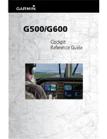
Page 1: ...G500 G600 Cockpit Reference Guide...

Page 2: ...s of Garmin Ltd or its subsidiaries These trademarks may not be used without the express permission of Garmin NavData is a registered trademark of Jeppesen Inc ChartView is a trademark of Jeppesen Inc...

Page 3: ...ERCHANTABILITY OR FITNESS FOR A PARTICULAR PURPOSE STATUTORY OR OTHERWISE THIS WARRANTY GIVES YOU SPECIFIC LEGAL RIGHTS WHICH MAY VARY FROM STATE TO STATE IN NO EVENT SHALL GARMIN BE LIABLE FORANY INC...

Page 4: ...m clearance altitudes WARNING The Garmin G500 G600 systems have a very high degree of functional integrity However the pilot must recognize that providing monitoring and or self test capability for al...

Page 5: ...f the weather information shown by the data link weather product Due to time delays inherent in gathering and processing weather data for data link transmission the weather information shown by the da...

Page 6: ...d 165 East WARNING Do not use Terrain SVT information for primary terrain avoidance Terrain SVT is intended only to enhance situational awareness CAUTION The United States government operates the Glob...

Page 7: ...g in long and near term planning decision making The system lacks sufficient resolution and updating capability necessary for aerial maneuvering associated with immediate decisions NOTE Do not rely so...

Page 8: ...5 NOTE Terrain data is not displayed when the aircraft latitude is greater than 75 North or 60 South NOTE Terrain SVT is standard when the Synthetic Vision Technology SVT option is installed TheTAWS o...

Page 9: ...d G600 CRGs F 10 23 12 Update reflects software v6 11 upgrade E 08 23 11 Update reflects software v6 00 upgrade D 11 30 10 Upgrade reflects software v4 00 and v5 00 upgrade C 10 26 09 Added subscripti...

Page 10: ...ed Vertical Speed V S Tape and Window Image 32 Added SXM Weather GFDS Weather FIS B Weather and Stormscope groups to Map Setup Options table 33 Added VRP Viewing Range selection to aviation group in t...

Page 11: ...4 HSI Bearing Pointers 14 Marker Beacon Annunciations 16 Miscompare Annunciations 17 Autopilot AP 19 GAD 43 Attitude 19 Heading 20 Altitude Capture Optional Upgrade 20 Autopilot Navigation 20 GPSS 21...

Page 12: ...Page Optional 63 Position Reporting Page 65 Iridium Phone Page Optional 66 System Status Page 68 Flight Plan Group 69 Active Flight Plan Page 69 Viewing Your Active Flight Plan 69 Waypoint Informatio...

Page 13: ...units or Line Replaceable Units LRUs LRUs have a modular design and can be installed directly behind the instrument panel or in a separate avionics bay if desired This design greatly eases troublesho...

Page 14: ...Markings dependent upon installation configuration 2 Wind Vector Displays direction and speed of wind 3 Heading Select Key Press HDG and turn PFD knob to set heading bug 4 Course Select Key Press CRS...

Page 15: ...are available have the labels shown as white text on a black background Soft keys that are selected have the labels shown as black text on a gray background Soft keys that are unavailable have the la...

Page 16: ...If the current acceleration will cause the airspeed to exceed Vne in six seconds the airspeed is displayed in yellow If the current airspeed exceeds Vne the pointer changes to red with white text NOTE...

Page 17: ...Setup page on the first page of the Aux page group When active on the V speeds are displayed at their respective locations to the right of the airspeed scale Glide Reference Marker Vr Reference Marker...

Page 18: ...the altitude will be in six seconds if the current vertical speed is maintained Altitude Bug Setting Altitude Trend BARO Setting Current Altitude Altitude Tape Altitude Bug Altitude Minimums Bug Barom...

Page 19: ...ll be displayed at the bottom of the altitude tape if the selected altitude minimums bug is off of the tape When the aircraft is within 100 feet of the selected altitude minimums setting the bug and t...

Page 20: ...ob to the ALTITUDE portion of the MINIMUMS section 4 Turn the small MFD knob to enter the desired altitude Press the ENT key to confirm selection 5 When finished press the small MFD knob to exit the M...

Page 21: ...e Bug Altitude Bug Setting The Altitude Bug provides visual and aural altitude alerting Aural alerting occurs within 200 feet or 1000 feet as configured of the Altitude Bug setting or when deviating b...

Page 22: ...ons on selecting wind vector style Wind Vectors can only be calculated when the aircraft is in the air Wind Vector Field Wind Vector Display Vertical Speed V S The Vertical Speed Tape and Vertical Spe...

Page 23: ...puts The units C or F and temperature reference are selected on the AUX SYSTEM SETUP page The temperature reference can be selected to one of the following choices Static Air Temperature SAT This is t...

Page 24: ...mer Start StopTimer Reset Timer Clock and Timer Functions Attitude Indicator The standby mechanical Attitude Indicator in your aircraft is either a Ground Pointer or a Roll Pointer configuration The G...

Page 25: ...The indicator moves with the roll pointer and moves laterally away from the pointer to indicate lateral acceleration Slip skid is indicated by the location of the bar relative to the pointer One bar...

Page 26: ...rse HSI Bearing Pointers NOTE The Bearing Pointer for navigation source 1 BRG1 will be an arrow with a single line The Bearing Pointer for navigation source 2 BRG2 will be an arrow with a double line...

Page 27: ...cted source for BRG 1 bearing pointer BRG2 Pointer BRG1 Pointer Selected source for BRG 2 bearing pointer Bearing Pointers on the HSI CDI Source GPS Mode GPS Advisory Suspend MSG LOI OBS SUSP GPS1 GPS...

Page 28: ...s the current CDI scaling of the GPS navigator Refer to the GPS navigator pilot s guide for a description of each mode GPS Advisory MSG Displays when a new advisory message is displayed on the GPS nav...

Page 29: ...HT DISPLAY PFD PRIMARY FLIGHT DISPLAY Miscompare Annunciations For complete description and conditions of miscompare annunciations refer to the G500 G600 Pilot s Guide P N 190 00601 02 Pitch and Roll...

Page 30: ...y two sources of navigation GPS or NAV VOR or LOC Press the CDI soft key to toggle between the available CDI modes GPS or VOR If a second GPS source or NAV source is available pressing the 1 2 soft ke...

Page 31: ...r 1 Allow all avionics to complete power up and begin normal operation 2 Engage the autopilot while on the ground 3 Press and release the AP TEST soft key and verify that the autopilot disconnects nor...

Page 32: ...terface Some autopilot installations support arming and disarming of the selected altitude using the ALT key on the PFD The PFD knob window will indicate when this function is available The selected a...

Page 33: ...ssing and holding the HDG key on the PFD If the installation uses the HDG key on the PFD the PFD knob window will display the GPSS HDG mode options NOTE The GDU 620 has the ability to emulate GPSS rol...

Page 34: ...to control vertical speed with certain autopilots Refer to the Airplane Flight Manual and autopilot system documentation for instructions on how to use the vertical speed mode if available Adjust the...

Page 35: ...top of the PFD Refer to the Airplane Flight Manual and autopilot system documentation for details on the autopilot mode annunciations When autopilot annunciations are displayed at the top of the PFD t...

Page 36: ...information is shown on the PFD SVT offers a three dimensional view of terrain and obstacles Terrain and obstacles that pose a threat to the aircraft in flight are shaded yellow or red Obstacle Zero P...

Page 37: ...he PFD soft key followed by the SYN VIS soft key then the SYN TERR soft key NOTE SVT features are not a substitute for standard course and altitude deviation information using the CDI VSI and VDI Disp...

Page 38: ...e MFD knob Use to move between page groups 3 Small MFD knob Use to move within page groups 4 Enter Validates or confirms a menu selection or data entry 5 Clear Erases information cancels entries or re...

Page 39: ...and Page are shown at the bottom of the MFD Changing Settings within a Page 1 Press the MENU key and make the necessary adjustments with the large MFD knob and small MFD knobs 2 Press the small MFD kn...

Page 40: ...Video Video 1 Video 2 Setup Charts NOTAM Detail Select Header Plan Profile Minimums AUX continued AUX ALERTS TRND ACK CAPTURE BACK Iridium Phone Dial Hang Up Vol Keys 1234 5678 90 Answer Weather Map 1...

Page 41: ...he large MFD knob to move the map pointer left and right horizontally 3 Turn the small MFD knob to move the map pointer up and down vertically 4 Press the small MFD knob again to exit panning mode Sel...

Page 42: ...ewing Navigation Map 1 or Navigation Map 2 of the Map Page Group press the MAP soft key Select the Traffic TOPO or Terrain overlays by pressing the appropriate soft key Measuring Distances 1 While vie...

Page 43: ...ap Weather Traffic or Aviation Available Groups 4 Press the ENT key to select the group and set your preferences 5 Turn the large MFD knob to move between fields 6 Turn the small MFD knob to display a...

Page 44: ...ewing Range Off to 15 NM Lat Lon Viewing Range Off to 500 NM Selected Alt Range Arc On or Off SXM WEATHER NEXRAD Data Viewing Range Off to 500 NM NEXRAD Cell Movement On or Off NEXRAD Legend On or Off...

Page 45: ...ail when zooming in on airports at close range The airport display on the map reveals taxiways with identifying letters numbers and airport landmarks including ramps buildings control towers and other...

Page 46: ...on that displays video provided by an externally mounted video source on the aircraft 1 While viewing the Map function turn the small MFD knob to the third page of the map group Display of External Vi...

Page 47: ...Display When a traffic alert is generated by an interfaced traffic system the PFD will display a traffic annunciator and the MFD will have a pop up screen displaying the detected traffic if not viewi...

Page 48: ...nd Climbing Traffic Advisory 200 ft Above and Descending Ownship Symbol Non Bearing Traffic System is Unable to Determine Bearing Aircraft Distance is 2 0 NM 1100 ft Above and Descending Traffic Map T...

Page 49: ...Key Description BELOW Displays traffic from 9900 to 2700 ft NORMAL Displays traffic from 2700 to 2700 ft ABOVE Displays traffic from 2700 to 9900 ft UNRSTD All traffic is displayed unrestricted from 9...

Page 50: ...0 displays up to eight traffic targets within a 7 5 NM radius from 3000 feet below to 3500 feet above the requesting aircraft Displaying TIS Traffic While viewing the Traffic Page of the Map Page Grou...

Page 51: ...tails suchastype direction groundspeed and motion Selected Traffic Info ADS B and TCAS Status and Altitude Filter Selected Vector Motion and Duration Turn Cursor Knob for Next Target Map Orientation R...

Page 52: ...ion Vector When Absolute Motion Vectors are selected the vectors extending from the traffic targets depict the target reported track and speed over the ground When Relative Motion Vectors are selected...

Page 53: ...TE TAWS alerts will be generated by the GPS TAWS unit on the PFD if an external TAWS unit is installed and interfaced to the G500 G600 TERRAIN PROXIMITY is a non TSO C151b certified terrain awareness...

Page 54: ...TAWS system as defined in TSO C151b Viewing Terrain NOTE Obstacles Wires will be removed from the Terrain TAWS page when range RNG exceeds 10 NM While viewing the Terrain TAWS B page of the Map Page...

Page 55: ...up alert appears on the MFD To acknowledge the pop up alert and return to the currently viewed page press the CLR key To acknowledge the pop up alert and go to the TERRAIN SVT page press the ENT key T...

Page 56: ...ustomizing the Weather Map 1 While viewing any of the XM Weather Map pages in the WX Page Group press the MENU key to display the page menu Press ENT 2 Turn the small MFD knob to select Weather Setup...

Page 57: ...ange Off 10 NM to 500 NM METAR Data Viewing Range Off 10 NM to 500 NM Surface Data Viewing Range Off 10 NM to 500 NM Frz Lvl Data Viewing Range Off 10 NM to 500 NM Wnds Aloft Data Viewing Range Off 10...

Page 58: ...ther the LEGEND soft key ENT key or the small MFD knob Changing Forecast Time 1 When the Surface Data products Surface Analysis and City Forecasts are displayed the time period for these forecasts can...

Page 59: ...ting GFDS information an access code and system ID will need to be assigned For more information on GFDS and how to register refer to the latest revision of the G500 G600 Pilot s Guide P N 190 00601 0...

Page 60: ...Request Page Configuring GFDS Data Request Page 1 Turn the large MFD knob to the Coverage box Press ENT to select or deselect the coverage areas Selected coverage areas are denoted by a green check m...

Page 61: ...each page Customizing the Weather Map 1 While viewing any of the FIS B Weather Map pages in the FIS B Page Group press the MENU key to display the page menu 2 Turn the small MFD knob to select Weather...

Page 62: ...t Map Orientation North Up Track Up NEXRAD Data Viewing Range Off 10 NM to 500 NM NEXRAD Legend On Off Source CONUS Regional Combined SIG AIR Viewing Range Off 10 NM to 500 NM PIREPS Data Viewing Rang...

Page 63: ...601 03 Rev H WX GROUP WX GROUP WEATHER RADAR Weather Radar Optional Weather Radar Map Page Soft Keys Found on Weather Radar Map Page Weather Alert GWX only Control Window Operating Mode Operating Mode...

Page 64: ...ge to the radar assembly Displaying Weather on the Weather Radar Page 1 Turn the large MFD knob to select the last page of the WX Page Group 2 Press the MODE soft key 3 If the aircraft is on the groun...

Page 65: ...2 Turn the small MFD knob to select FULL 60 40 or 20 scan 3 If desired readjust the Bearing Line to change the center of the Sector Scan Turn the large MFD knob to move cursor to the BEARING field an...

Page 66: ...he weather radar system is in the Weather or Ground Map Mode upon landing the system automatically switches to Standby Mode Altitude Compensated Tilt ACT GWX 70 only Altitude Compensated Tilt ACT auto...

Page 67: ...flash Turn the small MFD knob to change the brightness of the video output 3 Turn the large MFD knob to CONTRAST and turn the small MFD knob to change the contrast level of the video output 4 Turn th...

Page 68: ...he AUTO the LEVEL will adjust in response to ambient light or a lighting bus as configured during installation Setting Airspeed References 1 While viewing the System Setup Page of the Aux Page Group p...

Page 69: ...Style 1 Displays headwind and crosswind components Style 2 Displays total wind direction and speed Style 3 Displays total wind direction with headwind and crosswind speed components Style 4 Displays...

Page 70: ...if a second GDU 620 is installed DATABASES depend on the installation configuration CHART STREAMING only appears if DATABASES is turned on 1 While viewing the System Setup Page of the Aux Page Group...

Page 71: ...sired format and press ENT to confirm your selection Setting Time Offset 1 While viewing the System Setup Page of the Aux Page Group press the small MFD knob Turn the large MFD knob to the time offset...

Page 72: ...ode Setting Altitude and Vertical Speed Units 1 While viewing the System Setup Page of the Aux Page Group press the small MFD knob and turn the large MFD knob to move to the desired field of the MFD D...

Page 73: ...ure Press ENT to confirm your selection and press the small MFD knob to exit editing mode Data Link 1 Press the small MFD knob and turn the large MFD knob to move to the Data Link box 2 Turn the small...

Page 74: ...ptional Soft Key Found on XM Information Page While viewing the Aux Group turn the small MFD knob to display the XM Information screen This page contains the Data Radio and Audio Radio IDs The only op...

Page 75: ...o increment up or down one channel at a time in the active category 5 Press CHNL and then the DIR CH soft key to directly select a channel in the active channel field Turn the small MFD knob and large...

Page 76: ...MUTE soft key To restore the radio volume press MUTE again or the VOL or VOL soft keys Storing a Preset Channel While viewing the XM Radio page you may set a preset for the Active Channel Press the PR...

Page 77: ...ng Page Position Reporting Page Position Reporting Status The Status window shows the time until the next data transmission and the status of the reporting system Settings Window 1 While viewing the P...

Page 78: ...Field Iridium Phone Page For detailed use of the Iridium Phone system refer to the latest revision of the G500 G600 Pilot s Guide P N 190 00601 02 Call Suppression 1 While viewing the Iridium Phone pa...

Page 79: ...urn the small MFD knob to display the contents of the Phone Book Catalog and highlight the desired entry Press ENT to select the catalog entry 3 Turn the large MFD knob to highlight the DELETE key Pre...

Page 80: ...unit is present and operating properly while a red X indicates an absence or failure System Status 1 While viewing the System Status page of the Aux Page Group press the DB ACTV soft key and turn the...

Page 81: ...irst page of the Flight Plan page group No changes to the flight plan can be made from the GDU 620 All flight plan changes must be made from the GPS unit Active Flight Plan Page 1 While viewing the Ac...

Page 82: ...le viewing the Waypoint Information page of the FPL Page Group press the small MFD knob and then turn the small MFD knobs to enter or select the waypoint You can also turn the small MFD knob countercl...

Page 83: ...s are displayed in full color with high resolution The MFD depiction shows the aircraft position on the moving map in the plan view of approach charts and on airport diagrams ChartView requires an ena...

Page 84: ...show FPL NRST or RECENT 4 Turn the large MFD knob to highlight the desired airport then press ENT Display Charts From Flight Plan Display Charts Of Nearest Airport Display Charts From Recent Choices...

Page 85: ...he ENT key 3 Turn the small MFD knob to select the altitude Press ENT to set the altitude Changing Day Night View 1 While viewing the Charts page of the FPL Page Group press the MENU key to display th...

Page 86: ...03 Rev H FPL GROUP FPL GROUP CHARTS PAGEViewing NOTAMs ChartView Only In the event there is an active NOTAM Notice to Airmen for a particular chart the NOTAM soft key will be available To view the in...

Page 87: ...ersionary mode AHRS 1 or AHRS 2 is using the backup GPS information AHRS 1 or AHRS 2 is not receiving backup GPS information Two GPS devices are configured as present and AHRS 1 is not receiving GPS d...

Page 88: ...receiver ADS B fault 1090 receiver FIS B weather has failed GDL 88 ADS B Failure Unable to transmit ADS B messages GDL 88 ADS B fault GDL 88 needs service GDL 88 ADS B is not transmitting position Ch...

Page 89: ...mmunication with sensors is halted or lost ETM CAPTURE Engine Trend Monitor data capture ADAS engine monitoring system is recording trend data ETM EXCEED Engine Trend Monitor exceedance advisory ADAS...

Page 90: ...9 Heading Timeout fault AHRS A429 Heading Invalid fault Power Supply fault AC reference is lost Application SCI integrity fault Configuration integrity fault Calibration integrity fault Unit fault GAD...

Page 91: ...RU LRU COOLING The indicated LRU has insufficient cooling Display is automatically dimmed to reduce power usage LRU DB ERR Error exists with the indicated LRU database LRU KEYSTK The indicated LRU key...

Page 92: ...rrain or obstacle database error in TAWS B or TERRAIN SVT only TRAFFIC ADS B In traffic alerting has failed ADS B In traffic has failed TAS TCAS has been in standby for more than 60 seconds TAS TCAS i...

Page 93: ...Up or Wire Wire Pull Up Pull Up FLTA Terrain Caution RTC C ITI C Terrain Ahead Terrain Ahead or Caution Terrain Caution Terrain FLTA Obstacle Caution ROC C IOI C Obstacle Ahead Obstacle Ahead or Caut...

Page 94: ...None No GPS position Excessively degraded GPS signal Terrain System Not Available Terrain SVT System Test Fail Terrain System Failure Alert Type PFD MFD Alert Annunciation Aural Message FLTA Terrain C...

Page 95: ...iced Airport Towered Non serviced Airport Non towered Serviced Airport Towered Serviced Airport Soft Surface Serviced Airport Soft Surface Non serviced Airport Private Airport Heliport Intersection LO...

Page 96: ...on Under Construction Zones Designated Water Areas Traffic Symbols TAS Symbol Description Other Traffic Proximity Advisory PA Traffic Advisory TA Traffic Advisory Off Scale TAS TCAS Traffic Symbols TI...

Page 97: ...e in Air Brown on Ground Basic Off scale Selected Traffic Proximate Non Directional Traffic Proximate Directional Traffic Proximate Off scale Selected Traffic Non Directional Alerted Traffic Off Scale...

Page 98: ...ude Black Terrain is more than 1 000 ft below the current aircraft altitude Terrain Altitude Color Descriptions Threat Location Unlighted Obstacle Projected Flight Path 1000 ft 100 ft Threshold Terrai...

Page 99: ...ht is greater than 1 000 ft AGL Lighted Obstacle height is greater than 1 000 ft AGL Tower Windmill Windmill in Group Power Line Obstacle Icon Types Symbol Description Red Obstacle is at or within 100...

Page 100: ...y Enabled and Not Available Indicator Point Obstacle Enabled and Available Indicator Point Obstacle Enabled and Not Available Indicator Wire Obstacles Enabled and Available Indicator Wire Obstacles En...

Page 101: ...and gray when expired Expired products will not be shown on the display Weather Product Expiration Time Minutes NEXRAD NEXRAD and Echo Top are Mutually Exclusive 30 Echo Top Cloud Top and Echo Top Mut...

Page 102: ...mple Airplane 2 Blade Rotorcraft 3 Blade Rotorcraft 4 Blade Rotorcraft Arrow Default Map Cursor Measuring Cursor MFD Wind Vector w valid GPS solution Parallel Track Waypoint Restricted Prohibited Warn...

Page 103: ......

Page 104: ...503 364 2138 Garmin Europe Ltd Liberty House Bulls Copse Road Hounsdown Business Park Southampton SO40 9RB U K Tel 44 0 870 850 1243 Fax 44 0 238 052 4004 Garmin Corporation No 68 Jangshu 2nd Road Xiz...

Reviews: