background image

G500(H)/G600/G700 TXi

Pilot's Guide

Summary of Contents for G500

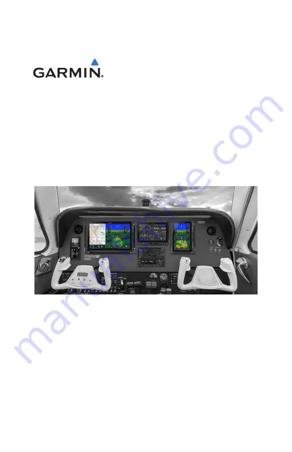
Page 1: ...G500 H G600 G700 TXi Pilot s Guide ...

Page 2: ...y Garmin is under license Other trademarks and trade names are those of their respective owners 2019 SD is a registered trademark of SD 3C LLC All rights reserved Iridium is a registered trademark of Iridium Communications Inc All rights reserved The term Wi Fi is a registered trademark of the Wi Fi Alliance For information regarding the Aviation Limited Warranty refer to Garmin s website For avia...

Page 3: ... 21 1 11 Manual Updates 1 21 1 11 1 Database Update Page 1 21 1 12 Automatic Updates 1 23 1 13 Database Concierge 1 24 1 14 Database SYNC 1 26 1 15 Chart Streaming 1 27 Connectivity 1 28 1 16 Flight Stream 510 Setup 1 28 1 17 Bluetooth Setup 1 29 1 17 1 Managing Paired Devices 1 29 1 18 Wi Fi Setup 1 30 1 18 1 Connecting to Wi Fi 1 30 1 18 2 Viewing Wi Fi Information 1 31 Pilot Settings 1 32 1 19 ...

Page 4: ...ciations 1 56 1 28 2 EIS Failure Annunciations 1 57 Logs 1 58 1 29 Flight Data Logging 1 58 1 29 1 Exporting to SD Card 1 60 1 29 2 Streaming to Garmin Pilot 1 62 1 30 Exceedance Logging 1 63 1 30 1 Exceedance Alerts 1 65 1 30 2 Exceedance Details 1 66 1 30 3 Exporting to SD Card 1 66 Compatible Equipment 1 67 1 31 Line Replaceable Units 1 67 1 31 1 LRU Status 1 68 1 31 2 Integrated Standby Instru...

Page 5: ...Annunciations 2 34 2 10 CDI 2 37 2 10 1 Course Pointer Types 2 38 2 10 2 Cross Track Error Indication 2 38 2 10 3 CDI Source Selection 2 39 2 10 4 Selected Course with VOR LOC 2 40 2 10 5 Selected Course with GPS 2 40 2 10 6 Automatic Source Selection 2 41 2 10 7 Auto Slewing 2 42 2 11 LDI 2 43 2 11 1 Reverse Sensing Correction 2 43 2 12 VDI 2 44 2 12 1 VNAV Deviation Indications 2 45 2 13 CDI VDI...

Page 6: ...ode 3 25 3 9 Servo Heading Reference 3 25 3 10 Mode Annunciations 3 26 3 10 1 AP Basic Mode Annunciations 3 26 3 10 2 AP Lateral Vertical Mode Annunciations 3 27 3 10 3 Autopilot Alerts 3 28 3 11 Autopilot Preflight Test 3 30 4 MULTI FUNCTION DISPLAY 4 1 MFD Setup 4 3 4 1 Nearest Airport Criteria 4 4 4 2 MFD Resize Option 4 4 Map 4 5 4 3 Map Interactions 4 8 4 4 Map Overlays 4 11 4 4 1 Overlay Con...

Page 7: ...eather Display 5 2 5 1 Weather Products 5 3 Datalink Weather 5 5 5 2 Weather Page Interactions 5 6 5 3 Weather Product Age 5 8 5 4 Precipitation 5 9 5 4 1 NEXRAD 5 9 5 4 2 Connext 5 11 5 5 Echo Tops 5 12 5 6 Clouds 5 12 5 6 1 Cloud Tops 5 12 5 6 2 IR Satellite 5 13 5 7 Lightning 5 13 5 8 METARs and TAFs 5 14 5 9 Cell Movement 5 15 5 10 AIRMETs 5 16 5 10 1 Textual AIRMETs 5 16 5 10 2 Graphical AIRM...

Page 8: ...e Modes Symbols 5 40 5 27 2 Views 5 41 Airborne Weather Radar 5 42 5 28 Weather Radar Page 5 42 5 29 Weather Radar Setup 5 44 5 29 1 Sector Scan 5 44 5 29 2 Stabilization 5 45 5 29 3 WATCH 5 45 5 29 4 Weather Alert 5 46 5 29 5 Altitude Compensated Tilt 5 46 5 29 6 Turbulence Detection 5 47 5 29 7 Ground Clutter Suppression 5 47 5 30 Radar Modes 5 48 5 30 1 Mode Key 5 48 5 31 Radar Controls 5 52 5 ...

Page 9: ...rain 7 2 7 1 1 GSL Altitude Indicated Altitude 7 3 7 2 Database Limitations 7 4 Terrain Display 7 5 7 3 Terrain Page 7 5 7 4 Terrain Setup 7 7 7 5 Terrain Proximity 7 8 7 5 1 Terrain Elevation Depictions 7 9 7 5 2 Obstacle Elevation Depictions 7 11 Terrain Alerting 7 13 7 6 Alert Types 7 13 7 6 1 Alerting Thresholds 7 15 7 6 2 Inhibiting TAWS and Terrain FLTA Alerts 7 18 7 7 Terrain FLTA 7 19 7 7 ...

Page 10: ...1 8 12 3 En Route 8 42 8 12 4 Post Flight 8 42 8 13 Engine Advisories 8 42 Electrical 8 43 8 14 Electrical Gauges 8 43 Fuel 8 44 8 15 Fuel Computer 8 44 8 15 1 Preset Fuel Quantities 8 45 8 15 2 Fuel Flow Calibration 8 46 Engine Alerts 8 47 9 ABNORMAL OPERATIONS 9 1 Backup Instruments 9 2 9 1 Display Backup 9 2 9 1 1 Standby PFD Display Options 9 3 9 1 2 Composite Display Backup Mode 9 4 9 2 Backu...

Page 11: ...17 10 Rev H Pilot s Guide ix Table of Contents 9 5 1 EDM Activation 9 25 9 5 2 EDM Inhibit 9 27 9 5 3 EDM Override 9 29 9 5 4 EDM Active Discrete Output 9 30 10 QUALIFICATION 10 1 10 1 Glove Qualification 10 1 ...

Page 12: ...x Pilot s Guide 190 01717 10 Rev H INTENTIONALLY LEFT BLANK ...

Page 13: ... SOLE MEANS OF NAVIGATION BASEMAP DATA IS INTENDED ONLY TO SUPPLEMENT OTHER APPROVEDNAVIGATIONDATASOURCESANDSHOULDBECONSIDEREDONLYANAID TO ENHANCE SITUATIONAL AWARENESS WARNING DO NOT RELY SOLELY UPON THE DISPLAY OF TRAFFIC INFORMATION TO ACCURATELY DEPICT ALL OF THE TRAFFIC WITHIN RANGE OF THE AIRCRAFT DUE TO LACK OF EQUIPMENT POOR SIGNAL RECEPTION AND OR INACCURATE INFORMATION FROM AIRCRAFT OR G...

Page 14: ...WARNING DO NOT RELY ON THE ACCURACY OF ATTITUDE AND HEADING INDICATIONS IN GEOGRAPHIC AREAS WHERE VARIATION IN THE EARTH S MAGNETIC FIELD EXISTS THIS INCLUDES NORTH OF 72 NORTH LATITUDE AT ALL LONGITUDES SOUTH OF 70 SOUTH LATITUDE AT ALL LONGITUDES NORTH OF 65 NORTH LATITUDE BETWEEN LONGITUDE 75 W AND 120 W NORTHERN CANADA NORTH OF 70 NORTH LATITUDE BETWEEN LONGITUDE 70 W AND 128 W NORTHERN CANADA...

Page 15: ...RIMARYTERRAINOROBSTACLEAVOIDANCE TAWS IS INTENDED ONLY TO ENHANCE SITUATIONAL AWARENESS CAUTION DO NOT CLEAN DISPLAY SURFACES WITH ABRASIVE CLOTHS OR CLEANERS CONTAINING AMMONIA THEY WILL HARM THE ANTI REFLECTIVE COATING CAUTION ENSURE THAT ANY UNIT REPAIRS ARE MADE BY AN AUTHORIZED GARMIN SERVICE CENTER UNAUTHORIZED REPAIRS OR MODIFICATIONS COULD VOID BOTH THE WARRANTY AND AFFECT THE AIRWORTHINES...

Page 16: ...the aircraft more than 100 yards away from the source of the interference should alleviate the condition NOTE Use of polarized eye wear may cause the flight displays to appear dim or blank NOTE This product its packaging and its components contain chemicals known to the State of California to cause cancer birth defects or reproductive harm This notice is being provided in accordance with Californi...

Page 17: ... presented by the system It is the pilot s responsibility to operate in accordance with established AFM S and regulatory guidance or limitations as applicable to the pilot the aircraft and installed equipment NOTE The pilot operator must review and be familiar with Garmin s database exclusion list as discussed in SAIB CE 14 04 to determine what data may be incomplete The database exclusion list ca...

Page 18: ...E When using Stormscope there are several atmospheric phenomena in addition to nearby thunderstorms that can cause isolated discharge points in the strike display mode However clusters of two or more discharge points in the strike display mode do indicate thunderstorm activity if these points reappear after the screen has been cleared NOTE The navigation databases used in Garmin navigation systems...

Page 19: ...ON DATE CHANGE DESCRIPTION A 05 19 17 Initial Release B 01 16 18 Production Release C 01 18 18 Minor edits D 01 24 18 Minor edits E 08 17 18 Updates for software v2 20 F 10 16 18 Updates for software v2 30 G 03 14 19 Updates for software v3 00 H 05 21 19 Updates for software v3 01 ...

Page 20: ...D Controller section 2 Modified CDI Source key label Added standard rate turn indicator information Added information about selected altitude behavior during emergency descent mode 3 Added AP Engaged Indication topic to Flight Director section Added low bank mode information 4 Added MFD Resize Option section 8 Added information about the following turbine EIS features Customizable EIS gauge labels...

Page 21: ... manuals SECTION TITLE 1 System Description 2 Primary Flight Display 3 Advanced Features 4 Multi function Display 5 Weather Awareness 6 Traffic Awareness 7 Terrain Awareness 8 Fuel Engine Indicating System 9 Abnormal Operations 10 Qualification The layout and design of this guide is to provide clear concise sections written in the logical order of a pilot s flight instrument and systems scan ...

Page 22: ...Surveillance Broadcast AFM Aircraft Flight Manual AFMS Aircraft Flight Manual Supplement AGL Above Ground Level AHRS Attitude Heading Reference System AIM Airman s Information Manual AIRB Basic Airborne Application ALT Altitude Hold AP Autopilot ATC Air Traffic Control ATCRBS Air Traffic Control Radar Beacon System ATK Along Track C CAT Carburetor Air Temperature CDI Course Deviation Indicator CDU...

Page 23: ...ation System ENR En Route ESP Electronic Stability and Protection F FAF Final Approach Fix FDC Flight Data Center FIS B Flight Information Services Broadcast FIT Flight Into Terrain FLTA Forward Looking Terrain Avoidance FMS Flight Management System FPM Feet Per Minute FS Flight Stream G GCS Ground Clutter Suppression GDC Garmin Air Data Computer GDL Garmin Data Link GDU Garmin Display Unit GEA Ga...

Page 24: ...ar H HDG Heading HOT Hazardous Obstacle Transmission HSI Horizontal Situation Indicator HTAWS Helicopter Terrain Awareness and Warning System I IAF Initial Approach Fix IAS Indicated Airspeed IAT Induction Air Temperature IFR Instrument Flight Rules IGRF International Geomagnetic Reference Field ILI Imminent Line Impact ILS Instrument Landing System ITT Interstage Turbine Temperature IOI Imminent ...

Page 25: ...R Meteorological Terminal Aviation Routine Weather Report MFD Multi Function Display MGT Measured Gas Temperature MOA Military Operations Area MSL Mean Sea Level N NAVAID Navigation Aid NCR Negative Climb Rate NDB Non Directional Beacon NEXRAD Next Generation Radar NRST Nearest O OAT Outside Air Temperature OBS Omni Bearing Selector OCN Oceanic P PCL Pilot Controlled Lighting PDA Premature Descent...

Page 26: ...ace Situation Awareness SVT Synthetic Vision Technology SXM SiriusXM Weather T TA Traffic Advisory TAF Terminal Aerodrome Forecast TAS Traffic Advisory System TAT Total Air Temperature TAWS Terrain Awareness and Warning System TCAD Traffic Alert and Collision Avoidance Devices TCAS Traffic Alert and Collision Avoidance System TERM Terminal TFR Temporary Flight Restriction TIS Traffic Information S...

Page 27: ...Indicator VFR Visual Flight Rules VLOC VOR Localizer VNAV Vertical Navigation VOR Very High Frequency Omni directional Range VRP Visual Reporting Point VS Vertical Speed VSI Vertical Speed Indicator W WAAS Wide Area Augmentation System WATCH Weather Attenuated Color Highlight WP Waypoint ...

Page 28: ...riusXM Satellite Radio Activation Instructions 190 00355 04 WEBSITE ADDRESS Aviation Limited Warranty https www garmin com en US legal aviation limited warranty Database Concierge Go to http www flygarmin com support and select Database Management ADS B Academy https www garmin com us intheair ads b Connext http www garmin com connext ...

Page 29: ...pdates 1 23 1 13 Database Concierge 1 24 1 14 Database SYNC 1 26 1 15 Chart Streaming 1 27 CONNECTIVITY 1 16 Flight Stream 510 Setup 1 28 1 17 Bluetooth Setup 1 29 1 18 Wi Fi Setup 1 30 PILOT SETTINGS 1 19 Display Brightness Control 1 32 1 20 System Status Page 1 33 1 21 Click Volume 1 33 1 22 Clock 1 33 1 23 Weather Display Shortcut 1 33 1 24 Unit Selections 1 34 CREW PROFILES 1 25 Crew Profile S...

Page 30: ...isplay The MFD can be selectively hidden or shown When hidden the PFD expands into the MFD space If installed the EIS function always shows and occupies either the left or right edge of the display GDU 700P PFD MFD EIS MFD EIS The GDU 700P provides a single PFD MFD EIS or in single engine piston EIS a combined MFD EIS function In some installations it provides backup PFD or EIS information in the ...

Page 31: ...0 01717 10 Rev H Pilot s Guide 1 3 System Description 1 1 Display Layout Power Key Photocell Top SD Card Slot Bottom SD Card Slot Right Inner Outer Knobs Left Inner Outer Knobs Bezel Garmin Display Units ...

Page 32: ...ls for unit operation Power Key Powers the unit on or off Allows manual transition into display backup mode Photocell Measures cockpit ambient light level to automatically adjust display brightness for day and night SD Card Slots Each unit has two SD card slots Each slot s purpose depends on display type Inner Outer Knobs Units have a dual concentric knob near the bottom of bezel GDU 1060 has two ...

Page 33: ...190 01717 10 Rev H Pilot s Guide 1 5 System Description GDU 700P DISPLAY CONFIGURATIONS 1 Single engine piston EIS only EIS Only PFD Only MFD Only EIS MFD 1 ...

Page 34: ...1 6 Pilot s Guide 190 01717 10 Rev H System Description GDU 700L DISPLAY CONFIGURATIONS Piston EIS Only PFD Only Single Engine Piston EIS MFD ...

Page 35: ...on Indicators Datalink Weather Display 1 Radar Altimeter 1 Autopilot Annunciations 1 Flight Director 1 Synthetic Vision 1 Flight Path Marker 1 System Advisories Safety Monitors 1 GPS NAV Status Display Backup 1 4 Terrain Avoidance 1 Navigation Map Traffic 1 Terrain Charts Flight Plan Weather 1 Waypoint Information Music Services 1 Terrain Avoidance 1 Engine Data 1 System Advisories Video 1 Fuel Qt...

Page 36: ...momentarily illuminates On MFD The start up screen presents the unit software version the name and status of all installed databases and controls for selecting a crew profile 1 4 1 Power Off Options WARNING NEVER ATTEMPT TO POWER OFF THE UNIT WHILE AIRBORNE UNLESS OPERATIONAL PROCEDURES DICTATE Pushing the Power key once opens a pop up menu Selectable display options allow you to Power off unit Cl...

Page 37: ...ight card slot to perform a software update INSERT AN SD CARD When inserting an SD card 1 Verify unit power if off and the slot is empty 2 Hold card in the proper orientation GDU 1060 700P label faces left edge of display screen GDU 700L label faces top edge of display screen 3 Ensure back edge of card is flush with display bezel after insertion EJECT AN SD CARD 1 Power off the unit 2 Release the ...

Page 38: ...motion that involves touching an object then sliding your finger across the screen and lifting up Use this gesture for Viewing and scrolling lists Panning across a map or chart display Zooming HSI map or rotorcraft PFD VFR map display upward and downward swipes only FLICK Swiping the screen in a quick upward or downward motion Information moves at a fast speed faster than by holding the arrow key ...

Page 39: ...ates unread system advisories Inputs specified value Displays context menus Scrolls up Returns to previous page Scrolls down Cancels current function without inputting data Indicates corresponding item is selected e g database update Allows resizing of the MFD and PFD screens 1 2 Toggle keys turn a specific function on or off The current state of the function is indicated below the key label On Of...

Page 40: ...ontrols into an expandable pane allowing access to multiple functions on a single page Fly out menus slide out from the right side of the display when an object or menu item is selected on the underlying page Menu Controls Underlying Page Hidden Slide over windows slide up from the bottom of display Underlying Page Hidden ...

Page 41: ...ault or previously selected value Tabs group information into individual panes Content includes scrolling lists data fields function keys or a combination of controls Tabs are located along the left side or bottom edge of a pane Inactive Tabs Lists containing a combination of controls typically appear within a tab and open to the first list item Toggle keys either enable or disable list items In s...

Page 42: ...e 190 01717 10 Rev H System Description 1 6 5 Keypads The GDU employs multiple keypad types to serve specific settings and functions Tapping Layout changes the format between ABCDE and QWERTY Numeric Alphanumeric QWERTY ...

Page 43: ...tial field page selections Moving cursor forward or backward within data field Inner Knob Turn Inputting data Modifying individual characters in data entry field Zooming Controlling weather radar range Inner Knob Push Entering a specified numerical value EIS KNOB FUNCTIONS Outer Knob Cursor placement and initial field page selections Moving cursor forward or backward within data field Inner Knob T...

Page 44: ...current screen configuration may result in a change of menu options Additional icons located to the left or right of the bar indicate available knob functions for the associated display Map Traffic Terrain Engine Weather Chart Heading Altitude Vertical Speed Barometric Setting Selected Course Indicated Airspeed MFD PFD Available pages and options are dependent upon configuration MFD Active page na...

Page 45: ...e to the print folder in the SD card root directory A camera icon momentarily shows in the annunciator bar indicating a successful screen capture To view saved images remove the SD card and open the print folder on a computer 1 Insert an SD card into the top or left card slot 2 Push and hold the right inner knob 3 With knob depressed push and release the Power key ...

Page 46: ...ions Conditional operating ranges Green Safe operating conditions Normal operating ranges VOR localizer data Engaged modes White Scales and markings Current data and values Armed modes Magenta GPS data Active flight plan legs VNAV data Cyan Pilot selectable references Gray Missing or expired data Product unavailable Blue Sky Water Brown Ground ...

Page 47: ...rd party database 2 When updated the database is packaged with the Navigation database Not available for individual download 3 For magnetic field model version and part number information refer to the AHRS section of the External LRUs page SUPPORTED DATABASES Airport Directory Airport facility and FBO information Basemap Bodies of water geopolitical boundary and road information ChartView 1 Jeppes...

Page 48: ... EFFECTIVE STATUS Databases with no effective date Effective upon release Transfer occurs prior to database verification at system start up No automatic transfer if Flight Stream 510 is present Includes Basemap and Terrain No pilot confirmation or restart required Databases with specified effective dates Effective during a specific period GDU determines database status using the current date and t...

Page 49: ...t is on ground 1 11 1 Database Update Page This page presents a list of all available databases It is accessible at any time for review purposes or manual database transfers DATABASE SOURCE INDICATION No indication means the database is either from an SD card or the unit s internal standby queue TAB DISPLAYS ACTIVE Information about databases currently in use STANDBY Information about databases th...

Page 50: ...e displays only the databases recommended for update A message informs when no recommended databases are available After all selections are made initiate the update process by tapping Start GDU automatically restarts once all updates are complete Tapping Show All displays a complete list of all databases including ones that are not yet effective or that may be older than the currently active datab...

Page 51: ...tic updates occur when A newer database is detected on the SD card or in the internal standby queue A newer database is within its effective dates The aircraft is on ground When a newer database is available follow the on screen prompts to complete the update process PFD issues a pop up notification only on the GDU 700 MFD automatically redirects to the Database Update page A status page displays ...

Page 52: ... Fi 5 Follow the on screen prompts Database Concierge Transfer Function Provides automatic updates for databases with effective dates Preloads databases that are not yet effective by placing them in the internal standby queue Supports Database SYNC with capable Garmin avionics Displays database type cycle effective date and transfer progress Allows manual operation via Start key Requires pilot con...

Page 53: ...ed databases on an SD card or in the internal standby update as well The message Transfers interrupted displays if no databases are available Database Concierge transfers databases from the app to Flight Stream 510 A progress bar shows when this process is complete GDU either updates or preloads databases based on their effective date A second progress bar indicates upload status The unit automati...

Page 54: ...he 700P 1060 MFD home screen Tap System System Status Menu Database SYNC From the 700L MFD home screen Tap System System Status Database Information Menu Database SYNC From the 700 PFD home screen Tap Menu System PFD Setup Database SYNC For information regarding database packages and individual database purchases visit flyGarmin com Database SYNC Transfer Function Enables automatic database synchr...

Page 55: ...ay take up to one hour to synchronize across multiple LRUs Toggling the function off has no affect on Database SYNC Chart Streaming Transfer Function Enables automatic streaming of individual charts from the newest chart database LRUs with chart streaming enabled display the most current chart information Current charts display on MFD Charts page chart overlays are available for display on Map pag...

Page 56: ...plan transfer functionality 1 16 Flight Stream 510 Setup Setup page features allow you to View Flight Stream 510 product information Enable database updates Pair and manage Bluetooth enabled devices View and edit Bluetooth enabled device name and Wi Fi information DATABASES This feature allows automatic import of available database updates via Database Concierge Data logs transfer via Bluetooth wi...

Page 57: ...able EIS only displays The device name is set up using Garmin Pilot Manual data entry is not required 1 17 1 Managing Paired Devices AUTO RECONNECT This key enables automatic connection between the GDU and the paired device when the two are within range REMOVE Removing a device from the list means it is no longer paired with the GDU This action requires pilot confirmation Be sure to remove pairing...

Page 58: ...he required SSID and password using the provided setup keys PFD only displays Use control knobs for SSID and password entry Keypad entry is not available Wi Fi setup information includes Wi Fi SSID Wi Fi password MAC address of both Wi Fi module and connected device available only after launching Garmin Pilot ...

Page 59: ...aiting to connect with a paired device System detects a connection between the GDU and a paired device Flight Stream 510 requires Garmin Pilot to be opened in order for database transfer to commence Tapping WiFi Info opens an information page This page is accessible from the Database Update and start up pages Information includes Database Concierge connection status Connected device name Database ...

Page 60: ...s control may transition between lighting bus and photocell during engine start When you engage the start switch display brightness control switches to photocell When you disengage the switch or after 60 seconds brightness control returns to the dimmer bus If brightness control is not satisfactory contact a Garmin dealer to adjust the lighting curves Depending on configuration display brightness i...

Page 61: ...our 24 hour and UTC 1 23 Weather Display Shortcut A knob shortcut option is available when there are two or more active weather sources Select a weather service and verify shortcut operation Depending on configuration available shortcut options may include Serial number System ID Main software version Database information Connext Weather FIS B Weather Radar SiriusXM Weather Stormscope Tapping this...

Page 62: ...list of TXi system wide unit settings Selections are synchronized across all configured GDUs SPECIFY UNIT TYPE 1 Review the current unit selections 2 Tap the applicable parameter key 3 Select a unit type 1 Engine gauge units are not adjustable 2 These units are not synchronized with other displays DISPLAY SETTINGS PFD BARO Pressure Distance NAV Angle Temperature Wind Speed MFD Altitude Distance NA...

Page 63: ...rofile Settings Crew profile settings include both system wide and display specific settings Specific display profile settings include the pilot adjustable parameters for each configured display SYSTEM DISPLAY PROFILE SETTINGS DISPLAY FUNCTION SETTING SYSTEM Units Nearest Airport Criteria Click volume Chart Streaming Recently used waypoint lists Weather knob shortcut Backlight manual offset Databa...

Page 64: ... products SXM FIS B Connext Map orientation Layers Legend on off FIS B on off Stormscope View Mode Music Preset group selection Music category selection Engine EIS Lean Mode ROP LOP TIT Engine advisories on off states thresholds System Time format UTC local Weather knob shortcut Outside Air Temperature units EIS Engine EIS Lean Mode ROP LOP TIT 1 Engine advisories on off states thresholds SYSTEM D...

Page 65: ...options are based on current profile selection Setting modifications are automatically stored within the active crew profile If no user generated profile is active all adjustments are saved to the Default profile The Default option is automatically selected when no user generated crew profile is imported or defined New and existing profiles are listed in the Manage Crew Profiles page CREATE NEW PR...

Page 66: ...tap Activate When a profile is active Name of profile turns green active All inactive profiles display in white text Name of active profile appears in Crew Profiles window on Setup page 1 Insert an SD card containing a new profile 2 Tap Import Profile 3 Select profile to import If an imported profile has the same name as the existing entry it is possible to overwrite the existing entry or cancel r...

Page 67: ...ttention A caution indicates the presence of an abnormal condition that may require pilot action A warning may follow a caution if no attempt is made to correct the condition e g altering the aircraft s path toward the alerted terrain or obstacle 1 26 2 System Function Advisories Advisories provide status and operating information System advisories display on a dedicated page or slide over window ...

Page 68: ...d by the pilot ANNUNCIATION LOCATION The location of the annunciation varies according to display and function On the PFD alerts annunciate to the right of the HSI On the MFD they annunciate in the lower right corner of the page PFD alerts show on all configured PFD units in the TXi system ALERT COLORS WARNING CAUTION ADVISORY Warnings display in white text on red background Cautions display in bl...

Page 69: ...e MFD These pop ups only appear if the alerted function s associated MFD page is not active GDU 1060 If the PFD is in full screen mode during an alert a flashing page access key Terrain or Traffic replaces the MFD key MFD Pop up Alert PFD Alert Annunciation Home Page Active Pop up Alert GDU 1060 Terrain Warning Annunciation Terrain Key PFD Full Screen Mode Warning Indications Full Screen Mode ...

Page 70: ...s 3 Battery alerts Each pop up alert contains Enlarged view of the alerted threat location Alert annunciation Alert inhibit information if applicable Control key for closing the pop up window Direct access key to associated MFD page Close Pop up Window Key Enlarged Map View Go to Page Key Threat Location Indication Alert Annunciation Alert Inhibit Information These pop ups alert to backup battery ...

Page 71: ...e Voice gender is configured during installation To determine which alerts provide aural indications refer to the applicable alerts table Battery charge and temperature status display at the top of the LRU list Cautions display vertically along the left side of the screen These alerts may occur in flight They do not display when the PFD menu is open Vertical Pop up Alert Loss of aircraft power ale...

Page 72: ...ries are at the top of list View once advisories remain in queue until viewed by the pilot Persistent or conditional advisories remain active until the indicated condition is resolved Acknowledging an advisory on one GDU automatically acknowledges the message across all TXi units Tapping the Advisory key once displays the advisory list Tapping it again acknowledges all active advisories and closes...

Page 73: ...capacity test overdue Testing required Acknowledge pop up alert Contact dealer for support GDU battery unavailable communication lost Battery communication is lost Service required Acknowledge pop up alert Contact dealer for support GDU battery unavailable fault detected A battery fault is present Service required Acknowledge pop up alert Contact dealer for support GDU battery unavailable power ou...

Page 74: ... databases do not match Two or more TXi GDUs have a different version of the indicated database Update the indicated database For information about all installed databases go to the System Status page GDU SafeTaxi Basemap database unavailable The indicated database is corrupt PFD only displays Re download and install the indicated database Contact a Garmin dealer for support The indicated database...

Page 75: ...nchronization to complete Restart the GDU before attempting to use new databases ADVISORY CONDITION CORRECTIVE ACTION Emergency Descent Mode ACTIVATE switch inoperative EDM switch inoperative Contact a Garmin dealer for service Emergency Descent Mode automatic activation unavailable Service required EDM cabin pressurization is enabled on GDU but GMC 605 is not providing cabin pressure altitude Eme...

Page 76: ...r exceeds pilot specified value Verify that parameter is within the operating limitations defined in the POH EGT Difference advisory 1 Pilot specified EGT Diff is exceeded by one or more engines CHT Cooling advisory 1 A cylinder s cooling rate is faster than pilot specified CHT cooling rate Low EST Fuel Remaining advisory Estimated fuel on board is below pilot specified limit Low Endurance advisor...

Page 77: ...t all GDUs to complete enablement The SVT feature is enabled during the current power cycle To complete feature enablement restart all configured GDUs GDU terrain database resolution insufficient Terrain database resolution does not support the current terrain alerting configuration rotorcraft only Download and install the 2 9 arc second Terrain database SVT Disabled Outside terrain database cover...

Page 78: ...r for support Communication with the TAS TCAS device is lost TAS TCAS system in standby The TAS TCAS device is in standby mode for longer than 60 seconds while airborne If traffic alerts are desired enable the operating mode of the traffic device Traffic FIS B functions inoperative The ADS B LRU reports a critical fault and is inoperative Service required Contact dealer for support Communication w...

Page 79: ... with the GDL 69 69A is lost ADVISORY CONDITION CORRECTIVE ACTION ADC 1 2 error correction inoperative The indicated ADC reports that airspeed error correction is unavailable Contact dealer for service The indicated ADC reports that altitude error correction i e SSEC is unavailable GDU ADS B in traffic does not match configuration The primary ADS B traffic source is not available GDU is relying on...

Page 80: ...ts service required The indicated LRU reports an internal fault and requires service Appears only when the aircraft is on ground Contact dealer for service Reset altitude preselector to enable VPATH descent TOD ahead Vertical deviation is available and the selected altitude is 75 ft below current altitude Appears only for aircraft equipped with GFC 600 Lower the selected altitude to at least 75 ft...

Page 81: ...or unit requires service Appears only when the aircraft is on ground Contact dealer for service Service soon The system or unit detects an internal fault but continues to function Appears only when the aircraft is on ground Contact dealer for service ADVISORY CONDITION CORRECTIVE ACTION ...

Page 82: ...GCU 485 Use the touchscreen controls for all manual operations Contact dealer for service GDU cooling fan failed The indicated GDU detects a cooling fan fault PFD MFD coloration may be incorrect The backlight may dim to reduce power and heat Extended operation at high temperatures is not recommended as damage to the unit may occur Contact dealer for service GDU display hot display dimmed Unit temp...

Page 83: ...IVE ACTION Possible severe weather ahead Check Weather Radar Weather alert detected within 10 degrees of the aircraft heading This advisory does not appear when the Weather Radar page is active on any TXi unit To view information about severe weather in the current flight path open the Weather Radar page Stormscope inoperative The GDU is not receiving data from the Stormscope unit Consult the appr...

Page 84: ...able If an instrument remains flagged after one minute check the status of the associated LRU then contact a Garmin dealer for additional support For Garmin LRUs go to the External LRUs page and note any failed LRUs INDICATOR ANNUNCIATION AND CONDITION Airspeed Annunciation Red X Condition Display is not receiving airspeed data from ADC Altitude Annunciation Red X Condition Display is not receivin...

Page 85: ...NOT CNFGD Condition The shunt load meter is not configured for operation Fuel Quantity Annunciations Amber X FUEL QTY NOT CALIB Condition A fuel quantity calibration is required Not Calibrated Not Configured Sensor Data Invalid or Unavailable Gauge values do not display when the gauge is inactive In addition to an amber X voltage meters and fuel management instruments display a message if the asso...

Page 86: ...meters related to aircraft flight instruments engine indications and configuration Streams logged flight and engine data to Garmin Pilot when Flight Stream 510 is present Writes logged data to an SD card if one is present in the top left slot Overwrites oldest files when the internal log reaches capacity Saves files in the csv format and stores them in the data_log folder Files with the name log_0...

Page 87: ... log file Flight Stream present GDU streams data to Garmin Pilot Flight Stream present GTN streams data to Garmin Pilot To automatically upload data to flyGarmin Install Flight Stream into GDU or GTN If Flight Stream is present in GTN GDU transfers logs to GTN which then streams the data to Garmin Pilot GTN is the preferred location for Flight Stream installation Upon power up the GDU Begins loggi...

Page 88: ... What if I forget to insert my SD card before flight Internal flight and engine data logging occurs regardless of whether an SD card is present After your flight you may insert a card and download log files using the Export Data Log command With the aircraft safely on ground 1 Power off unit 2 Insert card 3 Power on unit 4 Tap System Logs Export Data Log Wait for the export to complete before ejec...

Page 89: ...s 6 Select Import from Spreadsheet 7 Download the provided spreadsheet templates in the appropriate format Log entries and aircraft type data each require a dedicated spreadsheet 8 Transfer your data from the SD card to the spreadsheets 9 Save each spreadsheet in the csv format 10 Upload each csv file using the associated Import command To upload flight logs to an existing logbook entry 1 Select L...

Page 90: ...This includes all previously recorded flights The device downloads the data upon connecting to Flight Stream 510 The unit automatically streams logged flight data to the Garmin Pilot app when Flight Stream 510 is present and paired to a supported tablet or phone Logged flight and engine data streams to Garmin Pilot The data uploads to flyGarmin com upon connecting to Wi Fi with Internet Your porta...

Page 91: ... exceeds its maximum allowable time at an elevated level Engine exceedances record in depth data about the exceeded gauge and contextual details about other parameters during that time Advisories notify 30 seconds after the exceedance ends during flight and once the aircraft is on ground Entries are available for viewing on the dedicated summary page Exceedances are installer configured to match t...

Page 92: ...perate at an elevated level This grace period is indicated on the gauge s associated countdown timer Log entries do not generate until after this timer expires The duration of the exceedance is the amount of time that the indicated parameter exceeds the limit which includes the grace period time Each log entry includes the parameter name and the date time and duration of the exceedance Parameter N...

Page 93: ...isory informs that an exceedance alert is available for viewing in the data log These alerts occur 30 seconds after the exceedance ends and upon landing Notifications persist until all exceedances are acknowledged ACK Alert UNACK Alert Tapping this key acknowledges the corresponding alert An alert symbol indicates acknowledgment is required Tapping this key unacknowledges the corresponding alert U...

Page 94: ...rameter Date time of occurrence Duration total amount of time the parameter exceeded the limit which includes the grace period time Highest gauge value Power cycle Max parameter value during exceedance period Parameter value at end of exceedance Value of other engine parameters at beginning of exceedance Any interruptions e g power loss Completeness of data Alert state i e acknowledged or unacknow...

Page 95: ...EM OPTIONAL LRUs Backup GPS antenna GAD 43 43e adapter GBB 54 battery GCU 485 PFD controller GEA 110 engine airframe interface 1 GEA 71 engine airframe interface 2 OPTIONAL INTERFACES Autopilot flight director GDL 69 69A SiriusXM data link GDL 88 GTX 345 ADS B transceiver GSR 56 satellite data link Radar altimeter Stormscope GTX 330 or 335 mode S transponder TIS A TAS TCAS TCAS II Airborne weather...

Page 96: ...ery provides power to the PFD and sensors in the event of primary aircraft power failure Both displays monitor and compare independent attitude altitude and airspeed data The EIS MFD or MFD EIS automatically displays its backup primary flight information when 1 Either display detects a miscompare between attitude altitude or airspeed parameters 2 Communication between displays is lost 3 The displa...

Page 97: ...ng on the GDU Both units remain in sync until the barometric pressure setting is manually adjusted on the G5 Synchronization occurs after a short delay The duration of this delay varies depending on which unit is attempting to sync G5 Standby Instrument Features Mirrors GDU control settings for Barometric Correction and Selected Course G5 Features when Installed with GFC 500 system Automatic synch...

Page 98: ...PFD controller is used to control a Standby PFD GCU 485 Features Control knobs offer alternative ways to adjust reference bugs and barometric settings Push button configuration depends on the interfacing autopilot CDI GPSS ARM and ENG Lighting may be controlled by the aircraft lighting or the internal photocell dependent upon configuration PFD CONTROLLER OPTIONS CONTROL FUNCTION ALT Sets the selec...

Page 99: ...and aircraft attitude for display and use by other systems AHRS units have a magnetometer interface for determining magnetic heading ADC units have an OAT probe interface for measuring outside air temperature LRU DISPLAY FUNCTION GBB 54 Alternate emergency power source for GDU 700 PFD Battery availability and charge discharge status MFD EIS LRU DISPLAY FUNCTION GDC 72 GDC 74 ADC PFD Air temperatur...

Page 100: ...nalog attitude heading and yaw data for certain autopilots 1 GAD 43e Enhanced Adapter PFD Altitude preselect VS control Yaw damper DME NAV ADF RAD ALT LRU DISPLAY FUNCTION Collins APS 65 PFD Selected altitude sync Honeywell Bendix King KAP 100 150 KFC 150 KFC 200 250 KFC 275 325 Altitude capture armed annunciation Altitude capture engaged annunciation Selected altitude sync Selected VS sync 1 VS e...

Page 101: ...IGHT DIRECTOR LRU DISPLAY FUNCTION Bendix M 4D PFD External flight director Century IV 41 2000 Cessna 300B IFCS 400B IFCS 800B IFCS 1000 IFCS Collins APS 65 AP 106 107 Honeywell Bendix King KFC 150 200 250 KFC 225 275 325 KFC 300 S TEC 55 55X 60 2 65 1500 2100 Sperry SPZ 200 500 ...

Page 102: ... maximum engagement speed 4 Track mode annunciation available only on GFC 500 5 Includes value display and control for ALT HDG IAS and VS BARO sync CDI source selection and Selected Course sync output to primary attitude indicator when interfaced with G5 Electronic Flight Instrument LRU DISPLAY FUNCTION GFC 500 GFC 600 PFD Electronic Stability and Protection annunciations 1 2 Overspeed underspeed ...

Page 103: ...htning TFRs MFD Weather Products 1 Map Page NEXRAD Cloud Tops Echo Tops SXM Lightning METARs Storm Cells TFRs Weather Page AIREP NEXRAD City Forecast Cloud Tops County Warnings Cyclone Echo Tops Winds Aloft Surface Pressure SXM Lightning Storm Cells METARs AIRMETs SIGMETs TFRs PIREPs Freezing Levels Turbulence Forecast Icing Forecast GDL 69A SXM Garmin SiriusXM receiver for entertainment MFD Enter...

Page 104: ...dium Satellite Receiver for Connext weather Overlays weather products on MFD and HSI Map PFD Weather Products Precip TFRs MFD Weather Products Map Page Precip IR Satellite Lightning METARs Weather Page Precip IR Satellite Winds Aloft Lightning METARs TAFs AIRMETs SIGMETs TFRs PIREPs WX 500 Depicts Stormscope data on MFD and HSI Map PFD Lightning strikes MFD LRU DISPLAY FUNCTION ...

Page 105: ...tal and vertical profiles Roll trim Stabilization Sector scan Altitude compensated tilt 2 3 High resolution color scale 3 Tilt limit vertical sector scan WATCH shading Target alert Range Tilt angle Bearing angle Gain GWX 70 75 Features 4 Turbulence Detection Ground Clutter Suppression Honeywell Bendix King 4 RDS 81 RS 811A RDS 82 RS 181A RDR 2000 ART 2000 RDR 2100 ART 2100 Third party weather rada...

Page 106: ...n engine aircraft EIS Manifold Pressure RPM Fuel Flow Oil Pressure Oil Temperature EGT CHT TIT IAT Fuel Quantity Volts Amps Engine Data LRU DISPLAY FUNCTION GEA 71B GEA 71B Enhanced GEA 71C Garmin Engine Adapter Monitors engine fuel and electrical systems for turbine aircraft EIS Propeller RPM Gas Producer RPM Torque Engine Temperature Fuel Flow Fuel Quantity Oil Pressure Oil Temperature Fuel Pres...

Page 107: ...13 Temperature Probe LRU DISPLAY FUNCTION GMU 44 44B Provides magnetic information to the AHRS PFD Heading Compass LRU DISPLAY FUNCTION GPS 175 GPS 400W GPS 500W GNC 420W GNS 430W GNS 480 GNS 530W GNX 375 GTN 625 GTN 635 GTN 650 GTN 725 GTN 750 PFD ILS VOR 1 LOC 1 GS 1 MFD GPS position LRU DISPLAY FUNCTION GTP 59 PFD Outside air temperature EIS ...

Page 108: ...m Description 1 31 14 Radar Altimeter LRU DISPLAY FUNCTION Garmin GRA 55 5500 PFD Radar altitude next to altitude tape Collins RAC 870 ALT 50A ALT 55B FreeFlight RA 4500 Honeywell Bendix King KRA 10 10A KRA 405 405B Sperry AA 100 AA 100A AA 200 ...

Page 109: ...GTX 345 PFD TIS A MFD Garmin GTS 800 GTS 820 GTS 825 GTS 850 GTS 855 PFD TAS TCAS I GTS 8000 PFD MFD TCAS II Avidyne Ryan TAS 6XX 9900BX MFD TAS TCAS I Honeywell Bendix King KTA 810 KMH 820 KTA 910 KMH 920 L3 Communications Goodrich SKY497 SKY899 GDL 88 GNX 375 GTX 345 PFD ADS B MFD Third party TCAS II PFD MFD TCAS II ...

Page 110: ...1 82 Pilot s Guide 190 01717 10 Rev H INTENTIONALLY LEFT BLANK ...

Page 111: ...ing 2 27 2 8 VSI 2 28 2 8 1 Selected Vertical Speed 2 30 2 9 Horizontal Situation Indicator 2 31 2 9 1 Setting the Heading Bug 2 33 2 9 2 HSI Annunciations 2 34 2 10 CDI 2 37 2 10 1 Course Pointer Types 2 38 2 10 2 Cross Track Error Indication 2 38 2 10 3 CDI Source Selection 2 39 2 10 4 Selected Course with VOR LOC 2 40 2 10 5 Selected Course with GPS 2 40 2 10 6 Automatic Source Selection 2 41 2...

Page 112: ...2 2 Pilot s Guide 190 01717 10 Rev H Primary Flight Display The PFD menu provides access to various controls sub menus and setup options ...

Page 113: ... Units Except where noted unit selections synchronize across all configured GDUs Certain LRUs may contain unit settings independent of the TXi system NAV Angle Temperature Wind Speed BARO Pressure Distance Altitude unit settings do not affect the altitude tape Audio Set click volume Backlight Adjust display brightness Status View unit and software information Check status of all configured LRUs Da...

Page 114: ...ouples to the localizer 1 Available only with GFC 600 installation and cabin altitude threshold configured Clock Timer Control clock timer TEMP DALT Control Outside Air Temp Density Altitude display Specify air temperature units and reference type Wind Field Control wind field function Menu Timeout Set menu display timeout CDI VDI Preview Enable preview indicators for VDI Glidepath Glideslope devi...

Page 115: ...nization option resides on the MFD System Status page 1 Selection not available if synchronization function is configured as always on SELECTION FUNCTION BARO Synchronizes the current barometric pressure value 1 CDI SRC Synchronizes the selected CDI source 1 DB Initiates the database synchronization function GDU 700 only Selecting SYNC Control opens a pop up menu Selected functions synchronize acr...

Page 116: ...ourse The PFD relies on touchscreen and control knob interactions for instrument and course adjustments Only one control is active at a time Control automatically reverts to heading 10 seconds after the last entry is made Altitude Bug Selected Airspeed Control Selected Vertical Speed Control Selected Altitude Control Selected Course Control Selected Heading Control PFD Menu Key Airspeed Bug Vertic...

Page 117: ... knob to synchronize with current value 2 Turn and Turn Turn outer knob to move knob focus to desired control Then Turn inner knob to change selected value OR Center press knob to synchronize with current value 3 Touch and Touch GDU 700P 1060 Touch desired control to display associated context menu and use the keys provided Then Center key pulls up a keypad for numeric entries Additional controls ...

Page 118: ...2 8 Pilot s Guide 190 01717 10 Rev H Primary Flight Display Reference Controls Menu Options ...

Page 119: ...Radar Altitude Wind Clock Timer The top portion of the display provides attitude and air data The lower portion provides a horizontal situation indicator and supplemental flight data fields Airspeed Indicator Air Temp DALT Display VSI Attitude Indicator Sky Ground Navigation Data Barometric Altimeter Wind Field PFD Portrait Layout ...

Page 120: ... s Guide 190 01717 10 Rev H Primary Flight Display Wind Field Air Temp or DALT Display Arc VSI Barometric Altimeter Navigation Data Sky Ground Attitude Indicator Airspeed Indicator PFD Landscape Layout Rotorcraft ...

Page 121: ...rn Indicator Roll Scale Roll Scale Zero Slip Skid Indicator Horizon Line Ground Roll Pointer Pitch Scale Sky The roll pointer indicates angle of bank at varying degrees on the roll scale Pointer type is configured at installation as either fixed or sky Major tick marks 30º and 60º Minor tick marks 10º 20º and 45º Fixed Pointer Sky Pointer Show the required bank angle needed to maintain a standard ...

Page 122: ...mes invalid slip skid indicator is removed Markings range between 90 and 90 angles Major pitch graduations occur every 5 with SVT and 10 without SVT Each minor pitch mark is 5 from 25 nose down to 45 nose up Precision pitch marks are at each 2 5 from 20 nose up to nose down attitude Depending on aircraft type aircraft symbol is either fixed wing or rotorcraft Symbol type is dependent upon configur...

Page 123: ...a is invalid ATT SYNC KEY Appears when current pitch attitude causes the ground presentation to completely fill the display Appears when current pitch attitude causes the sky presentation to completely fill the display Ground Awareness Band Sky Awareness Band Synchronizes aircraft symbol to the horizon line for all configured GDUs Reference marks provide an absolute pitch reference Useful during p...

Page 124: ... point towards 0 pitch The PFD incorporates an extreme attitude declutter mode to improve instrument scan and facilitate aircraft recovery from extreme attitudes The PFD declutters if pitch exceeds 20 nose down or 30 nose up or bank angle exceeds 65 When selected the extreme attitude declutter mode changes the enhanced HSI back to the standard HSI If previously selected once extreme attitude declu...

Page 125: ...nd bars PFD Full key GDU 1060 only Marker beacon annunciation Standard rate turn indicators Vertical deviation indicator Wind field Clock timer Selected heading Selected Altitude control Selected course Vertical Speed control Barometric pressure setting Selected IAS DME Bearing pointer information field s Advisory key Allows pilot to change the current AHRS source while extreme attitude declutteri...

Page 126: ...iation from the desired path i e the vertical angle from the specified waypoint or altitude Guidance based on altitude constraints associated with lateral waypoints in the active flight plan Integrates vertical waypoints into the active flight plan Supports both manual and autopilot coupling INDICATOR VNAV DATA Barometric Altimeter Target altitude reference field Modified selected altitude knob in...

Page 127: ...true airspeed and ground speed values As airspeed increases tape scrolls down Airspeed indicator is configured at installation to meet the requirements of the AFM POH Available units knots default kilometers per hour and statute miles per hour Supports ten custom airspeed tape markings with installer configurable labels For required airspeed limitations and markings refer to the aircraft AFM POH S...

Page 128: ...irspeed tape 6 second prediction of airspeed based on current acceleration Removed if airspeed remains constant or if any data necessary to calculate airspeed is not available due to a system failure Speed Range Strip Multi colored strip at the right of the moving tape Actual colors and patterns vary according to aircraft type Selected Airspeed Bug Set using the selected airspeed control Present o...

Page 129: ...ng parameters extend to the lowest airspeed based on VNE VMO MMO calculations For fixed wing installations exceeding a variable VNE VMO MMO value creates an airspeed exceedance entry A white triangle reference marking is configured for airframes that are placarded with approach flap speed limitations VNO VFE VSO Low Speed Awareness Band Two types of markings are available for denoting maximum auto...

Page 130: ...peeds can be set for an individual flight but will default back to install presets after a power cycle When active on the V speeds are displayed at their appropriate locations on the right of the airspeed tape Glide or VREF VY or V2 VX or V1 VR Glide VY If the trend vector enters the overspeed range the current airspeed value turns yellow If current airspeed exceeds Vne Vmo Mmo the indicator backg...

Page 131: ...t is configured for initial climb or approach and landing conditions For details on operation consult the POH AFM Selected Altitude Control Altitude Trend Vector Current Altitude Barometric Correction Control Altitude Bug Barometric altitude is displayed on a moving tape with a fixed pointer and digital readout Units are either feet or meters depending on configuration A metric unit label displays...

Page 132: ... of altitude based on current vertical speed Absent if aircraft altitude remains constant or if data needed for rate calculation is not available due to a system failure Barometric Correction Control Displays in cyan digits at the bottom of altimeter tape Pilot can select units to display in inches of mercury in Hg Hectopascals hPa or Millibars Mb Digits display in yellow when pilot and co pilot T...

Page 133: ... Set using the Selected Altitude A portion of the bug displays at the top or bottom of the altitude tape if selected Altitude Bug is out of visible range Bug width is 100 units wide depicting 50 unit increments Turns gray during EDM selected data lockout ALTIMETER CONTROLS INDICATIONS GDU 1060 700L Full Screen View GDU 700P GDU 700L Menu Open GDU 1060 MFD PFD EIS At or above target altitude At tar...

Page 134: ... Standard Barometric pressure and the pilot set value SETTING FUNCTION STD BARO Toggles between standard barometric pressure and the pilot specified value BARO Allows entry of selected barometric pressure value PRESET Allows entry of destination barometric pressure while the aircraft is above transition level FL 180 Preselections do not affect altimeter readout Transitioning from standard to selec...

Page 135: ...dent upon configuration DISABLE ALTITUDE BUG SELECTION FUNCTION MINS SYNC Synchronizes altimeter bug to the MDA DH setting ALT Allows entry of a selected altitude value Inner knob adjustments are in 100 ft increments DISTANCE FROM SELECTED ALTITUDE INDICATION 1 1 000 ft Flashing black text on white background Optional aural tone 2 200 ft Flashing cyan text on black background Optional aural tone 2...

Page 136: ... function MINIMUMS BUG INDICATION Set Temperature Compensated Minimums Loading a different destination airport into the flight plan causes GDU to recalculate the compensated altitude based on the elevation of the new destination airport Calculates compensated altitude for the destination airport Indicates temperature compensated minimums on altitude tape Synchronizes destination temperature betwee...

Page 137: ...DH alerting behavior reside in the Minimums menu As the aircraft descends the bug changes color to reflect the current altitude above minimums Alerting is armed once the aircraft is 150 ft above min altitude White at 50 ft above min Cyan at 150 ft above min CONDITION ALERT INDICATION Initial MDA DH When the MDA DH is initially set Cyan altitude value with bracket pointer displays at the bottom of ...

Page 138: ... when alternating between full and split views arc during full PFD standard during split This occurs in the following display configurations GDU 1060 MFD PFD EIS or MFD PFD 60 40 GDU 700L PFD menu open VS Bug Vertical Speed Control Trend Indicator Trend indicator replaces needle pointer or indications Numeric Speed Indication Moving needle indicates current vertical speed on a fixed scale Fixed Sc...

Page 139: ... GDU 1060 700L A numeric field displaying current vertical speed is available on both standard and arc VSIs The type of field depends on indicator format and in the case of arc VSI aircraft type When the TCAS II LRU issues an RA the VSI displays red no fly bands to indicate areas to avoid The green band indicates the desired climb descent rate Standard VSI This field replaces the trend indicator a...

Page 140: ... range is dependent upon aircraft performance Both range and units are configured at installation Available range types include 2 000 FPM 3 000 FPM 4 000 FPM 6 000 FPM Metric 15 MPS 9 MPS 21 MPS 30 MPS Fixed Scale Range Options When receiving VNAV data from the navigator a magenta chevron indicates the rate of descent needed to reach target altitude Controls for setting the vertical speed bug resi...

Page 141: ... current heading A magenta diamond representing current track Turn rate course deviation bearing and navigation source information HSI layout varies according to display type Selected Heading Lubber Line Turn Rate Indicator Current Ground Track Heading Bug Lateral Deviation Indicator Current Heading To From Indicator Deviation Indicator Station Identifier Deviation To From Indicator Selected Cours...

Page 142: ...rrent Ground Track Magenta diamond moves on compass card indicating aircraft current track over ground Current Heading Heading displays true north or magnetic values by selecting NAV Angle units from the System Units menu To From Indicator Rotates with the course pointer on the standard HSI depicted as an upright or inverted triangle Displays only when an active navigation source is received GPS o...

Page 143: ...f a numeric heading Controls for setting the heading bug are located in the Selected Heading control menu GDU 700L Set the heading bug using the inner control knob GDU 700L It is possible for the heading bug position to be out of view on the 180º compass card When this occurs Heading bug parks on the side nearest to its actual position a partial bug is visible at the bottom of the screen Down arro...

Page 144: ...ompass card and around the lateral deviation indicator They include GPS flight phase CDI source VOR LOC station Morse Code identifier when VOR is active Navigator modes and messages Cross track error if CDI deflects beyond full scale CDI Source GPS Flight Phase Navigator Message Flag Navigator Mode GPS Leg Information Alert ...

Page 145: ...nded Above CDI Lateral Deviation Indicator Loss of GPS Integrity Alert GPS integrity is insufficient for the current phase of flight GPS information is not present or is invalid for navigation use Above CDI Lateral Deviation Indicator Message Flag blinking text signaling a message is queued in the navigator Above CDI Lateral Deviation Indicator Omnibearing Selector Active Within CDI Lateral Deviat...

Page 146: ...tion Approach Lateral Navigation Approach with advisory vertical guidance provided LNAV V uses published LNAV minimums Lateral and Vertical Navigation Approach Localizer Performance Approach Localizer Performance Approach with advisory vertical guidance provided LP V uses published LP minimums Localizer Performance with Vertical guidance approach Missed Approach Oceanic Terminal Visual Approach GP...

Page 147: ...nd is duplicated using a sliding lateral deviation indicator above the HSI Control knob selection of CRS can set the course pointer while the CDI source is VOR LOC or GPS course when OBS mode is active The CDI is capable of displaying up to four sources of navigation depending on external navigator and navigation radio configuration The CDI does not display if course deviation data are invalid CDI...

Page 148: ...on the active CDI source Arrow tips point in the direction of the selected course or GPS desired track 2 10 2 Cross Track Error Indication ICON SOURCE ICON SOURCE LOC1 VOR1 LOC2 VOR2 GPS1 GPS2 Cross Track Error Annunciation The GPS navigator determines CDI scaling A cross track error displays if the CDI exceeds the full scale deviation value during GPS navigation ...

Page 149: ...ocalizer or ILS approach is active on the GPS navigator Active waypoint is the final approach fix Localizer deviation is less than full scale deflection Localizer approach course is within 20º of GPS track Tapping the CDI key changes the current source in a sequential manner GPS 1 VLOC 1 GPS 2 VLOC 2 On GDU 700L Source selections display on the CDI key GPS Navigator 1 VLOC Navigator 1 GPS Navigato...

Page 150: ...PS to VOR or LOC Selecting a VOR LOC source activates the Selected Course course control All course indications and annunciations turn green Selecting Direct CRS centers the VOR CDI needle and sets a direct to fix course Selecting VOR 1 2 PRESET allows the pilot to preset VOR course selected course entries Access this function by tapping the preset key and entering the value on the numeric keypad ...

Page 151: ...to LOC auto switch functionality during localizer approach FEATURE LIMITATIONS In multi PFD systems the missed approach auto switch function disables when GDU 620 is present The system automatically changes the navigation source during the following conditions CONDITION CDI RESPONSE Missed approach procedure activates Navigation source automatically switches from VOR LOC to GPS Autopilot captures ...

Page 152: ... the system auto slews the selected course to the localizer course if A localizer based approach exists in current flight plan of GPS navigator A localizer frequency is active in navigator LOC BC SDF ILS LDA When a LOC BC approach is activated the course pointer slews to the LOC front course to provide appropriate back course HSI needle indications Course Selection and Pointer Auto Slewed to 313º ...

Page 153: ...elected course 2 11 1 Reverse Sensing Correction The lateral deviation indicator incorporates an automatic reverse sensing correction When the aircraft heading is more than 107 left or right from the selected course the lateral deviation indicator will reverse CDI indications and the to from pointer LDI Deviation Indicator Deviation To From Indicator CDI Scale Course Pointer ...

Page 154: ...diamond An ILS glideslope indication appears if the current heading is within 107 of the selected course This prevents the glideslope from displaying during localizer backcourse approaches ILS Glideslope No GS Annunciates if a localizer frequency is tuned and there is no glideslope signal GPS glidepath vertical guidance is similar to glideslope indications A magenta diamond glidepath indication di...

Page 155: ...INDICATIONS VNAV deviation guidance displays when CDI source is GPS and the navigator is providing valid VNAV deviation data CDI source is VOR LOC the navigator is providing valid VNAV deviation data and a VNAV mode is armed or active on the autopilot Vertical Deviation Indicator Active Status Indicator Deviation at Max Deflection Deviation at Max Deflection VNAV Glidepath ...

Page 156: ...idepath deviation Approach Preview Data CDI Source 1 CDI VOR LOC Deviation 2 HSI Map VOR LOC Course VDI Glidepath Glideslope VOR LOC Course VOR LOC Morse Code ID A preview option provides advance indications of approach lateral and or vertical deviations allowing the pilot to anticipate changes and make smooth transitions during approach By default this function is active VNAV Active Status Indica...

Page 157: ...lizer deviation Deviation Indicator LDI Lateral Deviation Preview Numeric Course Preview Course Pointer Preview VLC Station ID Preview HSI CDI Source Preview If a VLC station ID is not available the CDI source annunciates in its place e g VOR LOC To change the course preview 1 Open the Course control menu 2 Select VOR LOC PRESET 3 Specify a new preset value ...

Page 158: ...2 48 Pilot s Guide 190 01717 10 Rev H Primary Flight Display GDU 700L Preview data include a course pointer and lateral deviation indicator ...

Page 159: ...radio is not receiving tuned VOR station NAV radio is tuned to a Localizer frequency GPS is bearing source and active waypoint is not selected ADF is selected and signal is not received HSI Map function is on ICON BEARING 1 2 Two selectable bearing pointers are available for the display of VOR GPS or ADF data Arrow tips point to signal source in relation to the current aircraft heading Pointers do...

Page 160: ...ring Pointers page 3 Select a bearing navigation source for the active pointer s The GDU retains all pointer selections during a unit power cycle Bearing Pointer 1 On Off Bearing Pointer Sources Bearing Pointer 2 On Off Bearing Pointer 1 Bearing Pointer 2 Ring A white ring visually separates bearing pointers from the CDI GDU 1060 700P ...

Page 161: ...the selected CDI source has an active valid leg Information is based on calculations by the GPS navigator Annunciations and window width vary according to GDU type GDU 700P 1060 From to and next waypoints Leg and waypoint types Identifier distance and ETE of active waypoint GDU 700L Active waypoint identifier and distance GPS message status ACTIVE LEG GPS NAVIGATION STATUS FIELD SYMBOLS IAF Arc Le...

Page 162: ...rection relative to the aircraft s heading The numeric display of the wind direction is dependent on the NAV Angle system unit setting WIND STATUS ANNUNCIATIONS Calculated winds are less than or equal to 2 5 kts GPS track or TAS data are invalid or unavailable Wind Data Wind direction and speed Headwind H Tailwind T Crosswind X The system computes current wind conditions during flight and displays...

Page 163: ... Selecting one automatically turns off the other Outside Air TEMP Density Altitude Displays the pilot selected air temperature reference Units are available in C or F Options include Static Air Temperature Total Air Temperature Temperature difference from ISA Displays pressure altitude corrected for nonstandard temperature Units display in increments of ten and are in feet or meters depending on a...

Page 164: ...splay Information includes the DME source NAV1 NAV2 EXT or HOLD and distance When a DME signal is invalid NM replaces the distance Switching between NAV1 and NAV2 automatically cancels the function Not all installations have the DME HOLD function DME Information Window and Control DME Control Menu DME HOLD activates deactivates the DME tuning hold function and can be selected for either DME NAV 1 ...

Page 165: ...timeter readout is 0 ft the ground band will level with the altitude pointer ROTORCRAFT ONLY Depending on configuration an audio alert is active when the radar altimeter indicates the aircraft is descending below 100 ft SYMBOL MARKER TYPE Inner Middle Outer Marker beacon symbols display left of the altitude tape when interfaced to a marker beacon receiver All marker beacon light and audio tests ar...

Page 166: ...timeter tape RA readout field displays a test altitude value e g 50 ft AGL To suspend the test deselect RA Test or exit the Test menu 2 21 Clock Timer A generic timer counts up in an H MM SS format There are no aural alerts or pilot advisories associated with this feature Turning the clock timer function off removes the control key from the instrument display A test function verifies communication...

Page 167: ...3 4 MAP DISPLAY GDU 700L 3 2 GDU 700L Map Overlays 3 9 SVT 3 3 SVT Setup 3 12 3 4 SVT Features 3 13 AUTOPILOT 3 5 GPSS 3 20 3 6 Flight Director 3 22 3 7 Altitude Preselect Functions 3 24 3 8 Low Bank Mode 3 25 3 9 Servo Heading Reference 3 25 3 10 Mode Annunciations 3 26 3 11 Autopilot Preflight Test 3 30 ...

Page 168: ...tions WHEN HSI MAP IS ACTIVE Standard HSI view expands to incorporate a basemap and selected overlay Map overlays replace standard HSI indications HSI display enlarges to a 270º compass card view to accommodate the map CDI and annunciations are removed CDI indications appear only on the LDI Status icons indicate active map overlays Bearing pointers do not display HSI reverts to a standard depictio...

Page 169: ...e behind or below other PFD controls indicators depict on a miniature arc representative of the hidden portion of the HSI circle CDI Standard HSI HSI Map HSI Arc LDI GPS NAV Status Field LDI indications include CDI source Course deviation GPS phase of flight Course deviation preview Navigator message annunciations To from VLOC station identifier Waypoint arrival annunciation ...

Page 170: ... relative to aircraft altitude Uses the same color scale as the dedicated Terrain page NEXRAD weather overlay is disabled to prevent confusion of depicting radar and terrain data with similar colors Depicts obstacle and wire elevations relative to aircraft altitude Uses the same color scale as the dedicated Terrain page Data removed when viewing range is 5 nm Displays traffic using a NORMAL altitu...

Page 171: ... appropriate WX series Stormscope system 1 Stormscope and SXM lightning overlay functions are mutually exclusive When one is installed and selected in the PFD menu the other is not available Overlays NEXRAD PRECIP datalink weather from ADS B SiriusXM or Garmin Connext 1 2 as selected in the HSI Setup menu Precipitation intensity displays in accordance with NEXRAD PRECIP legend viewable on the dedi...

Page 172: ...acles overlay data is active on the display Power line overlay data is active on the display TFR overlay is active Terrain overlay is active on the display Traffic system is active and displaying information NEXRAD or PRECIP overlay is active and displaying received information Lightning overlay is active and displaying SiriusXM or Connext lightning information Stormscope overlay is active and dis...

Page 173: ...es standard PFD layout Road and city information display in support of VFR operations Airspeed altitude BARO correction and ground speed values display within a selectable attitude indicator key Display automatically returns to full screen PFD in the event of extreme attitudes PFD Menu key changes to accommodate only the map display Tapping Map overlays a full screen map on the PFD Clock Timer Nav...

Page 174: ...when PFD Map is active Full compass card view Lubber line and heading bug Current ground track Selected Heading control and current heading field Selected BARO control Reduced attitude display Arc VSI if configured Wind field Clock timer Autopilot annunciations Active fix and distance to active fix if available from the navigator Ground Speed Attitude Indicator Key Barometric Correction Airspeed A...

Page 175: ...Advanced Features 190 01717 10 Rev H Pilot s Guide 3 9 3 2 GDU 700L Map Overlays Tapping Menu while the map is active opens an overlay menu Overlay selections display in a dedicated menu ...

Page 176: ...emoved when viewing range is 5 nm Traffic Overlays traffic information Filter selection on Traffic page determines altitude range Optional NEXRAD PRECIP TFRs Overlays NEXRAD PRECIP datalink weather from ADS B SiriusXM or Garmin Connext as selected in the Overlay menu Precipitation intensity displays in accordance with NEXRAD PRECIP legend viewable on the dedicated weather page Weather and TFR prod...

Page 177: ...crossed out icon means the overlay is active but data is unavailable due to a failure test or standby condition where relevant The absence of an overlay icon means one of two possible conditions 1 Overlay not present at the current detail level or zoom setting 2 Overlay control is off Obstacles Terrain Power Lines Traffic Stormscope Data not available ...

Page 178: ...GPS causes SVT to be removed until data is restored Depicts only terrain contours and obstacles from the associated databases Optional depictions e g airport signs aircraft heading are dependent upon pilot selections Power line depictions are not available SVT terrain alerting functionality is not compliant with TSO C151c Aural and visual alerting functions are in accordance with appendix H 2 of A...

Page 179: ...ncement to the PFD 3 4 1 Pitch Scale Expansion When SVT is active the pitch scale expands to display fewer degrees of pitch This change in scale is necessary to maintain an accurate representation of terrain SVT Features PFD MFD Terrain Alerting Obstacle Alerting SVT Alert Inhibit Flight Path Marker Zero Pitch Line Arc second Grid Lines Horizon Heading Marks Traffic Display Airport Signs Runway Di...

Page 180: ...active and ground speed is greater than 30 knots This is useful when assessing potential conflicts with terrain obstacles and traffic Displayed terrain or obstacles in the aircraft s flight path depicted extending above the FPM indicate a possible conflict Zero Pitch Line Above Mountains Zero Pitch Line Below Mountains Flight Path Marker The flight path marker displays the aircraft s projected pat...

Page 181: ... Zero Pitch Line with Horizon Heading Markers Airport Sign Synthetic Terrain SVT Features Depicts terrain in front of the aircraft Color palette indicates terrain and obstacles at varying elevations This imagery derives from the aircraft s attitude heading GPS 3 D position and terrain and obstacle databases ...

Page 182: ... depictions in SVT Two dimensional symbols represent an obstacle s relative height above terrain and distance from the aircraft Includes towers power lines and wind turbines Obstacles never obstruct instrumentation Size varies according to aircraft proximity In the event of a terrain or obstacle alert SVT shading changes to red or yellow reflecting alert status SVT Warning Shade SVT Caution Shade ...

Page 183: ...lower Runway depictions provide improved awareness of runway location with respect to surrounding terrain Runway thresholds correspond to their correct elevation with respect to terrain Runways oriented within 45º of aircraft heading are represented in white others in gray The runway is brighter with a white box outline when a runway approach is active This improves recognition of the intended run...

Page 184: ...r annunciates within frame 4 5 nm No indication runway visible Proximity Advisory Traffic Advisory Horizon heading marks synchronize with the HSI Tick marks and compass heading display in 30º increments on the zero pitch line These markings are not visible behind the altimeter and airspeed indicator Signs denote airport location and ID These indications are useful when flying into an unfamiliar ai...

Page 185: ...MFD FEATURE LIMITATIONS Available only on GDU 1060 Displays only when the Synthetic Terrain function is active On MFD The Map page offers a depiction of the PFD s lateral view Terrain and traffic within this V shaped indicator are visible in synthetic vision SVT Field of View ...

Page 186: ...ired to use GPSS For autopilots that are not GPSS Roll Steering capable the GDU converts GPSS turn commands into a heading error signal for the autopilot When autopilot is operated in HDG mode and GPSS is selected on the PFD the autopilot flies the turn commands from the GPS navigator selected on PFD 1 An additional touchscreen button is provided on the selected heading popup window for toggling t...

Page 187: ...ommands to autopilot pilot side only GDU is sending roll steering commands to autopilot copilot side or second PFD only GDU is sending selected HDG commands without GPSS Heading bug on HSI is solid The AP HDG REF key is present if an autopilot is interfaced with the GDU and is configured to use GPSS emulation This key changes the autopilot s heading reference between HDG bug and GPSS When GPSS is ...

Page 188: ...t allowed by the display then the command bars will display at the maximum distance allowed by the PFD As the aircraft pitch changes to satisfy the command bars the bars will continue display at the maximum distance from the aircraft attitude symbol until the aircraft pitch deviation is within the command display limit 3 6 1 Command Cues The Flight Director displays commands from the external flig...

Page 189: ...NDITION COMMAND INDICATION Commanded pitch is greater than GDU maximum allowable limit Command bars display at maximum allowable limit Aircraft pitch exceeds 20º 30º Command bars and annunciations declutter Aircraft roll exceeds 65º Attitude information becomes invalid or unavailable Command bars do not display AP Engaged AP Not Engaged Command bars are hollow Command bars are solid ...

Page 190: ...2 Enabling Vertical Speed Control Depending on the autopilot and flight director interface the GDU provides vertical speed commands to autopilots If the autopilot does not support altitude preselect functionality then the selected altitude selected field acts as an altitude alerter For more about the selected altitude and altitude alerting functions refer to section 2 7 1 Specify altitude value 2 ...

Page 191: ...EMENTS PFD GFC 600 FEATURE LIMITATIONS Rotorcraft only For rotorcraft the option to beep heading using the yaw beep switch is available while hovering This displays as the servo heading reference bug on the HSI and as a numeric value in a field adjacent to the HSI When crossing the altitude threshold enable low bank mode by activating the associated switch A green arc appears on the roll scale to ...

Page 192: ... top edge of the PFD Green indicates active status White indicates armed mode 3 10 1 AP Basic Mode Annunciations ROTORCRAFT ONLY FIXED WING ROTORCRAFT Attitude Retention Autopilot Flight Director Coupled Yaw Damper Force Trim Release Control Wheel Steering Pitch Roll and Yaw Active Mode Armed Mode Lateral Modes Vertical Modes Active Mode Armed Mode Autopilot Status Autopilot Mode Status Banner ...

Page 193: ...C Backcourse Navigation ALTS Selected Altitude Capture GPS GPS Approach APR Approach GPS Navigation GA Go Around HDG Heading GP Glidepath LVL Level Hold GS Glideslope LOC Localizer Approach IAS Indicated Airspeed Localizer Navigation LVL Level Hold NAV Navigation PIT Pitch Hold ROL Roll Hold VNAV Vertical Navigation VAPP VOR Approach 1 VPTH Vertical Path VOR VOR Navigation VS Vertical Speed ...

Page 194: ... Autopilot may remain engaged If autopilot disengages re engagement cannot occur until after the problem is resolved May be red or yellow Mistrim condition requiring nose up elevator trim Mistrim condition requiring nose down elevator trim Mistrim condition requiring roll trim to the left Mistrim condition requiring roll trim to the right Mistrim condition requiring rudder trim to the left Mistrim...

Page 195: ...UNCIATION DESCRIPTION Preflight test failure HFCS failure May be flashing or solid Servo failure Out of detent Out of detent 30 seconds 1 Servo is disengaging 1 HFCS Flight Director is disengaging 1 Overspeed protection is active Underspeed protection is active Yaw damper failure May be yellow or red Normal IAS Operating Mode Underspeed Protection Active Autopilot maintains airspeed at the current...

Page 196: ... the autopilot disconnects For more information refer to the autopilot operating instructions The GAD 43e uses AHRS attitude output to generate analog signal information for an installed ADI gyro based autopilot system Should an error occur within the GAD 43e or AHRS output the autopilot will disengage Test the autopilot disconnect before each flight TEST THE AUTOPILOT DISCONNECT 1 Power up all av...

Page 197: ... 4 6 Map Setup 4 15 CHARTS 4 7 Chart Setup 4 28 4 8 Chart Selection 4 30 4 9 Aircraft Position Icon 4 31 ACTIVE FLIGHT PLAN 4 10 Edit Data Fields 4 33 4 11 Collapse All Airways 4 34 4 12 Flight Plan Map Indications 4 35 WAYPOINTS 4 13 Waypoint Information 4 38 4 14 Waypoint Selection 4 41 SIRIUSXM AUDIO ENTERTAINMENT 4 15 SiriusXM Audio Activation 4 44 4 16 Browse Music Channels 4 44 EXTERNAL VIDE...

Page 198: ...4 2 Pilot s Guide 190 01717 10 Rev H Multi Function Display Menu selections vary based on features and optional equipment installed with Garmin avionics ...

Page 199: ...eather page shortcut Units Specify units of measure for displayed data Selections synchronize across all configured GDUs Certain LRUs may contain unit settings independent of the TXi system Distance Altitude Temperature NAV Angle Backlight Adjust display brightness Crew Profile Access crew profile management function Flight Stream Access Bluetooth Setup and Wi Fi Setup menus Aircraft Log View engi...

Page 200: ...and later Availability dependent upon configuration Accessible from the MFD Home page only RUNWAY SURFACE MINIMUM RUNWAY LENGTH Aircraft runway surface selection Any Hard Soft Hard Only Water Specify the shortest distance required for takeoff and landing In the AFM POH this is typically the distance given for sea level and the coldest air temperature The Resize key allows you to change the size of...

Page 201: ...ycle and aircraft to be airborne GWX 68 GWX 70 or GWX 75 airborne weather radar overlay WX series Stormscope receiver lightning data GTS 8000 or feature enablement TCAS II traffic data FEATURE LIMITATIONS Onboard weather radar not available for GDU 700 EIS MFD configuration To increase situational awareness the Map page depicts the aircraft s current position relative to land aeronautical weather ...

Page 202: ... orients map to north 2 Heading Up orients map to current aircraft heading 3 Track Up orients map to current aircraft GPS track North Indicator Indicates True north Tap to orient the map North Up Map Range Indicator Displays current map range in upper left quadrant of range ring i e distance from the aircraft to range ring NAV Range Ring Displays current direction of travel on a rotating compass O...

Page 203: ... with higher priority features drawn atop those of lower priority LEVEL FEATURE LEVEL FEATURE 1 Traffic 21 PIREP 2 Ownship 22 AIREP 3 Flight Plan 23 City Forecast 4 TAWS FLTA 24 Surface Conditions 5 Fuel Range Ring 25 Airspace 6 Weather Radar 26 Waypoints 7 Charts 27 Airways 8 Stormscope 28 Reference Grid 9 Point Obstacles 29 Turbulence 10 Line Obstacles 30 Icing 11 TFR 31 Radar Coverage 12 Freezi...

Page 204: ...s are dependent upon object or location type and proximity to other objects Info Banner Features Pan mode annunciation Bearing distance and estimated time en route from current aircraft position to map pointer Location elevation Next key for stacked objects Maximum altitude AGL and MSL for obstacles Information page access key for the selected waypoint airspace airport airport surface hot spot or ...

Page 205: ... displays the active airspace boundary and a map of the surrounding area Data includes Airspace status and type ATC entity responsible for the airspace if applicable Floor and ceiling altitudes To move the selector through each object in proximity of the map pointer select an object and tap Next Stack Overlapping objects may be difficult to identify at a given zoom level Active Selection Selected ...

Page 206: ...4 10 Pilot s Guide 190 01717 10 Rev H Multi Function Display Active Airspace Boundary Responsible ATC Entity Airspace Status Airspace Type Selected Airspace Airspace Min Max Altitude Values ...

Page 207: ...ther NEXRAD terrain and weather radar overlays Stormscope and SXM lightning Cloud tops and echo tops Control keys enable the specified overlay function only and do not activate interfaced equipment Overlay keys remain active even in the absence of required data Overlays topographical data and ground elevation scale Depictions are similar to a VFR sectional Overlays terrain map data Color shading d...

Page 208: ...pace boundaries with altitude labels Overlays geo referenced chart information Approach chart for the active flight plan in the navigator Airport surface chart if nearest airport is within 200 nm and no approach is active Arrival and departure chart overlays are not available Depicts planview area only excludes inset information e g missed approach procedure view Optional Overlays traffic informat...

Page 209: ...dby condition where relevant The absence of an overlay icon means one of two possible conditions 1 Overlay not present at the current detail level or zoom setting 2 Overlay control is off Obstacles Terrain Power Lines Traffic Stormscope Data not available Overlays airborne weather radar information Depictions are identical to those on Weather Radar page Excludes WATCH shading Optional Overlays dat...

Page 210: ...rge Cities Freeways Highways Roads Railroads Basemap Labels VORs NDBs Line Obstacles Point Obstacles Airspaces that are not prohibited or restricted Waypoints SafeTaxi Prohibited Airspaces Present Removed An adjustable slider controls the level of detail on the map Changes to the map detail level take effect immediately 1 Least 2 3 4 Most ...

Page 211: ...RESTORE DEFAULTS Overlay data controls are located in the Map Setup menu Changes to an overlay setting take effect immediately Selections are organized into five groups Located in the bottom of each list This key restores all original factory settings for the active group tab ...

Page 212: ...ctions Map Orientation Specifies map display orientation Label above North indicator shows current orientation North Up Above Specifies range at which the map orientation changes to North Up All Map tab selections provide on off and range setting options unless otherwise noted ...

Page 213: ...e current fuel consumption rate and ground speed 1 Calculations are based on the pilot specified fuel quantity in the fuel computer Dashed green circle indicates selected range to reserve fuel Solid yellow circle indicates total endurance range Selected ALT Range Arc Represents location at which the aircraft is expected to reach selected altitude 2 Altitude Constraints Displays altitude constraint...

Page 214: ... 10 Rev H Multi Function Display Range to Empty Range to Reserve Fuel Enhanced Range Ring Fuel Range Ring Enhanced Range Ring NAV Range Ring Field of View GDU 1060 Only Selected ALT Range Arc GDU 1060 Only TOPO Scale Track Vector ...

Page 215: ...h Up is useful when zoomed out to view the entire route or a frontal system on a NEXRAD display Using the North Up Above feature causes the screen to switch at certain zoom levels This is useful as a shortcut to quickly increase situational awareness Track vector length options display as a dashed line and arrow extending from the aircraft icon showing current track and distance the aircraft will ...

Page 216: ...specially at airports with parallel runways or low visibility Setup options allow the customization of aeronautical information Filter airspace data according to altitude Select a TFR source Specify airway types and range values Customize the display of SafeTaxi and waypoint data Display runway extensions for a destination airport With the exception of TFRs all Aviation tab selections provide on o...

Page 217: ... Non towered serviced airport Towered non serviced airport Towered serviced airport Soft surface non serviced airport Soft surface serviced airport Restricted private airport Unknown airport Heliport ILS DME or DME only Intersection LOM NDB TACAN VOR VRP VOR DME User Airport VORTAC User Waypoint Runway extension ATK ...

Page 218: ...his range increases linearly to 2 000 ft as the aircraft ascends to 10 000 ft 1 Vertical distance above and below aircraft altitude AIRSPACE DATA SYMBOLS SMART AIRSPACE CRITERIA AIRCRAFT ALTITUDE AIRSPACE PROXIMITY TO AIRCRAFT 1 Sea level 1 000 ft 10 000 ft 2 000 ft Class B Altitude Label ceiling floor Class C TCA Class C Altitude Label ceiling floor Class D Class D Altitude Label ceiling only Res...

Page 219: ...Features Airport diagram overlay that includes hot spot information Aircraft position relative to taxiways runways and airport landmarks Automatically overrides Charts overlay function during ground operations Pilot selectable range options Runway Taxiway Helipad Construction Area Airport Beacon Unpaved Parking SafeTaxi provides greater map detail and higher image resolution at lower zoom levels F...

Page 220: ...eemed hot spots by aviation authorities Intersecting taxiways and runways Complex ramp areas Directional limitations Limited wing tip clearance Overflight risk Selecting the border of a hot spot displays a brief summary of the indicated hazard and an information key Accessing this key provides additional location information Numbering corresponds to a list on the airport diagram Overlay Icons not ...

Page 221: ...ion Display 4 6 5 Land Selections LAND DATA SYMBOLS Railroad National Highway River Lake Freeway State Province Border Small City Local Road Medium City Local Highway Large City Selections include on off and range setting options for all land features ...

Page 222: ... Selections Filter traffic data according to type Other selections include on off and range setting options Setup options are available for all active weather services Alternate between lightning display modes Stormscope only Specify a datalink weather source Toggle individual weather products on off ...

Page 223: ...atabases are optional and mutually exclusive CHART STATUS Active chart status displays in the lower left corner of the Charts page The Charts page provides terminal procedures and airport surface diagrams Active Chart Aircraft Position Icon Menu Key Chart Status Field Chart Selection Key Off Scale Areas Charts Page Database is out of date Database is installed before it is current Charts are in th...

Page 224: ...ode displays inverse white on black background Chart Streaming Enables automatic streaming of individual charts to the GDU during database synchronization Streams from the newest chart database Charts from the previously loaded database remain available for display Toggling this function off does not affect Database SYNC No restart required Chart Type Toggles chart database type between FliteChart...

Page 225: ...190 01717 10 Rev H Pilot s Guide 4 29 Multi Function Display CHARTVIEW INFORMATION SECTIONS Header Profile Planview Minimums ...

Page 226: ...riptions including takeoff minimums and obstacle notes Arrival Arrival procedure instructions Arrival charts are listed in alphabetical order Approach All approach charts associated with the selected airport Charts are listed according to level of precision and approach type Runways are listed in numerical order CONDITION CHART DISPLAY DEFAULT No flight plan or destination airport is present Neare...

Page 227: ...ch charts Aircraft position displays on airport diagrams and approach charts when the current position is known POSITION UNAVAILABLE INDICATION OFF SCALE AREAS A fault icon displays in the lower right hand page corner when Aircraft position data is not available Backup GPS is in use Selected chart does not contain geo referenced data Selected chart layer is not All or Planview Some charts contain ...

Page 228: ...ctive flight plan AIRPORT INFO Current flight plan information received from a Garmin navigator displays as a scrolling list on the Active Flight Plan page Current Waypoint Active Leg Indicator Selectable Data Field Columns Leg Data Waypoint Identifier Column Selecting a waypoint identifier opens the associated info page Waypoint Type Icon Procedure Header Airport Info Key Active VNAV Constraint D...

Page 229: ... are based on VNAV calculations The TOD field may change to display BOD once the top of descent value counts down to zero To select a flight plan data column tap Edit Data Fields Columns are arranged in numerical order 1 3 To restore columns to default display settings tap Restore Defaults Data Field Selections ALT Altitude Constraint CUM Cumulative Distance DIS Distance DTK Desired Track ETA Est ...

Page 230: ... Airways without an active leg collapse for simplification This does not affect airway legs shown on the external navigator s Expanded Airway Detail Airway Indication All airways begin with an indicator field and end with an exit identifier Exit Waypoint Airway Collapsed Indication To hide all waypoints along an airway but not the airway s exit waypoint tap Collapse All Airways ...

Page 231: ...IGHT PLAN LEG STATUS LEG STATUS COLOR Active Magenta Next Future White Past or Inactive Gray Active next and previous flight plan legs overlay on the Map page and HSI Map These indications are display only Active Leg Active Leg Active Flight Plan Past Leg Next Leg Past Leg Next Leg MFD Map HSI Map ...

Page 232: ...dentifier labels on the Map page denote the adjacent waypoint s ID and offset distance from the specified ATK Selecting an ATK displays its bearing and distance in the info banner Unlike waypoints ATKs indicate a temporary route fix in the flight plan The GDU receives this data from the navigator not a database Waypoint ATK Identifier Active Flight Plan Page Offset Detail Altitude constraint data ...

Page 233: ...d icon indicates user created airport waypoints received from the external GPS navigator User airport indications display on both the Active Flight Plan and Map pages Identifier Type Icon Selected User Airport User Identifier When selected the user identifier annunciates in the info banner ...

Page 234: ...only panning is not available FIS B transmits distant and FDC NOTAMs within 100 nm of radio station position The Airport page is a great place to start while performing an approach brief checking weather or considering a diversion Dedicated information pages provide waypoint search functions and details not available on the Map page Waypoints are organized into five groups 1 Airports 2 Intersectio...

Page 235: ... longitude Applicable country and or region e g SW USA 2 D map of the surrounding area Map views display on Preview and Runways tabs of the Airports page Identifier and type icon Controls Waypoint Identifier key with access to multiple search tab WAYPOINT SPECIFIC PAGE FEATURES The following features are unique to the corresponding waypoint WP Identifier Key Map Display Waypoint Coordinates Locati...

Page 236: ...st and TAF weather information for an airport NOTAMs Applicable distant and FDC NOTAMs Airport Directory Airport arrival information including local information based on AC U KWIK or AOPA data Intersection Data fields From NRST VOR identifier type icon bearing and distance Very High Frequency Omni directional Range Data fields Frequency To NRST APT identifier type icon bearing and distance Station...

Page 237: ...y provides access to different waypoint search options Enter a specific identifier or select one from the available search tabs Autofilled Character The autofill function assigns alphanumeric values into search entry fields Autofill characters are cyan and display from cursor position to the right of the field Waypoint Icon Identifier Name The Find key provides access to multiple search tabs Each ...

Page 238: ... active flight plan SEARCH NAME SEARCH CITY Tap Filter and select from the available filter options Only waypoints belonging to the selected class appear in the list To list all classes select All Lists all airports NDBs and VORs associated with the specified facility name Tap the key and enter the facility s name Lists all airports NDBs and VORs found in proximity of the specified city Tap the ke...

Page 239: ... interface RADIO VOLUME The Music page provides controls for tuning and presetting satellite radio music channels Channel Selection Key SXM Signal Level Information Window Mute Key Browse Categories Key Preset Group Key Preset Channel Keys Volume Controls Channel Seek Controls Music Page Decrease Volume Increase Volume Mute Inactive Directional keys allow volume adjustments Mute toggles radio volu...

Page 240: ...s information necessary for activating SiriusXM Satellite Radio services To access this page navigate to the External LRUs list or tap Status If the Audio Radio ID and or Data Radio ID do not display during GDL 69 operation contact a Garmin dealer SiriusXM Radio Options Channels 0 to 999 Categories 0 to 63 Music provides both numeric entry and channel seek functionality To filter the list of avail...

Page 241: ...annel Quick Tuning Options Six preset groups Up to three preset channels per group For quick tuning use presets to store multiple channels in the unit s memory To assign a channel preset 1 Select a channel 2 Tap Presets until desired preset group displays 3 Tap and hold any preset key for three seconds To select a preset 1 Select a preset group 2 Tap any preset key ...

Page 242: ...our mounted cameras SD Display Control Window Active HD Display FORMAT LIMIT SD 2 HD 2 Two inputs are available for each video format If an input source is not available No Video Input Signal annunciates in place of a live image Camera designations are configured during installation Zooming magnifies the live image up to 10x its range Zoom settings apply only to the active camera display Panning a...

Page 243: ...ngs are available for SD video only HD display settings are configured at installation To open a control window tap Settings To return to normal display mode tap Full Active Setting Decrease Level Increase Level Directional keys allow adjustment of the active setting Setting values are adjustable for each SD source Restores the active video display settings configured at installation Requires pilo...

Page 244: ...4 48 Pilot s Guide 190 01717 10 Rev H INTENTIONALLY LEFT BLANK ...

Page 245: ...her Advisory 5 18 5 12 SIGMETs 5 18 5 13 County Warnings 5 19 5 14 Cyclone Hurricane Track 5 19 5 15 AIREP PIREPs 5 20 5 16 Surface Analysis 5 21 5 17 City Forecast 5 21 5 18 Winds Aloft 5 22 5 19 Icing 5 23 5 20 Turbulence 5 24 5 21 Freezing Levels 5 25 5 22 TFRs 5 26 5 23 SiriusXM 5 27 5 24 FIS B Weather 5 30 5 25 Connext Weather 5 34 STORMSCOPE 5 26 Stormscope Page 5 39 5 27 Stormscope Setup 5 ...

Page 246: ...ys on the dedicated weather page Map page and HSI Map Available functions depend on the active weather source s Page Orientation Label Range Ring Scrollable Legend Bearing and Distance from Map Pointer Weather Product Timestamp Aircraft Position WX Feature Detail Menu Key WX ALT Common Weather Elements ...

Page 247: ...Weather Advisory F F City Forecast X X X Cloud Top IR Satellite F X C X C County Warnings X X Cyclone Track X Echo Tops X X Freezing Levels Zero Degree Isotherm X Icing Potential SLD F X Lightning Datalink F X C F X C F X C Lightning Stormscope S S S METAR w Decoding F X C F X C F X C F X C NEXRAD PRECIP F X C F X C F X C NOTAMS F AIREP X X PIREP F X C F X C SIGMET F X C F X C Surface Analysis X T...

Page 248: ...reen MFD EIS LEGEND Turbulence F X Weather Radar on board 1 W W Winds Aloft F X C Connext Product C FIS B Product F On board WX Radar Equipment W SiriusXM Product X Stormscope Product S WEATHER PRODUCT WEATHER DISPLAY MFD WX PAGE MFD WX POP UP TEXT HSI MAP MFDMAP PAGE WAYPT INFO ARPT ...

Page 249: ...Y NOT ACCURATELY REFLECT THE CURRENT WEATHER SITUATION NOTE Datalink weather is not intended to replace weather briefings or in flight weather reports from AFSS or ATC FEATURE REQUIREMENTS FIS B GSR 56 transceiver GDL 69 69A or GDL 69 69A SXM receiver Datalink weather services are available through FIS B Weather SiriusXM Weather and Connext WX that transmit from a ground station or satellite ...

Page 250: ...bol Bearing and distance to map pointer from aircraft s current position Cloud Top altitudes Pan location Report data Plus and minus keys adjust altitude in increments for altitude based weather products Selectable altitude values vary by weather service and product Includes Icing Turbulence and Winds Aloft Selected Altitude Pan Mode Symbol Weather Icons METARs Fronts Lightning Clouds Selected Obj...

Page 251: ...ovides relevant product colors and symbols via the data link weather menu page Definitions are organized by product function To view a product legend tap the Menu key and select Legend Tapping an airport icon displays information about local weather conditions Menu Key Scroll Bar Product Functions Close Key ...

Page 252: ...roduct is considered stale Its age is older than half its expiration time A weather product may be yellow when its issue date and time occurs in the future by more than the complete expiration time for the requested weather product e g some TFRs Green Weather product is considered current Its age is newer than half its expiration time Tapping the Timestamp window displays time for all green colore...

Page 253: ... radar energy received from multiple antenna tilt angles at various altitudes Base reflectivity images depict radar returns from the lowest antenna tilt angle The precipitation intensity level reflected by each pixel represents the highest level of composite radar reflectivity data sampled in that location A clear understanding of ground based Doppler weather radar capabilities will allow you to i...

Page 254: ...RAD pixels are 1 5 minutes 1 5 nautical miles 2 78 km wide by 1 minute 1 nautical miles 1 852 km tall Each weather pixel varies with latitude Above 60º latitude pixel block widths double to 3 minutes nautical mile for regional maps Depending on the locations of received FIS B ground stations Regional NEXRAD coverage can extend as far as 250 nm around an aircraft s position Aircraft flying at highe...

Page 255: ...y display as mixed precipitation regardless of actual precipitation type Precipitation of an unknown type always displays as rain 5 4 2 Connext Precipitation products are available for areas around the world For current coverage areas and product information visit www garmin com connext SOURCE DESCRIPTION Composite CONUS Composite reflectivity image of radar for the conterminous U S Base Base refl...

Page 256: ... A higher radar echo means a stronger storm updraft Due to similarities in color schemes this product is mutually exclusive with Cloud Tops Indicates the altitude of the highest visible portions of a cloud at the time of measurement SXM cloud top altitude data is estimated from IR satellite imagery FIS B cloud top data is generated by a computer model and has limited accuracy compared to actual co...

Page 257: ...pe Lighter grays depict colder temperatures Darker grays depict warmer temperatures SXM displays a yellow cross icon to indicate a strike event occurring within a two kilometer region Strike location is an estimate of its center Unlike Stormscope the icon does not change shape or color as data ages Only cloud to ground strikes are reported through the Connext weather service FIS B lightning strike...

Page 258: ... selected the METAR is decoded and shows above the original METAR text METARs are provided only in areas covered by the navigation database currently loaded METAR SYMBOLS AVAILABLE WITH FIS B SIRIUSXM CONNEXT VFR Ceiling greater than 3 000 ft AGL and visibility greater than five miles Marginal VFR Ceiling 1 000 to 3 000 ft AGL and or visibility three to five miles IFR Ceiling 500 to 1 000 ft AGL a...

Page 259: ...ss 5 9 Cell Movement Information derived from NEXRAD displays the location of storm cells within a strong storm Cell direction speed and storm top altitude is provided with a corresponding visual storm cell vector arrow indication AVAILABLE WITH SIRIUSXM ...

Page 260: ...lots Tap an AIRMET graphic area to view the detailed AIRMET report text AVAILABLE WITH SIRIUSXM CONNEXT AIRMET TYPES Icing Areas of moderate airframe icing including areal extent Turbulence Areas of moderate turbulence including vertical extent IFR Weather conditions with ceilings 1 000 ft and or visibility 3 mi MTN OBSR Widespread mountain obscuration due to clouds precipitation smoke haze mist o...

Page 261: ... Current Auto displays active graphical records based on the current UTC Function automatically switches from 0 hr to 3 hr forecasts All displays the most recent non expired graphical records Forecast periods include 0 hr 3 hr and 6 hr Filter Settings Icing Turbulence IFR MTN OBSCR Surface Winds Freezing Level Low level Wind Shear To view graphical AIRMETs 1 Home Weather FIS B Weather Menu 2 Toggl...

Page 262: ...SIGMETs The SIGMET overlay draws the geographical boundaries of received SIGMETs on the dedicated weather page Convective and non convective SIGnificant METerological Information combine in a textual report and display graphically for the observed or forecast region The SIGMET text displays when the graphical SIGMET is selected Touch the graphical depiction for additional information AVAILABLE WIT...

Page 263: ...ties within the continental United States Specific public awareness and protection alerts such as fires and natural disasters are included with warnings for tornadoes thunderstorms floods and flash floods Filtering options Severe T Storm Tornado Flooding Provides hurricane and tropical storm information showing location forecast track and track errors as issued by the National Hurricane Center ...

Page 264: ...he icon displays a report window PIREPs are pilot generated weather reports that may contain non forecast adverse weather conditions such as low in flight visibility icing conditions wind shear and turbulence PIREPs are issued as either Routine UA or Urgent UUA Routine display with a blue map icon and urgent display with an amber icon Selecting either icon displays a report window AVAILABLE WITH F...

Page 265: ...r major U S cities including daily forecast high and low temperatures chance of precipitation and sky conditions AVAILABLE WITH SIRIUSXM AVAILABLE WITH SIRIUSXM Displays high H and low L pressure areas at the earth s surface as well as frontal locations Options for forecast period include current 12 24 36 and 48 hours ...

Page 266: ...USXM CONNEXT Indicates wind speed and direction for the specified altitude The wind barb extends outward from the reporting location dot in the direction of wind origination Reporting altitudes vary depending on the weather provider ALTITUDE RANGE SXM Surface to 45 000 ft FIS B 1 000 ft to 53 000 ft ...

Page 267: ...e of data compilation Supercooled Large Droplet SLD icing conditions are characterized by the presence of relatively large super cooled water droplets indicative of freezing drizzle and freezing rain aloft SLD threat areas are depicted as black and pink blocks over the icing colors AVAILABLE WITH FIS B SIRIUSXM The Icing potential shows a graphic view of the current icing conditions Categories var...

Page 268: ...ry with altitude for FIS B turbulence forecasts AVAILABLE WITH FIS B SIRIUSXM Turbulence is classified as light moderate severe or extreme Turbulence data is intended to supplement AIRMETs and SIGMETs For FIS B the turbulence timestamp shows the valid time in UTC For SiriusXM it shows the time of data compilation ALTITUDE RANGE FIS B 2 000 to 24 000 ft at 2 000 ft intervals Sirius XM 21 000 to 45 ...

Page 269: ...s Guide 5 25 Weather Awareness 5 21 Freezing Levels AVAILABLE WITH FIS B SIRIUSXM Color coded contour lines indicate the altitude of the freezing level FIS B freezing levels display as a G AIRMET Updates occur four times daily ...

Page 270: ...ALWAYS CONFIRM TFR INFORMATION WITH OFFICIAL SOURCES SUCH AS FLIGHT SERVICE STATIONS OR AIR TRAFFIC CONTROL TFRs identify areas of airspace where aircraft are temporarily restricted from operating TFRs are routinely issued for occurrences such as dignitary visits military activities and forest fires Tapping the TFR graphic on the Weather page brings up textual details for the selected TFR AVAILABL...

Page 271: ...cing Potential Winds Aloft U S and Turbulence the valid time displays instead of product age For Freezing Level and Winds Aloft Canada the generation time displays instead of valid time SiriusXM satellites deliver high bandwidth S band data to provide high resolution images Available data is received within a few minutes after the aircraft satellite receiver comes into view of the SiriusXM satelli...

Page 272: ...5 28 Pilot s Guide 190 01717 10 Rev H Weather Awareness 5 23 1 SiriusXM Weather Setup ...

Page 273: ...tomer service phone number listed on the website 2 Provide the customer service agent with your Data ID and Audio ID 3 Position aircraft within satellite reception area and power unit 4 Tap Weather SiriusXM Weather Menu Datalink Status 5 Verify activation Status page displays Data ID Subscription Level and weather product listings 6 Tap Menu Lock activation OK 5 23 3 SiriusXM Weather Products GDL ...

Page 274: ...is available electronically at the FAA s Regulatory and Guidance Library https rgl faa gov 5 24 1 FIS B Data Transmission Limitations FIS B broadcasts provide weather data in a repeating cycle which may take several minutes to completely transmit all available weather data Therefore not all weather data may be immediately present upon initial FIS B signal acquisition LINE OF SIGHT RECEPTION To rec...

Page 275: ...assisting in long near term planning and decision making The system lacks sufficient resolution and updating capability necessary for aerial maneuvering associated with immediate decisions In extreme scenarios the oldest weather radar data on the display can be up to 15 to 20 minutes older than the display s age indication for that weather radar data Therefore do not attempt to use FIS B weather i...

Page 276: ...5 32 Pilot s Guide 190 01717 10 Rev H Weather Awareness 5 24 2 FIS B Weather Setup ...

Page 277: ...eiver is powered and the FIS B weather option is selected A current report lists completeness of NOTAM TFR G AIRMET CWA and SIGMET data for all received ground stations For the received ground station the station range field indicates complete incomplete status only for those products within the ground station s range To display Raw Text Reports from the FIS B Weather Menu tap Datalink Status Raw ...

Page 278: ...ext Satellite Services account Be ready to provide the GDU ID airframe information model tail number and Iridium serial number Garmin will issue an access code for entry on the Connext Registration page If access code and system ID are correct the airframe registration details will display To complete activation 1 Move aircraft within satellite range and power unit 2 Go to MFD home page 3 Tap Weat...

Page 279: ...Connext account 5 25 3 Connext Weather Product Age Connext Access Code Current Registration Detail Registration Confirmation Key Connext Registration Page Connext weather product requests are pilot controlled Weather products are refreshed at intervals that are defined and controlled by Connext and its data vendors Weather product age is based on the time difference between when the data was assem...

Page 280: ...5 36 Pilot s Guide 190 01717 10 Rev H Weather Awareness 5 25 4 Connext Weather Setup ...

Page 281: ... an on request basis This feature allows the pilot to download selected weather products for a specific waypoint flight plan or destination and the time frame Access is via the Connext Settings menu Coverage Boundary The pilot can update Connext weather data at any time regardless of predetermined automatic update frequency ...

Page 282: ...ve fight plan route Distance Enter requested weather information for a specified distance along the active flight plan Range 10 nm to 500 nm Waypoint Request weather information for a specified waypoint COV Diameter Define the diameter of coverage Range 10 nm to 500 nm Request Data Request weather data at any time Reset Auto Request timer if active for next request interval Auto Request Select the...

Page 283: ...FEATURE LIMITATIONS Stormscope lightning information cannot display concurrently with a data link SiriusXM Connext or FIS B Lightning weather product For additional information consult the WX 500 pilot s guide Stormscope Features Passive weather avoidance system Detects electrical discharges from thunderstorms within 200 nm of current position Plots strike count and relative bearing location every...

Page 284: ...d STRIKE Strike mode plots discharge points in relation to where the individual discharges are detected Strike mode displays the initial strikes associated with a building thunderstorm in relation to where it s detected SYMBOL TIME SINCE STRIKE SECONDS Less than 6 lightning bolt indicates initial strike Less than 60 Less than 120 Less than 180 Setup options reside in the setup menu Changes in mode...

Page 285: ...s useful when trying to determine if storm cells are building or decaying 5 27 2 Views Stormscope provides both arc and 360º views of lightning data ARC VIEW 360º VIEW Strikes occur at a higher rate as a storm matures They are less frequent as the storm dissipates To reset the rate value clear the page of all strikes Strike Mode Cell Mode Strike Mode Cell Mode ...

Page 286: ...full screen MFD on GDU 700P FEATURE LIMITATIONS Available modes and intensity levels depend on the installed radar type Not available on GDU 700 EIS MFD Weather radar data display on a dedicated weather page or as overlays on the Map page ACT Status Field Intensity Scale Feature Status Display Radar Controls WX Page Label Weather Depiction Menu Key Aircraft Symbol Display Range Scan Weather Radar ...

Page 287: ... adjust tilt and bearing angle tap and drag the line indicator as necessary or use the associated control keys INTENSITY SCALE WARM UP COUNTDOWN TIMER Each operating mode uses a unique color palette to depict increasing intensity levels Weather Ground A warm up period initiates upon power up GWX 68 only Duration varies depending on how long the radar is off The radar begins transmitting once warm ...

Page 288: ...s Available setup options are dependent upon configuration With the exception of Sector Scan all selections are on off only SCAN INCREMENTS Horizontal 20º 40º 60º 90º Full Vertical 10º 20º 30º Full The 90º horizontal scan option is available only for radars with extended scan capabilities 120º sweep Increments vary according to scan type Horizontal sector scans center on the bearing line vertical ...

Page 289: ...ive to the aircraft lateral axis Status displays in the upper right corner of the Radar page 5 29 3 WATCH FEATURE LIMITATIONS Not available for third party radars Use WATCH to determine areas of inaccuracies in displayed intensity from attenuation while in horizontal scan mode Adjust tilt to determine the extent of attenuation in a shaded area WATCH only displays in horizontal scans WATCH On WATCH...

Page 290: ...ing an advisory displays on the MFD in the advisory window 5 29 5 Altitude Compensated Tilt FEATURE LIMITATIONS GWX 70 75 only These alerts indicate the presence of heavy precipitation beyond the current display range 80 nm to 320 nm from current position Red bands on the outer range ring display at the approximate azimuth of severe weather targets This feature adjusts the tilt to compensate for a...

Page 291: ... inactive when Current scan range is greater than 160 nm Radar is not in weather mode Vertical scan is active 5 29 7 Ground Clutter Suppression FEATURE REQUIREMENTS Purchased GWX Ground Clutter Suppression feature enabled on GDU FEATURE LIMITATIONS GWX 70 75 only Not available for vertical scans This feature reduces the amount of returns of highly reflective objects on the ground while maintaining...

Page 292: ...RADAR IN STANDBY MODE BEFORE TAXIING TO PREVENT DAMAGE TO THE RADAR ASSEMBLY 5 30 1 Mode Key STANDBY Tapping this key opens a list of available mode options A confirmation pop up alerts the pilot when attempting to scan while on the ground Parks the antenna at the centerline Scan and Gain controls are inactive Automatic standby occurs during power up and landing Inactive ...

Page 293: ...ow 9 dBZ to 18 dBZ 2 Magenta 18 dBZ to 27 dBZ 3 and above Blue 27 dBZ and greater Not used Places transmitter in standby as the display simulates a radar sweep Test data verifies communication between the weather radar and display Radar pulses do not transmit from the antenna during this mode Presents a depiction of terrain similar to that of a topographical map Useful when trying to verify aircra...

Page 294: ...XIMATE INTENSITY RADAR RETURN LEVEL 1 Black 23 dBZ 01 23 dBZ 0 Green 23 dBZ to 33 dBZ 01 0 1 23 dBZ to 33 dBZ 1 Yellow 33 dBZ to 41 dBZ 0 1 0 5 33 dBZ to 41 dBZ 2 Red 41 dBZ to 50 dBZ 0 5 2 41 dBZ to 50 dBZ 3 Magenta 50 dBZ and greater 2 50 dBZ and greater 4 White Turbulence Detection Presents an airborne depiction of precipitation Colors represent approximate rainfall intensity and rates for weat...

Page 295: ...lot s Guide 5 51 Weather Awareness WEATHER MODE COLOR GWX 75 RADAR APPROXIMATE INTENSITY Black 22 dBZ Green 23 dBZ to 32 dBZ Yellow 33 dBZ to 40 dBZ Red 41 dBZ to 48 dBZ Magenta 49 dBZ and greater White Turbulence Detection ...

Page 296: ...nt scan selection This feature is useful when making horizontal or vertical scan adjustments 5 31 2 Bearing FEATURE LIMITATIONS Not available on RS 181 and RS 811 radars Some radars allow independent sweeps when connected to multiple displays Directional keys allow fine adjustment of the bearing line angle This method is optional to tapping and dragging ...

Page 297: ...or less below the aircraft Raise the antenna tilt 4º to separate ground returns from weather returns in flat terrain Return the antenna to the previous setting after a few sweeps of the radar Set the display range to 60 nm for aircraft flying at 15 000 ft or lower Monitor ground returns for possible threats If flying above 29 000 ft with the typical tilt setup be cautious of targets 30 nm or close...

Page 298: ...n This occurs when the aircraft pitch is not at 0 To compensate the GDU does not draw the unscanned portion For bearing line visibility tap Show Bearing To adjust the horizontal scan bearing Tap and drag the bearing line left or right Or Adjust the angle using the Bearing control To adjust vertical angle for the horizontal scan tap Tilt and then adjust the angle using directional keys For tilt lin...

Page 299: ...s this control is active only during ground mode This feature controls the sensitivity of the radar receiver Adjustments to receiver sensitivity automatically change the intensity of radar targets Directional keys allow sensitivity adjustments Tapping Set to Calibrated restores the calibrated gain setting and returns intensity depictions to their actual colors Default Calibration ...

Page 300: ...IATION ALERT TYPE CONDITION RADAR FAULT Alert Type Caution RADAR FAIL Alert Type Caution GWX only RADAR CONTROLS DISAGREE Alert Type Caution Third party radars only RADAR ACTIVE Alert Type Caution GWX 70 75 and third party radars Condition Data contains a fault unrelated to attitude Condition Weather radar product status is timed out Condition Radar s actual state does not match the commanded stat...

Page 301: ... 190 01717 10 Rev H Pilot s Guide 6 1 6 Traffic Awareness TRAFFIC DISPLAY 6 1 Traffic Page 6 3 6 2 Traffic Setup 6 5 TRAFFIC TYPES 6 3 TIS A 6 7 6 4 TAS TCAS I 6 9 6 5 TCAS II 6 11 6 6 ADS B 6 15 6 7 Traffic Alerts 6 20 ...

Page 302: ...URE LIMITATIONS Symbols depicted depend on traffic source e g TIS A TAS ADS B Intruding aircraft without altitude reporting capabilities do not display altitude separation data or climb descent indications Available display ranges and vector types depend on traffic source The Traffic page displays intruding traffic in relation to the current position and altitude of the aircraft without clutter fr...

Page 303: ...s selected range Altitude Separation Value Indicates when an intruder is above or below the ownship Value placement is based on intruder location Above traffic symbol if intruder is above Below symbol if intruder is below Plus or minus sign denotes higher or lower altitude Vertical Trend Arrow Active when an intruder is climbing or descending at a vertical speed greater than 500 fpm Intruding Airc...

Page 304: ...ymbols on the outermost range ring at the correct bearing ICON DESCRIPTION Map is displaying traffic Map is not displaying traffic Overlay icons indicate the status of displayed traffic on HSI Map Rotorcraft PFD VFR Map and the MFD Map page PARAMETER UNITS Altitude ft Distance nm Traffic units are always uniform System Units page selections do not affect the traffic display If the system units for...

Page 305: ...only Available only when the aircraft is on ground i e standby mode Test pattern depiction is dependent upon the active traffic system TEST KEY The system automatically returns to normal operating mode once the test is complete The test function displays a test pattern on the Traffic page For ADS B this option is accessible via the Traffic menu ...

Page 306: ...de range relative to the altitude of the ownship Filter selections apply to both the Traffic page and the traffic overlay on the Map page On a standalone PFD HSI Map always presents traffic at the Normal filter setting On GDU 1060 it uses the same filter selections on MFD SELECTION ALTITUDE RANGE Normal 2 700 ft to 2 700 ft Above 2 700 ft to 9 900 ft Below 9 900 ft to 2 700 ft Unrestricted 9 900 f...

Page 307: ... about TIS A functions and limitations consult the AIM 6 3 1 TIS A Setup Selections TIS A Features 2 D graphical depiction of proximate traffic based on data received from terminal radars Track vector depicts intruder trajectory over the ground Vertical coverage 3 500 3 000 ft from ownship Eight intruder maximum within an 8 nm radius Five second update cycle Normal and standby mode options SELECTI...

Page 308: ...ailed Transponder failure No Data GDU is not receiving valid data from the transponder TA X X NM XX System cannot determine TA bearing Intruder depiction not available Annunciation includes Distance in nautical miles Altitude separation in hundreds of feet Altitude trend arrow climbing descending TA OFF SCALE TA is outside the selected display range Traffic Coast x SEC Intruder depictions are more...

Page 309: ... traffic conflict TAS TCAS I Features Airborne traffic system independent of ground radar 2 D graphical depiction of traffic relative to aircraft position and altitude SELECTION FUNCTION Status Select operating mode Options are Operate and Standby Test Initiate a test of the traffic system Altitude Filter Select filter range Options include Normal Below Above Unrestricted Other Traffic Proximity A...

Page 310: ...ffic data but the TAS unit is reporting a failure Failed Traffic data failure No Data GDU is not receiving valid data from the TAS unit TA X X NM XX System cannot determine TA bearing Intruder depiction not available Annunciation includes Distance in nautical miles Altitude separation in hundreds of feet Altitude trend arrow climbing descending ...

Page 311: ...le documentation for system specific information FEATURE REQUIREMENTS GDU software v3 00 and later GTS 8000 or third party TCAS II system 6 5 1 TCAS II Status Indications TCAS II Features Monitors nearby airspace for aircraft flying with operating transponders Issues TAs to assist in visual identification of traffic Issues RAs to provide recommended vertical guidance maneuvers to resolve traffic c...

Page 312: ... TA and RA occur simultaneously only the red and white RA TRAFFIC annunciation displays If the GDU is not displaying the Traffic page the system displays a traffic alert pop up During a TA event the system issues a single Traffic Traffic voice alert each time the system detects a new TA threat During an RA event voice alert s provide vertical guidance to resolve the traffic conflict The VSI displa...

Page 313: ...es distance in nm and altitude separation in hundreds of feet If altitude trend is available the banner indicates altitude trend up UP for climbing and down DN for descending traffic Caution Banner Displays when the system is unable to determine the bearing of a TA and pilot vigilance is required Banner indicates distance in nm and altitude separation in hundreds of feet If altitude trend is avail...

Page 314: ...so displays for the flight crew This may occur for example if another aircraft is beyond the surveillance range of the TCAS II but it is still receiving position and velocity information from other ADS B equipped aircraft The traffic correlation feature improves the accuracy of the traffic displayed while reducing the occurrence of displaying a single target twice OT Other non threatening traffic ...

Page 315: ...N ADS B Status Enable automatic mode selection System selects between Surface and Airborne depending on the state of the aircraft Selecting Off disables the function Test Initiate a test of the traffic system Motion Vector Select motion vector type Selecting Off removes all motion vectors from the display Absolute Off Relative Vector Duration Select the amount of time represented by the endpoint O...

Page 316: ...ate Directional Basic Non directional Proximate Non directional Basic Off scale Selected Proximate Off scale Selected Directional On Ground Non directional Alerted Non directional On Ground Off scale Non directional Alerted Traffic Proximate Directional On Ground Directional Alerted Traffic Proximate Non directional On Ground Off scale Directional Alerted Traffic Directional Surface Vehicle Non di...

Page 317: ...cation Active on ground or within the terminal environment 5 nm and 1 500 ft above field elevation Runway and taxiway depictions when the zoom scale is 2 nm Traffic page only Ground vehicle depictions On scene Rotorcraft nuisance alert suppression option Reduces alerts caused by proximity rotorcraft operating in a scene environment e g EMS landing zone news gathering events Mode activation and con...

Page 318: ...at the end of the selected duration Airborne and ground functionality Relative Green vector Depicts intruder movement relative to the ownship Calculations based on track and ground speed of both intruder and ownship Endpoint depicts intruder s location relative to the ownship at the end of the selected duration Airborne functionality only Relative Motion Unavailable annunciates during ground opera...

Page 319: ...tion about the aircraft in the upper right corner of the page Selections remain active through altitude filtering zoom scale and page changes Tapping Next repeatedly steps through multiple symbols spaced closely together Selected Vector Type and Duration Traffic Motion Vector ADS B TCAS Status Indication Selected Traffic Information Next Key Selected Traffic AIRB SURF Eligibility Traffic Menu Key ...

Page 320: ...NUNCIATION ALERT TYPE POP UP CONDITIONS VOICE MESSAGE TRAFFIC Alert Type Caution Pop up Alert Yes MFD Pop up PFD Annunciation Traffic alerts appear as textual annunciations on the PFD and as a pop up window on the MFD when applicable Aural traffic alerts are not a function of the GDU Condition Voice Message The traffic system reports a traffic advisory Message content depends on current traffic sy...

Page 321: ... TERRAIN CONFIGURATIONS 7 1 GPS Altitude for Terrain 7 2 7 2 Database Limitations 7 4 TERRAIN DISPLAY 7 3 Terrain Page 7 5 7 4 Terrain Setup 7 7 7 5 Terrain Proximity 7 8 TERRAIN ALERTING 7 6 Alert Types 7 13 7 7 Terrain FLTA 7 19 7 8 TAWS B 7 23 7 9 External TAWS HTAWS 7 27 ...

Page 322: ... altitude a minimum of four operating satellites must be in view of the GPS receiver antenna The terrain system uses GPS altitude and position data to Create a 2 D image of surrounding terrain and obstacles relative to the aircraft s position and altitude Calculate the aircraft s flight path in relation to surrounding terrain and obstacles Predict hazardous terrain conditions and issue alerts Avai...

Page 323: ...y differ from current altimeter readings Both GSL altitude and indicated altitude represent height above MSL but differ in accuracy and reliability GSL Altitude Indicated Altitude Highly accurate and reliable geometric altitude source Does not require local altimeter settings to determine height above MSL Not subject to pressure and temperature variations Affected primarily by satellite geometry B...

Page 324: ...annot independently verify the accuracy and completeness of the information Pilots must familiarize themselves with the appropriate charts and other data for safe flight 1 HOT lines are power lines that share location with other obstacles identified by the FAA DATABASE COVERAGE LIMITATIONS Terrain Not available north of 89º N latitude and south of 89º S latitude Obstacle Coverage areas vary accord...

Page 325: ... All terrain functions require the following components to operate properly Valid 3 D GPS position for terrain and obstacle data display Valid terrain obstacle database Unlike the Map page and HSI Map the Terrain page does not provide controls for toggling overlays on or off Terrain Function Identifier Legend Menu Key GSL Altitude Obstacle Terrain Overlay Icons Power Line Range Rings Page Orientat...

Page 326: ...nd obstacle relative altitude ranges Terrain Function Identifier Indicates the active terrain function Includes Terrain Overlay Icon Indicates when power lines or obstacles are present at the current zoom scale Menu Key Provides access to pilot selectable settings self test and alert inhibit functions TAWS A TAWS B H Terrain FLTA Terrain Proximity Automatic removal of obstacle and power line data ...

Page 327: ...oggles the active flight plan display over terrain map on or off Legend Toggles the Terrain and Obstacle Wire legend on or off H Terrain FLTA H Terrain Test Performs terrain alerting system test Verifies the validity of required databases H Terrain Inhibit Inhibits the FLTA aural and visual alerts RP Mode 1 Reduces alerting thresholds for low level operations Tap Menu to access pilot selectable te...

Page 328: ...epath deviation alerts e g when flying a localizer backcourse approach Active only for a single approach GPWS Inhibit Inhibits GPWS audible and visual alerts i e EDR ECR FIT and NCR TAWS A B TAWS Test Performs TAWS alerting system test Verifies the validity of required databases TAWS Inhibit Inhibits the PDA FLTA audible and visual alerts Terrain Proximity Features Non TSO C151c certified terrain ...

Page 329: ... Elevation Depictions Color shading depicts terrain elevations relative to the aircraft s position and altitude Colors automatically adjust as the aircraft s altitude changes Red Terrain Shading Black Terrain Shading Yellow Terrain Shading Terrain Depictions Fixed Wing ...

Page 330: ...ft above the aircraft altitude Terrain is between 250 ft and 0 ft above the aircraft altitude Aircraft Altitude 250 ft Terrain is between 250 ft and 500 ft below the aircraft altitude Aircraft Altitude 250 ft Aircraft Altitude 500 ft Aircraft Altitude Red Orange Yellow Green Black Red Terrain Shading Orange Terrain Shading Black Terrain Shading Yellow Terrain Shading Terrain Depictions Rotorcraft ...

Page 331: ...e Red obstacle is at or above current altitude Yellow obstacle is between 100 ft and 1 000 ft below current altitude Yellow obstacle is within 250 ft below current altitude White obstacle is between 1 000 ft and 2 000 ft below current altitude White obstacle more than 250 ft below current altitude UNLIGHTED WIND TURBINE OBSTACLE LIGHTED WIND TURBINE OBSTACLE WIND TURBINE OBSTACLE LOCATION FIXED WI...

Page 332: ...STACLE POWER LINE OBSTACLE LOCATION Red power line is above or within 100 ft below current altitude Yellow power line is between 100 ft and 1 000 ft below current altitude White power line is between 1 000 ft and 2 000 ft below current altitude Asterisk indicates that the obstacle belongs to a group Relative altitude of the highest obstacle determines color Depiction is of the most immediate threa...

Page 333: ...e messages Volume level 7 6 Alert Types TERRAIN FLTA Imminent Impact Reduced Clearance TAWS A Imminent Impact Reduced Clearance Premature Descent Excessive Descent Rate Excessive Closure Rate Negative Climb Rate Flight Into Terrain Excessive Below Glideslope Glidepath Deviation TAWS B Imminent Impact Reduced Clearance Premature Descent Excessive Descent Rate Negative Climb Rate Available alerting ...

Page 334: ...C or power line RLC Premature Descent 2 Aircraft is significantly below the normal approach path for the nearest runway Altitude is 700 ft above terrain Distance from destination airport is 15 nm or less Excessive Descent Rate Aircraft descends toward terrain at an excessive rate Excessive Closure Rate 3 Aircraft closes upon terrain at a rate excessive for gear and flaps in the landing configurati...

Page 335: ...15 7 6 1 Alerting Thresholds EDR THRESHOLDS FLIGHT PHASE MINIMUM CLEARANCE ALTITUDE LEVEL FLIGHT DESCENDING En Route 700 ft 500 ft Terminal 350 ft 300 ft Approach 150 ft 100 ft Departure 100 ft 100 ft Sink Rate Pull Up Height Above Terrain ft Descent Rate ...

Page 336: ...7 16 Pilot s Guide 190 01717 10 Rev H Terrain Awareness PDA THRESHOLD Alerting Area Distance from Destination Airport nm Height Above Terrain ft Runway Threshold ...

Page 337: ...Terrain Awareness 190 01717 10 Rev H Pilot s Guide 7 17 NCR THRESHOLDS Alert triggers altitude loss sink rate Don t Sink Height Above Terrain ft Height Above Terrain ft Sink Rate fpm Altitude Loss ft ...

Page 338: ... INHIBIT Automatically inhibits TAWS and Terrain FLTA alerts when the aircraft meets the following approach criteria TAWS GPS SBAS approach Position inside FAF TAWS TERRAIN FLTA Altitude 200 ft above runway elevation Position 0 5 nm of approach end or between each runway end The Terrain Inhibit control is accessible via the terrain pop up alert or Terrain page menu TAWS A alert inhibit annunciatio...

Page 339: ...rain obstacles or power lines FLTA functions RTC RLC ROC ITI ILI and IOI Terrain depictions and display overlays Cautions and warnings indicate alert severity and threat type Textual annunciations on PFD and MFD Pop up alerts on MFD Threat location indication on map displays Map page HSI Map Terrain page and SVT Self test and alert inhibit functionality FLTA is active whether synthetic vision is o...

Page 340: ...e Advisory Pop up Alert N A Condition Voice Message Terrain reports a system failure Terrain System Failure The database is missing or corrupt Condition Voice Message The terrain system reports that alert inhibit mode is active N A Condition Voice Message No certified GPS position Terrain System Not Available Degraded GPS signal Aircraft is outside of the terrain database regional coverage Conditi...

Page 341: ...ert Yes ANNUNCIATION ALERT TYPE POP UP CONDITIONS VOICE MESSAGE Condition Voice Message Reduced Required Terrain Clearance Warning Terrain Terrain Imminent Terrain Impact Condition Voice Message Reduced Required Terrain Clearance Caution Terrain Terrain Imminent Terrain Impact Condition Voice Message Terrain system test is okay Terrain System Test Okay Condition Voice Message Reduced Obstacle Clea...

Page 342: ... Pop up Alert Yes Alert Type Caution Pop up Alert Yes ANNUNCIATION ALERT TYPE POP UP CONDITIONS VOICE MESSAGE Condition Voice Message Reduced Line Clearance Warning Wire Wire Imminent Line Impact Condition Voice Message Reduced Line Clearance Caution Wire Wire Imminent Line Impact ...

Page 343: ...b rate and altitude voice callout 500 ft alerts ANNUNCIATION ALERT TYPE POP UP CONDITIONS VOICE MESSAGE PULL UP Alert Type Warning Pop up Alert Yes Condition Voice Message Reduced Required Terrain Clearance Terrain Terrain Pull Up Pull Up Or Terrain Ahead Pull Up Terrain Ahead Pull Up Imminent Terrain Impact Reduced Obstacle Clearance Obstacle Obstacle Pull Up Pull Up Or Obstacle Ahead Pull Up Obs...

Page 344: ...sage An internal TAWS B audio failure exists TAWS System Failure A necessary database is missing or corrupt Internal terrain alerting configuration is invalid TAWS B reports a system failure Condition Voice Message The GDU is using backup GPS TAWS Not Available The navigation solution is degraded or the aircraft is beyond the database coverage area TAWS B reports that the system is not available C...

Page 345: ...Alert Yes ANNUNCIATION ALERT TYPE POP UP CONDITIONS VOICE MESSAGE Condition Voice Message Internal TAWS B system test is okay TAWS System Test Okay Condition Voice Message Aircraft is descending through 500 ft AGL Five Hundred Condition Voice Message Reduced Required Terrain Clearance Caution Terrain Caution Terrain Or Terrain Ahead Terrain Ahead Imminent Terrain Impact Excessive Descent Rate Sink...

Page 346: ...up Alert Yes ANNUNCIATION ALERT TYPE POP UP CONDITIONS VOICE MESSAGE Condition Voice Message Reduced Obstacle Clearance Caution Obstacle Caution Obstacle Or Obstacle Ahead Obstacle Ahead Imminent Obstacle Impact Condition Voice Message Reduced Line Clearance Caution Wire Caution Wire Or Wire Ahead Wire Ahead Imminent Line Impact ...

Page 347: ...ain function relies on an external Garmin GPS device for all TAWS HTAWS data 1 GDU determines terrain map coloration based on the external GPS position and GPS altitude On PFD Changes in CDI source selection have no effect on TAWS HTAWS alerting functions TAWS HTAWS SOURCE TXI FEATURES GTN TAWS HTAWSalertdepictionsontheTerrainpage Map page and in synthetic vision Terrain depictions and display ove...

Page 348: ...Changes in CDI source selection have no effect on TAWS alerting functions For more information refer to the applicable GTN series pilot s guide TAWS A Features Optional TSO C151c Class A terrain alerting system All Terrain FLTA functions plus premature descent excessive descent rate negative climb rate excessive glideslope glidepath deviation flap override flight into terrain and altitude voice ca...

Page 349: ...Ahead Pull Up Imminent Terrain Impact Reduced Obstacle Clearance Obstacle Obstacle Pull Up Pull Up Or Obstacle Ahead Pull Up Obstacle Ahead Pull Up Imminent Obstacle Impact Reduced Line Clearance Wire Ahead Pull Up Wire Ahead Pull Up Or Wire Wire Pull Up Pull Up Imminent Line Impact Excessive Descent Rate Pull Up Excessive Closure Rate Condition Voice Message An internal TAWS A audio failure exist...

Page 350: ...ly Alert Type Advisory Pop up Alert N A ANNUNCIATION ALERT TYPE POP UP CONDITIONS VOICE MESSAGE Condition Voice Message The GDU is using backup GPS TAWS Not Available The navigation solution is degraded or the aircraft is beyond the database coverage area TAWS A reports that the system is not available Condition Voice Message GPS signal integrity returns or the aircraft is back within the database...

Page 351: ... 500 ft AGL Five Hundred Condition Voice Message Reduced Required Terrain Clearance Caution Terrain Caution Terrain Or Terrain Ahead Terrain Ahead Imminent Terrain Impact Excessive Descent Rate Sink Rate Excessive Closure Rate Terrain Terrain Flight Into Terrain High Speed or Takeoff Too Low Terrain Flight Into Terrain Flaps Too Low Flaps Flight Into Terrain Gear Too Low Gear Premature Descent Ale...

Page 352: ...Condition Voice Message Reduced Obstacle Clearance Caution Obstacle Caution Obstacle Or Obstacle Ahead Obstacle Ahead Imminent Obstacle Impact Condition Voice Message Reduced Line Clearance Caution Wire Caution Wire Or Wire Ahead Wire Ahead Imminent Line Impact Condition Voice Message Glideslope Deviation Glideslope Condition Voice Message Incorrect TAWS configuration GPWS System Failure Radar alt...

Page 353: ...ports glideslope inhibit mode active FLAP OVRD Alert Type Advisory Pop up Alert N A Condition TAWS A reports flap override mode active ANNUNCIATION ALERT TYPE POP UP CONDITIONS VOICE MESSAGE Condition Voice Message GPWS not available N A Incorrect TAWS configuration Radar altimeter unavailable GPS position unavailable or degraded Internal TAWS A audio failure exists ...

Page 354: ...7 34 Pilot s Guide 190 01717 10 Rev H INTENTIONALLY LEFT BLANK ...

Page 355: ...tup 8 4 8 3 EIS Functions 8 6 8 4 Gauges 8 8 8 5 Lean Assist Mode 8 15 8 6 EIS Operations 8 19 8 7 Engine Advisories 8 21 TURBINE ENGINES 8 8 EIS Display 8 22 8 9 EIS Setup 8 24 8 10 EIS Functions 8 25 8 11 Gauges 8 26 8 12 EIS Operations 8 40 8 13 Engine Advisories 8 42 ELECTRICAL 8 14 Electrical Gauges 8 43 FUEL 8 15 Fuel Computer 8 44 ENGINE ALERTS ...

Page 356: ...phs horizontal and vertical bar indicators Single Engine Multi engine These instruments replace traditional analog gauges used for starting the engine and monitoring performance For limitations consult the AFM or POH Layout varies according to Display type Number of engines in aircraft Number and type of installed sensors GDU 700L and GDU 700P present engine instrumentation on a full screen dedica...

Page 357: ...ey Lean Assist mode function key Gauge Strip Unobstructed compact view of engine information Resides at the left or right edge of the display 2 No selectable features GDU 700L with EIS MFD GDU 700 with the EIS MFD layout present a split view of required engine instrumentation with an MFD function This configuration supports single engine aircraft 40 60 GDU 1060 presents two views of engine instrum...

Page 358: ...The Menu key provides access to the fuel computer engine and flight hours engine advisories and lean modes On GDU 700 controls for customizing system settings also reside here GDU 700 setup functions are accessible from the System menu On GDU 1060 they reside on the MFD System page ...

Page 359: ...uel computer and pilot selectable gauges Selections synchronize across all configured GDUs 1 Distance Fuel Computer Temperature Status View unit and software information Check status of all configured LRUs Backlight Adjust display brightness Aircraft Log View engine and airframe cycle counters Export Data Log Save logged data to SD card Lean Mode 2 Select Lean Mode from popup menu Options dependen...

Page 360: ...tal values are selectable by cylinder After 10 seconds CHT values default to the hottest cylinder on each engine Fuel Quantity Gauges Display fuel amounts for the specified fuel tanks 3 Horizontal and Vertical Bar Indicators Display instrument information on a single horizontal or vertical bar Includes single or dual pointers depending on engine type May include digital readout fields depending on...

Page 361: ...engines is the same indicator remains stationary If RPM varies between engines the indicator rotates in direction of the faster engine The speed at which the indicator rotates is determined by the RPM differential between the two engines Selectable User Field Opens a menu of the selectable data fields available for display The type of parameters available for selection is determined during install...

Page 362: ...ure engine RPM using P lead sensors the reading may momentarily fluctuate when selecting operation on a single magneto LABEL UNITS FUNCTION RPM RPM Engine tachometer MAN inHg psi Engine manifold pressure Fuel or Fuel Pressure psi bar Fuel pressure FF gph lt hr PPH kg hr Fuel flow CARB or CARB Temperature ºC ºF Carburetor air temperature Blue arc indicates temperature range where carburetor icing i...

Page 363: ...t cylinder and cooling rate indications Selectable temperature values on full EIS layouts 3 EGT ºC ºF Graphical representation of exhaust gas temperature for each cylinder 2 Peak EGT Selectable temperature values 4 5 Average exhaust gas temperature for engine Primary EGT 6 TIT ºC ºF Turbine inlet temperature IAT ºC ºF Inlet air temperature CDT ºC ºF Compressor discharge temperature IAT CDT Diff ºC...

Page 364: ...rmance Oil Pressure 1 Oil Temperature Primary EGT CHT CDT Amps Volts Fuel Pressure Fuel Quantity Pointer changes color to reflect non safe operating status Gauge label readout field and units if displayed flash amber or red depending on alert type ACK key flashes GDU 700 only All flashing indications turn solid once the pilot acknowledges the alert 2 To attract attention engine gauges change appea...

Page 365: ...ilot s Guide 8 11 FUEL GAUGE LABEL The fuel quantity gauge label reflects the aircraft s fuel tank configuration Main and Auxiliary Fuel Tanks No Auxiliary Fuel Tanks For aircraft with both main and auxiliary fuel tanks this gauge is labeled Main Fuel ...

Page 366: ...ge configuration i e TIT or primary EGT SYMBOL INDICATION MEANING Cyan CHT EGT Highlight Currently selected cylinder Amber CHT Highlight Hottest cylinder automatically selected Single Blue CHT Arrow CHT is cooling at a rate faster than 30 F 16 7 C per minute Double Blue CHT Arrow CHT is cooling at a rate faster than 60 F 33 3 C per minute Selected Cylinder Number Currently Selected Digital Readout...

Page 367: ...displays CHT and EGT data for each cylinder Graduations are scaled and sized during installation Tapping the a graph manually advances the selector to the next temperature value e g CHT EGT Primary EGT or TIT CHT selections revert to auto mode after 10 seconds of inactivity EGT values are not selectable during lean assist operations ...

Page 368: ...ight hours accumulate when the aircraft is in air 6 Units are dependent upon configuration KEY DISPLAYS EST Fuel Remaining Estimated amount of total fuel remaining 1 3 Fuel Used Total fuel used since last update to estimated fuel remaining quantity 1 3 Range Total range based on remaining fuel and current ground speed 1 3 Endurance HH MM Fuel endurance time in hours minutes 1 Fuel at Destination E...

Page 369: ... lean modes allow you to identify peak EGT TIT temperatures and temperature differential values associated with the leaning process Available mode selections are listed in the Lean Mode menu 8 5 1 Lean Mode Key When Lean Assist mode is active EGT graph features are not selectable Engine menu is not available Monitor key displays in the navigation bar Mode type annunciates at the bottom of the disp...

Page 370: ...hree seconds this field reverts to the current operating temperature A numeric field displays the difference between the peak and current operating temperatures This value changes to reflect all subsequent temperature fluctuations A negative value denotes an operating temperature lower than the maximum recorded value A positive value denotes a temperature increase greater than the previously detec...

Page 371: ...NCTION EGT LEAN Primary EGT Lean Indicates the peak temperature of the primary EGT during the leaning process Available only when Primary EGT is the configured gauge type LOP Lean Twin Engine Aircraft Cylinder 6 Last to Peak Second Engine Cylinder 5 Last to Peak Difference between peak and current EGT Saddles EGT Peak EGT Lean Twin Engine Aircraft Primary EGT Peaked Second Engine Primary EGT Peake...

Page 372: ...r aircraft TIT 1 LEAN Turbine Inlet Temperature Lean First Peak Indicates the first temperature sensor to reach peak TIT Available only on single engine aircraft equipped with dual turbochargers Function resembles ROP Lean TIT 2 LEAN Turbine Inlet Temperature Lean Second Peak Indicates the second temperature sensor to reach peak TIT Available only on single engine aircraft equipped with dual turbo...

Page 373: ...ystem page GDU 1060 or the System menu GDU 700 SET FUEL FULL AND TAB CAPACITY Specify estimated fuel full and tab values using the controls in the fuel computer SET ENGINE ADVISORIES Specify engine advisory parameters and limit values PHASE OF FLIGHT OPERATION Initial Setup Customize system settings Set fuel full and tab capacity levels Set engine advisories Calibrate fuel flow Preflight Add fuel ...

Page 374: ...e at least 5 liters 2 gallons greater than the previous estimated fuel on board amount 3 Burn no less than 10 percent of usable fuel Burning more than 10 percent will yield a more accurate calibration 4 Refuel to the previously entered level 5 Tap EST Fuel Remaining and enter the amount of fuel on board 6 Tap Calibrate FFlow 7 Enter the amount of actual fuel used Note the adjustment value 8 Tap Up...

Page 375: ...hich the system will advise of certain engine parameters The system issues an advisory message when an engine gauge exceeds its specified value These messages are acknowledged in the same manner as system advisories Available selections are based on aircraft configuration 1 Actual amounts are based on fuel computer calculations and an active flight plan CHT Cooling Rate High Low Bus Voltage EGT Di...

Page 376: ...eter specific indicator types e g analog indicators digital data fields dynamic markings horizontal and vertical bar indicators These instruments replace traditional analog gauges used for starting the engine and monitoring performance For limitations consult the AFM or POH Layout varies according to display type and the number and type of installed sensors GDU 700P presents engine instrumentation...

Page 377: ...gine gauges Pilot selectable user fields Menu access key Gauge Strip Unobstructed compact view of primary engine information Resides at the left or right edge of the display 1 No selectable features GDU 1060 presents two views of engine instrumentation a pilot selectable Engine page on the MFD and a vertical gauge strip which is always present Engine Page Gauge Strip ...

Page 378: ...are information Check status of all configured LRUs Backlight Adjust display brightness Aircraft Log View engine and airframe cycle counters Exceedances View and acknowledge exceedance advisories Export Data Log Save logged data to SD card The Menu key provides access to the fuel computer engine and flight hours and engine advisories On GDU 700P controls for customizing system settings also reside...

Page 379: ...play fuel amounts for the specified fuel tanks 2 Horizontal and Vertical Bar Indicators Display instrument information on a single horizontal or vertical bar Includes single or dual pointers depending on engine type May include digital readout fields depending on display layout Selectable User Field Opens a menu of the selectable data fields available for display The type of parameters available f...

Page 380: ...ngine temperature Typically inter turbine temp ITT or exhaust gas temp Fuel or Fuel Pressure psi bar Fuel pressure FF gph lt hr PPH kg hr Fuel flow Oil or Oil Pressure psi HPa bar Oil pressure Oil or Oil Temperature ºC ºF Oil temperature Fuel or Main Fuel lb lt gal kg Current fuel quantity in main tanks EST Fuel RMNG lb lt gal kg Estimated fuel based on pilot entered value and fuel flow Tip Fuel l...

Page 381: ...Engine page a non selectable gauge on the EIS gauge strip The estimation of fuel remaining is based on the pilot input of fuel onboard along with the measurement of fuel flow Displays cabin altitude from the GFC 600 autopilot GDU calculates cabin rate based on received altitude Units FT FT Min or MT Min are determined by the System Units Beneficial for TXi installs in pressurized aircraft Availabl...

Page 382: ...nimum Threshold Depending on aircraft sensor type and configuration this gauge may be configured with a minimum threshold value During start and shutdown RPM values below this threshold display as a series of dashes Values above the threshold display as normal Gas Generator Turbine Speed N1 NG Engine Temperature RPM or RPM values Units are F or ºC Torque Propeller RPM Units are ft lb or psi Displa...

Page 383: ...indications remain active while the gauge is within the alerted range Alert Suppression To avoid nuisance alerts while the parameters are in typical ranges for the engine state flashing is suppressed for fuel pressure oil pressure and oil temp when the engine is off or starting Solid Highlight Warning Caution Solid Highlight Pointer Color Change Pointer Color Change Pointer Color Change Solid High...

Page 384: ... Oil Temperature Oil Pressure If configured sunrise gauges may be accompanied by a text lamp These windows display a single abbreviated message when the related system is in operation These fields appear at the top left of the gauge Text color and behavior i e solid or flashing are dependent upon configuration Starter lamps may display a timer When the system is inactive the window is empty TEXT M...

Page 385: ...shortest time remaining The other timers continue to count down If a timer expires the system generates an exceedance log entry for the parameter Timers Exceedance Engine start cooldown Timers are available for the following gauges Torque Prop RPM NG N1 Turbine Engine Temperature Oil Temperature Oil Pressure Fuel Pressure Timers indicate the amount of time remaining in the allowable grace period f...

Page 386: ...thout a grace period cause the system to record a log entry upon going above the threshold and does not display a timer Exceedance timers are very useful for recording temperature exceedances during engine starts For more information about exceedance logging refer to section 1 30 Exceedance timers indicate the maximum allowable time that the parameter can operate at an elevated level This grace pe...

Page 387: ...ions and operating ranges in the POH AFM While the timer counts down attempt to remedy the exceeding parameter by managing aircraft systems or reducing engine power Within Range Above Threshold Timer does not display during normal operating conditions Timer displays once the parameter exceeds threshold Automatic countdown begins Approaching Time Limit Warning Expired Timer begins to flash during t...

Page 388: ...ectable field on the MFD Engine page depending on configuration When the starter is active Label changes to show that the starter is Engaged Timer begins counting up from zero to indicate the amount of time that the starter has been active When the starter is inactive the gauge displays underscores When the starter switches from active to inactive but the engine is OFF Timer text turns blue and th...

Page 389: ...ypes Engine and flight hours Takeoffs and Landings Starts and Shutdowns based on engine data Turbine engine components are life limited by hours of operation and the number of cycles In the past aircraft operators would typically record the number of flight hours and operations in a paper logbook GDU records this information automatically Takeoffs landings increment based on GPS air data or the we...

Page 390: ...d gauge colors are configured during installation Amber radial line or arc denotes a caution range Red minimum maximum line or arc denotes a limitation Dynamic Gauge Markings Knowing what you need to know The EIS system is useful for managing engine and aircraft systems within safe operating limits Dynamic gauges further assist the pilot by presenting only the gauge limits and markings appropriate...

Page 391: ...ting Configured by the installer to match the existing ITT gauge in the aircraft If for any reason the system cannot determine the correct markings to show the gauge defaults to the standard set Once the system determines that the engine is starting the gauge changes to show the starting temperature limits In this example the absolute maximum temperature is absent and the highest red line limit in...

Page 392: ...etailing the different dynamic marking states for each individual gauge This information is unique to the aircraft and its configuration Use this report to familiarize yourself with the different marking states that are possible with each gauge To obtain a report contact your dealer for assistance Gauge Report ...

Page 393: ... running Flight hours accumulate when the aircraft is in air 6 Units are dependent upon configuration 7 Requires cabin altitude data from GFC 600 Rate calculations performed by GDU KEY DISPLAYS EST Fuel Remaining Estimated amount of total fuel remaining 1 3 Fuel Used Total fuel used since last update to estimated fuel remaining quantity 1 3 Range Total range based on remaining fuel and current gro...

Page 394: ...ion options reside in either the System page GDU 1060 or the System menu GDU 700 SET FUEL FULL AND TAB CAPACITY Specify estimated fuel full and tab values using the controls in the fuel computer SET ENGINE ADVISORIES Specify engine advisory parameters and limit values PHASE OF FLIGHT OPERATION Initial Setup Customize system settings Set fuel full and tab capacity levels Set engine advisories Calib...

Page 395: ... filler port 2 Tap EST Fuel Remaining and enter the amount of fuel on board NOTE This value must be at least 5 liters 2 gallons greater than the previous estimated fuel on board amount 3 Burn no less than 10 percent of usable fuel Burning more than 10 percent will yield a more accurate calibration 4 Refuel to the previously entered level 5 Tap EST Fuel Remaining and enter the amount of fuel on boa...

Page 396: ...aintenance purposes EXPORT DATA LOGS Export flight data and engine exceedance logs to an SD card for later analysis 8 13 Engine Advisories Specify values at which the system will advise of certain engine parameters The system issues an advisory message when an engine gauge exceeds its specified value These messages are acknowledged in the same manner as system advisories Available selections are b...

Page 397: ...s APPLICABLE TO PISTON TURBINE AIRCRAFT To accommodate more complex electrical systems electrical gauges allow up to six parameters to display on three dedicated rows These may include main generator standby alternator multiple buses batteries Markings and gauge titles are dependent upon configuration ...

Page 398: ...el flow sensor Fuel parameters are available for display on the EIS in a selectable user field They include APPLICABLE TO PISTON TURBINE AIRCRAFT Aircraft endurance Efficiency Endurance at destination Fuel at destination Fuel used Range SELECTION FUNCTION EST Fuel Remaining Opens a keypad for specifying the estimated fuel remaining value The fuel computer bases its calculations on the value entere...

Page 399: ... indicating an estimate of remaining flight distance based on fuel onboard fuel consumption rates and current ground speed The map depicts two separate rings an outer yellow ring displaying total endurance range and an inner dashed green ring displaying range to reserve fuel These rings offer the pilot additional situational awareness regarding fuel remaining and endurance SELECTION FUNCTION Full ...

Page 400: ...djustment value is applied to future fuel flow calculations SELECTION FUNCTION Actual Fuel Used Allows you to specify the actual amount of fuel used since the last adjustment to the EST Fuel Remaining quantity Update Calibration Updates the current calibration value Confirming the request re calibrates the fuel flow meter and saves the new calibration value Calibrating the fuel flow meter helps en...

Page 401: ...s within the alerted range APPLICABLE TO PISTON TURBINE AIRCRAFT ANNUNCIATION ALERT TYPE CONDITIONS AND NOTES ENGINE Alert Type Warning Alert Type Caution Flashes yellow and black when an engine caution is present Flashes red and white when an engine warning is present Engine alerts display as textual annunciations on the PFD Disappears once alert is acknowledged GDU 1060 All engine cautions and w...

Page 402: ...e on the PFD when the unit is connected to a GDU 700 configured for EIS EXTERNAL ENGINE ALERT LAMPS An external lamp is required if the only EIS display is installed outside the pilot s primary field of view This lamp illuminates any time an engine alert is active It turns off once the alert is acknowledged Engine Annunciator on PFD ...

Page 403: ...ev H Pilot s Guide 9 1 Abnormal Operations 9 Abnormal Operations BACKUP INSTRUMENTS 9 1 Display Backup 9 2 9 2 Backup Battery 9 9 9 3 AHRS ADC Failures 9 14 9 4 HSI Failure Modes 9 21 9 5 Emergency Descent Mode 9 25 ...

Page 404: ... the PFD narrows and the VSI is too small to depict RA bands To view TCAS II RAs tap Full on the PFD to expand it to 80 Display backup mode occurs under these three conditions Loss of communication with a GDU that displays EIS or PFD data Pilot activation through on screen selection or toggle switch AHRS or ADC fault caused by miscompare or missing data this only triggers backup mode when the unit...

Page 405: ...figured as standby PFD During display backup the standby PFD allows you the option of continuing backup PFD mode or returning to the unit s previous display mode MFD EIS or MFD EIS This option is available only if display backup is triggered by an AHRS or ADC data miscompare or by pilot activation DISPLAY BACKUP KEY This key remains available during display backup for as long as the GDUs are in co...

Page 406: ...urce selection key replaces air temperature and wind data fields Attitude background defaults to a blue over brown artificial horizon display non SVT Removed from display in composite mode Air temperature field Clock timer field Wind data fields PFD Menu key Advisory key Unchanged from display in composite mode Airspeed Barometric altitude Attitude Unavailable PFD functions operating in composite ...

Page 407: ...e Select Key HSI with Limited field of View Non SVT Horizon Primary Engine Instruments GDU 700P Composite Display in Backup Mode Reciprocating Engines HSI with Limited field of View Primary Engine Instruments GDU 700P Composite Display in Backup Mode Turboprop Engines ...

Page 408: ...9 6 Pilot s Guide 190 01717 10 Rev H Abnormal Operations DISPLAY BACKUP MODES Normal Mode EIS Backup Display Mode PFD MFD Display Failure Display Failure Backup Display Mode ...

Page 409: ... Operations EIS GAUGE REVERSION A Gauges display with little or no change B Gauges transfer depending on priority and open gauge slots C Gauges simplify and transfer depending on available display area GDU 700P Gauges GDU 1060 Gauge Strip B A A C ...

Page 410: ...v H Abnormal Operations TURBOPROP GAUGE AREAS A Gauges display with little or no change B Gauges transfer depending on priority and open gauge slots C Does not transfer to display backup A B A B C B GDU 700P Gauges GDU 1060 Gauge Strip ...

Page 411: ...inimum sunlight readability GBB 54 Features Lithium ion battery unit Integrated heater ensures performance in low temperatures Charged by GDU during normal operations Status indications denote battery state and availability Pop up alerts with estimated time remaining System advisories with timer display Battery Supported LRUs Backup GPS GDU 700 GEA 110 GMU 44 GTP 59 Integrated ADAHRS ...

Page 412: ...9 10 Pilot s Guide 190 01717 10 Rev H Abnormal Operations Icon not present when backup battery is at full charge Battery Icon GBB 54 GBB 54 Backup Battery ...

Page 413: ... occurs when aircraft power fails and the backup battery is unavailable or depleted ICON STATE CONDITION Absent 1 Charged Backup battery at full charge 30 minutes and available for use Charging Warming Up Battery has less than 30 minutes remaining charge 2 Batterytemperatureisbelow 20ºC 2 3 Discharging GDU on backup battery power 15 to 30 minutes remaining Discharging Caution GDU on backup battery...

Page 414: ...t Shutdown To prevent battery depletion the unit automatically powers off once the 60 second countdown timer expires TIMER ALERT TYPE CONDITION Elapsed time on battery power count up Advisory Aircraft is in flight 60 second countdown Pop up Aircraft is on ground or in an unknown state Tapping Stay On cancels the automatic shutdown sequence allowing the unit to continue operation on backup battery ...

Page 415: ...attery in use Estimated time remaining 15 minutes Alert Type Caution Pop up Alert Yes Backup battery has low charge or fault See flight manual for operating limitations Alert Type Caution Pop up Alert Yes Condition GDU on backup battery power discharging for 15 minutes Condition Battery is charging Estimated charge is below 30 minutes GDU detects a battery fault or warning state Loss of communicat...

Page 416: ...tions indicate current alignment and calibration status In dual AHRS ADC installations use the onside AHRS ADC during normal operations and the offside AHRS ADC only when necessary Under normal conditions sensor assignment should be as follows Pilot PFD AHRS 1 ADC 1 Co pilot PFD AHRS 2 ADC 2 Standby PFD pilot side AHRS 2 ADC 2 AHRS MAG Calibration Status Annunciation AHRS Alignment Annunciation He...

Page 417: ...C selection keys reside on the Sensors page of the PFD menu Alternate attitude or air data sources annunciate on the PFD Default selections do not annunciate Default Selections Active By default the pilot side standby PFD uses ADC 2 and AHRS 2 data when the unit transitions to backup PFD mode This occurs during any one of the following conditions Primary PFD failure Miscompare state No compare sta...

Page 418: ...6 Pilot s Guide 190 01717 10 Rev H Abnormal Operations MFD Standby PFD PFD During backup PFD mode sensor select options remain available Display Failure Sensor Options Available Standby PFD Sensor Options ...

Page 419: ...GPS input and an advisory message informs the pilot If both GPS inputs fail the AHRS continues to provide attitude and heading information to the PFD as long as true airspeed data is available and valid ANNUNCIATION DISPLAY DESCRIPTION SINGLE TXI PFD ON ADC 2 or ON AHRS 2 black text on white Pilot s PFD Pilot selected ADC 2 or AHRS 2 as the sensor source TWO TXI PFDS ON ADC 1 or ON AHRS 1 black te...

Page 420: ...y Dual TXi PFD only Standby PFD only ON AHRS Alert Type Caution Dual TXi PFD only Alert Type Advisory Single TXi PFD only Condition Invalid heading Condition AHRS is aligning Appears during AHRS initialization Condition AHRS calibration is incomplete Service required Contact a Garmin dealer for support Condition PFD is using opposite side ADC data Condition PFD is using ADC data from ADC 2 Conditi...

Page 421: ...de and heading information no interruption Magnetometer Magnetometer input fails while aircraft is on the ground AHRS transitions to back up mode without magnetometer Valid attitude information no interruption Heading displays using GPS track data Magnetometer input fails while aircraft is in the air AHRS transitions to no magnetometer mode Valid attitude information no interruption Invalid headin...

Page 422: ...oss heading vertical accelerations and roll angles against reported values generated by the AHRS If there is a disagreement between the flight dynamics monitor and the AHRS parameters the ATTITUDE caution annunciates MISCOMPARE THRESHOLDS PARAMETER CONDITION VALUE Altitude All 200 feet Heading 1 All 6º Indicated Airspeed Both 35 kts Inhibited Either or both 35 kts and both 80 kts 10 kts Either 80 ...

Page 423: ...er mode and continues to output valid attitude information If the aircraft is airborne the PFD heading output reverts to GPS track Magnetic heading is replaced by GPS track information and HSI compass card orients to GPS track The following TXi system conditions exist SVT turns off and automatically re enables when heading is restored Map orientations change from HDG UP to TRACK UP When heading is...

Page 424: ...ing display is removed Use the selected course control to manually control OBS HSI with Magnetometer Failure HSI with GPS and Magnetometer Failures HDG FAIL annunciates when there is an AHRS heading data failure If the magnetometer fails the HSI compass card indicates GPS track The numeric heading value turns magenta to indicate GPS track is displayed ...

Page 425: ...s all external outputs dependent on GPS position data Map page reports No GPS Position overlays are not available DR Mode annunciates on HSI replacing ENR or OCN Traffic and Stormscope data continue to display on their respective pages Charts are available for display on the dedicated MFD page but the ownship is no longer geo referenced on the chart Terrain functionality not available CDI not avai...

Page 426: ...vided when a valid GPS position is received from an airborne certified GPS source that is subsequently lost The system always utilizes time from the backup GPS when no other source is available even prior to receipt of GPS time from a certified GPS source Backup GPS data provides Ownship position on the moving map GPS track display Waypoint bearing distance information Ground speed Wind calculatio...

Page 427: ...ring cabin pressure once EDM is armed EDM is considered armed when Autopilot is active Aircraft is above 15 000 ft MSL Once armed activation may occur manually or automatically Manual activation Pilot triggers EDM by enabling the dedicated switch if configured Automatic activation If the aircraft experiences decompression and cabin altitude increases beyond the threshold configured for the aircraf...

Page 428: ...mer expires This delay may range from 10 to 60 seconds If manually activated you may skip the delay and active EDM immediately by pressing the emergency descent switch a second time During emergency descent Autopilot enters HDG lateral mode Aural alert Emergency Descent Emergency Descent repeats every 20 seconds HDG bug on PFD sets to 90 to left Simultaneously Autopilot enters IAS mode PFD sets ai...

Page 429: ...sage with timer counts down the remaining minutes seconds Inhibit state annunciation appears beneath the autopilot banner ANNUNCIATION STATE Active Override or Inhibit Mode During EDM airspeed and altitude bugs are locked and unchangeable The active state annunciates in the upper left corner of the PFD Selected Airspeed Locked Airspeed Bug Locked Altitude Bug Locked EDM Selected Data Lockout EDM A...

Page 430: ...the aircraft is above 15 000 ft and the autopilot is engaged 1 The 5 minute inhibit timer expires and activation conditions are still present EDM automatically triggers again Pilot loses consciousness after enabling the inhibit function Once the 5 minute inhibit timer expires EDM automatically activates in order to bring the aircraft to a safer altitude Once the 5 minute inhibit timer expires the ...

Page 431: ...ride state annunciation appears beneath the autopilot banner AUTO EDM To reset EDM automatic activation following an override 1 Descend below 15 000 ft 2 Disengage and then re engage the autopilot OR 1 Open the PFD Setup menu 2 Toggle Auto EDM off and on Disabling the Auto EDM function may be desired if current cabin conditions are causing erroneous activation of EDM This can occur when Cabin alti...

Page 432: ...aft is in emergency descent mode This capability is dependent upon installation and should not be relied upon to maintain the engine within torque limits It is the full responsibility of the pilot in command to operate the aircraft and engine within the limitations defined in the POH AFM PFD provides a discrete output that allows synchronization of EDM with other systems in the aircraft When EDM i...

Page 433: ...es in finger size glove size and touchscreen between the GDU 700 and GDU 1060 units the qualification procedure is specific to the pilot glove and GDU combination Multiple units must be evaluated individually GLOVE SELECTION CONSIDERATIONS Thinner gloves perform better than thicker gloves Leather gloves and gloves designed specifically for use with capacitive touchscreen devices are often found to...

Page 434: ...r each task determine whether the touchscreen response is the same or worse than without the glove 6 Record the results in the applicable column Items that may cause the operation to be worse include but are not limited to Multiple attempts to select a key Unintentional selection of adjacent key s Excessive force on the touchscreen to select a key 7 If all applicable tasks produce the same respons...

Page 435: ...orse Tap Barometric Setting Control Same Worse Toggle STD BARO key on and off Same Worse Close Same Worse Menu Same Worse Minimums Same Worse BARO Same Worse Type a minimums altitude value Same Worse Enter Same Worse Back Same Worse HSI Setup Same Worse Bearing Pointers Same Worse Toggle Bearing Pointer 1 on and off Same Worse Back Same Worse PFD Setup Same Worse Clock Timer Same Worse Enable cloc...

Page 436: ...t Same Worse Tap WP Identifier key Same Worse Type a new airport identifier Same Worse Enter Same Worse Add each of the following waypoints in the same manner KPRC Same Worse LOTKE Same Worse EIS For GDUs with integrated EIS only Home Same Worse Engine Same Worse Advance selector through each EGT TIT cylinder Same Worse Toggle Lean Mode key on and off Same Worse Menu Same Worse Engine Advisories S...

Page 437: ...10 Rev H Pilot s Guide 10 5 Enter Same Worse Return temperature value to its previous setting Same Worse Back Same Worse Engine Flight Hours Same Worse Back Same Worse Exit menu Same Worse TASK OPERATION WITH GLOVE CIRCLE ONE ...

Page 438: ...orse With one finger on the map swipe up to zoom in swipe down to zoom out Same Worse MFD Open the Map page Same Worse With two fingers on the map stretch to zoom in pinch to zoom out Same Worse With one finger on the map swipe in any direction to pan Same Worse Menu Same Worse Map Setup Same Worse Drag to the bottom of the Map tab list Same Worse LAT LON Lines Same Worse Exit menu Same Worse EIS ...

Page 439: ......

Page 440: ...190 01717 10 Rev H ...

Reviews: