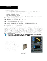
Garmin GDL 69, Pilot'S Manual
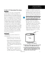
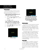
The Garmin GDL 69 is a cutting-edge aviation device that seamlessly integrates with your aircraft's avionics system. With its innovative features and advanced technology, it is essential to have the Activation Instructions manual to ensure proper setup and utilization. Download this manual for free from our website to maximize the benefits of your Garmin GDL 69.
Share
Download


Reviews:
No comments