
Summary of Contents for GDL 69
Page 1: ...190 00355 02 June 2006 Revision E GDL 69 69A Installation Manual ...
Page 2: ...This Page Intentionally Left Blank ...
Page 69: ......
Page 70: ......
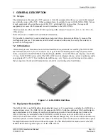
The Garmin GDL 69 is a cutting-edge aviation device that seamlessly integrates with your aircraft's avionics system. With its innovative features and advanced technology, it is essential to have the Activation Instructions manual to ensure proper setup and utilization. Download this manual for free from our website to maximize the benefits of your Garmin GDL 69.
Page 1: ...190 00355 02 June 2006 Revision E GDL 69 69A Installation Manual ...
Page 2: ...This Page Intentionally Left Blank ...
Page 69: ......
Page 70: ......


