background image

190-00303-05

December, 2012

Revision Y

GIA 63

Installation Manual

Summary of Contents for GIA 63

Page 1: ...190 00303 05 December 2012 Revision Y GIA 63 Installation Manual ...

Page 2: ...nical Support Line Toll Free 888 606 5482 www garmin com Garmin Europe Ltd Liberty House Bulls Copse Road Hounsdown Business Park Southampton SO40 9RB UK Telephone 44 0 8708501241 RECORD OF REVISIONS Revision Revision Date Description A 11 15 04 Production Release B 3 16 05 Updated pinout list removed EQF and ETSO 2C37e deviation C 6 23 05 Added additional interconnects TSO C9c and TSO C52b D 10 2...

Page 3: ... Section Number Description of Change Y 1 24 1 6 5 Added CLD part number 1 28 1 6 6 1 34 1 6 8 1 36 1 6 8 Corrected TSO C169a class Section Page Range Table of Contents i viii Section 1 1 1 1 48 Section 2 2 1 2 18 Section 3 3 1 3 8 Section 4 4 1 4 40 Section 5 5 1 5 6 Appendix A A 1 A 4 Appendix B B 1 B 6 Appendix C C 1 C 7 ...

Page 4: ...rt license The preceding statement is required to be included on any and all reproductions in whole or in part of this manual DEFINITIONS OF WARNINGS CAUTIONS AND NOTES WARNING Warnings are used to bring to the installer s immediate attention that not only damage to the equipment but personal injury may occur if the instruction is disregarded CAUTION Cautions are used to alert the individual that ...

Page 5: ...HANTABILITY OR FITNESS FOR A PARTICULAR PURPOSE STATUTORY OR OTHERWISE THIS WARRANTY GIVES YOU SPECIFIC LEGAL RIGHTS WHICH MAY VARY FROM STATE TO STATE IN NO EVENT SHALL GARMIN BE LIABLE FOR ANY INCIDENTAL SPECIAL INDIRECT OR CONSEQUENTIAL DAMAGES WHETHER RESULTING FROM THE USE MISUSE OR INABILITY TO USE THE PRODUCT OR FROM DEFECTS IN THE PRODUCT SOME STATES DO NOT ALLOW THE EXCLUSION OF INCIDENTA...

Page 6: ...quirements 2 12 2 7 GIA 63W and GIA 63H Minimum Installation Requirements 2 13 2 8 Mounting Requirements 2 14 3 INSTALLATION PROCEDURE 3 1 3 1 Unpacking Unit 3 1 3 2 Wiring Harness Installation 3 2 3 3 Antenna Installation 3 3 3 4 Cable Installation 3 3 3 5 Backshell Assembly 3 4 3 6 Unit Installation 3 4 3 7 Post Installation Configuration Checkout 3 5 3 8 Continued Airworthiness 3 6 4 SYSTEM INT...

Page 7: ...ING INSTRUCTIONS A 1 A 1 Introduction A 1 A 2 Determining Current Boot Block A 1 A 3 Loading Boot Block Version 4 01 A 2 A 4 Loading GIA Main Software only if GIA main software was cancelled in Section A 2 A 3 Appendix B OUTLINE AND INSTALLATION DRAWINGS B 1 Appendix C INTERCONNECT DRAWINGS C 1 ...

Page 8: ...ww garmin com using their Garmin provided user name and password GIA 63 P N 011 00781 00 011 00781 01 HARDWARE MOD LEVEL HISTORY APPLICABLE LRU PART NUMBER MOD LEVEL SERVICE BULLETIN NUMBER SERVICE BULLETIN DATE PURPOSE OF MODIFICATION 011 00781 00 1 0416 9 13 2004 This modification consists of modifying the voice alert audio output circuit enabling it to power down when not in use 2 0418 9 8 2004...

Page 9: ...nge without notice Authorized Garmin Sales and Service Centers are encouraged to access the most up to date bulletin and advisory information on the Garmin Dealer Resource web site at www garmin com using their Garmin provided user name and password GIA 63W GIA 63H P N 011 01105 XX HARDWARE MOD LEVEL HISTORY APPLICABLE LRU PART NUMBER MOD LEVEL SERVICE BULLETIN NUMBER SERVICE BULLETIN DATE PURPOSE...

Page 10: ...GIA 63 Installation Manual 190 00303 05 Page viii Rev Y This page intentionally left blank ...

Page 11: ...a Ethernet high speed data bus HSDB and with other LRUs using RS 232 RS 485 422 and ARINC 429 All configuration is done through the GDU The GIA 63 X contains the following sub assemblies A main processor that interfaces with all LRUs in the G1000 sub system and performs calculations for the GFC 700 autopilot if equipped A twelve channel parallel GPS receiver that simultaneously tracks and uses up ...

Page 12: ... outputs 1 VOR ILS ARINC 429 input 1 VOR ILS ARINC 429 output 5 RS 485 input output channels any two RS 485 channels can be configured to form a single RS 422 channel 8 RS 232 input output channels 41 Discrete inputs 14 Discrete outputs 24 Annunciator outputs 1 3 2 Additional Interfaces The GIA 63 X can provide interfaces for the following additional equipment Autopilot Altitude encoder serializer...

Page 13: ...inches 97 3 mm Modular Rack Height 7 26 inches 184 4 mm Standalone Rack Width 3 88 inches 98 5 mm Standalone Rack Height 6 91 inches 175 5 mm Depth w connectors Modular and Standalone 10 20 inches 259 1 mm Unit Weight 011 00781 0X 5 3 lbs 2 40 kg 011 01105 0X 1X 2X 5 3 lbs 2 40 kg 011 01105 4X 5 5 lbs 2 49 kg Modular Rack Weight w Back Plate 1 0 lbs 0 45 kg Standalone Rack Weight w Back Plate 1 3 ...

Page 14: ...tailed specifications see the Environmental Qualification Form Table 1 2 GIA 63 X General Specifications Characteristic Specification Operating Temperature Range 40 C to 65 C For more details see Environmental Qualification Form Humidity 95 non condensing Altitude Range 1 500 ft to 50 000 ft ...

Page 15: ... at 4 6 VDC Table 1 4 GIA 63W and GIA 63H GPS Specifications Characteristic Specification Number of channels 15 12 GPS and 3 GPS WAAS SBAS Frequency 1575 42 MHz L1 C A code Sensitivity acquisition 116 dBm to 134 5 dBm GPS 116 dBm to 134 5 dBm WAAS Sensitivity drop lock 144 dBm Lat Long position accuracy 1 25 meter RMS horizontal 2 meter vertical with WAAS Velocity 1000 knots maximum above 60 000 f...

Page 16: ... channeling 60 dB BW is less than 7 37 kHz for 8 33 kHz channeling Spurious Response Greater than 80 dB Transmitter Power At Least 16 watts when Vin 28 VDC At least 10 watts when Vin 14 VDC 011 01105 2X and 011 01105 3X only Transmitter Duty Cycle Recommended 10 maximum Modulation Capability The modulation shall not be less than 70 and not greater than 99 9 with a standard modulator signal applied...

Page 17: ...ulations d When the level of a standard VOR deviation test signal produces less than a 50 of standard deflection AGC Characteristics From 99 dBm to 13 dBm input of a Standard VOR Audio Test Signal audio output levels shall not vary more than 3 dB Spurious Response Greater than 60 dB VOR OBS Bearing Accuracy The bearing information as presented to the pilot shall not have an error in excess of 2 7 ...

Page 18: ... 150 Hz modulation e In the absence of RF AGC Characteristics From 99 dBm and 13 dBm input of a Standard VOR Audio Test Signal audio output levels shall not vary more than 3 dB Selectivity 6 dB BW is greater than 9 kHz 69 dB BW is less than 36 kHz Standard Deflection a With a standard deflection FLY LEFT condition 90 Hz dominant the output shall be 90 mV 9 mV b With a standard deflection FLY RIGHT...

Page 19: ...d deviation test signal produces 50 or less of standard deflection of the deviation indicator b In the absence of 150 Hz modulation c In the absence of 90 Hz modulation d In the absence of both 90 Hz and 150 Hz modulation e In the absence of RF Table 1 9 GIA 63 X Power Specifications Characteristic Specification Input Voltage Range For P601 011 00781 0X and 011 01105 0X 28 Vdc 011 01105 2X 3X 14 2...

Page 20: ...rt 28 Vdc COMs Table 1 10 GIA 63 X Power Interrupt Unit Name Unit Part Number Mod Status Long Term Power Interrupt Category Per RTCA DO 160 GIA 63 011 00781 00 4 A 200mS 0 1 2 3 B 50mS 011 00781 01 1 A 200mS 0 B 50mS GIA 63W 011 01105 00 1 A 200mS 0 B 50mS 011 01105 01 0 A 200mS 011 01105 20 0 A 200mS 011 01105 40 0 A 200mS GIA 63H 011 01105 30 0 A 200mS Refer to Mod Status Table in front of manua...

Page 21: ...VDC Operation 011 01105 2X and 3X only Emission Type 6K00A3E 25 kHz Channel Spacing Mode 5K6A3E 8 33 kHz Channel Spacing Mode 011 01105 2X 3X 4X only Frequency of Operation 118 000 136 992 MHz If an aircraft license is required make application for a license on FCC form 404 application for Aircraft Radio Station License The FCC also has a fax on demand service to provide forms by fax The GIA 63 X ...

Page 22: ... meeting the requirements of 14 CFR 91 227 when installed in accordance with Garmin s installation instructions NOTE It is the installer s responsibility to ensure the ADS B Out system is compliant with AC 20 165 and to ensure compatibility between the GIA 63 X and the ADS B Out equipment See 14 CFR 91 227 ADS B Out Compatibility Equipment Garmin part number 190 01533 00 for compatible equipment s...

Page 23: ...0190 04 006 B0082 02 006 C0046 006 C0044 006 C0047 006 C0039 01 006 C0053 00 VHF COM Transmitter TSO C37d ETSO 2C37e Class 3 and 5 All 006 B0190 except 006 B0190 00 through 006 B0190 04 All 006 B0081 0 except 006 B0081 00 through 006 B0081 04 006 C0046 006 C0044 006 C0047 006 C0039 01 VHF COM Receiver TSO C38d ETSO 2C38e Class C and E All 006 B0190 except 006 B0190 00 through 006 B0190 04 All 006 ...

Page 24: ...0039 01 GPS TSO C129a ETSO C129a Class A1 All 006 B0190 except 006 B0190 00 through 006 B0190 04 006 B0093 00 006 B0093 01 006 C0046 006 C0044 006 C0047 TAWS TSO C151b Class A and B All 006 B0190 except 006 B0190 00 through 006 B0190 29 006 C0046 006 C0044 ETSO C151a Class B 006 C0047 006 C0039 01 Table 1 11 GIA 63 TSO ETSO Compliance Function TSO ETSO Category Applicable LRU SW Part Numbers Appli...

Page 25: ...B and DO 178B instead of DO 178A TSO C37d 1 Garmin was granted a deviation from TSO C37d to use DO 160D Change 3 instead of DO 160B and DO 178B instead of DO 178A 2 Garmin was granted a deviation from TSO C37d paragraph a 1 to allow using RTCA document DO 186a Change 2 instead of RTCA document DO 186 to specify minimum performance standards 3 Garmin was granted a deviation from TSO C37d by allowin...

Page 26: ... All data bits in subframe 1 2 or 3 are 0 s 8 Garmin was granted a deviation from TSO C129a to change the requirement in paragraph a 7 ii to match the WAAS TSO C145a and DO 229 requirements for Power input testing ETSO C129a 1 Garmin was granted a deviation from ED 72A 3 2 2 1 f list item 3 and 3 2 2 4 j 4 to eliminate the annunciation for pending CDI scale change 3 0 nm from the FAF 2 Garmin was ...

Page 27: ...2 Glideslope Receiver TSO C34e ETSO 2C34f All 006 B0544 1 through 006 B0544 4 and all 006 B0544 B except 006 B0544 BA through 006 B0544 BB All 006 B0083 0 except 006 B0083 00 through 006 B0083 01 All 006 C0084 0 except 006 C0084 00 006 C0072 0 006 C0085 0 All 006 C0039 0 except 006 C0039 00 through 006 C0039 02 Localizer Receiver TSO C36e ETSO 2C36f Class A 006 B0544 1 through 006 B0544 4 and all ...

Page 28: ...cept 006 C0053 00 Flight Director Equipment TSO C52b ETSO C52b All 006 B0544 1 through 006 B0544 4 and all 006 B0544 B except 006 B0544 BA through 006 B0544 BB All 006 C0084 0 except 006 C0084 00 006 C0072 0 006 C0085 0 All 006 C0039 0 except 006 C0039 00 through 006 C0039 02 Stall Warning Instruments TSO C54 Type II All 006 B0544 4 and all 006 B0544 B except 006 B0544 BA through 006 B0544 BB All ...

Page 29: ...44 BA through 006 B0544 BB All 006 B0339 0 except 006 B0339 00 through 006 B0339 03 All 006 C0084 0 except 006 C0084 00 006 C0072 0 006 C0085 0 TAWS TSO C151b ETSO C151a Class B All 006 B0544 1 through 006 B0544 2 and all 006 B0544 B except 006 B0544 BA through 006 B0544 BB All 006 C0084 0 except 006 C0084 00 006 C0072 0 006 C0085 0 All 006 C0039 0 except 006 C0039 00 through 006 C0039 02 TSO C151...

Page 30: ...06 B0544 B except 006 B0544 BA through 006 B0544 BB All 006 B0081 0 except 006 B0081 00 through 006 B0081 04 All 006 C0084 0 except 006 C0084 00 006 C0072 0 006 C0085 0 All 006 C0039 0 except 006 C0039 00 through 006 C0039 02 GIA63W ARINC output labels 310 and 311 are not to be used as navigation data per RTCA DO 229c Table 1 13 GIA 63W TSO ETSO Compliance Function TSO ETSO Category Applicable LRU...

Page 31: ...on from ETSO 2C34f to use DO 160E instead of DO 160D TSO C36e 1 Garmin was granted a deviation from TSO C36e to use DO 160E instead of DO 160B and DO 178B instead of DO 178A ETSO 2C36f 1 Garmin was granted a deviation from ETSO 2C36f to use DO 160E instead of DO 160D 2 Garmin was granted a deviation from ETSO 2C36f to use ED 46B amendment 2 in addition to ED 46B ETSO 2C37e 1 Garmin was granted a d...

Page 32: ...10 second reacquisition time ETSO C145 1 Garmin was granted a deviation from ETSO C145 to use DO 160E instead of DO 160D 2 Garmin was granted a deviation from ETSO C145 to use DO 229C instead of DO 229A 3 Garmin was granted a deviation from DO 229C paragraphs 2 1 1 10 2 1 1 7 2 1 1 8 1 2 1 1 8 2 2 1 1 9 2 1 2 1 2 1 3 1 2 1 4 1 4 2 1 4 1 5 and 2 1 5 1 in the form of an operational limitation to ach...

Page 33: ...appliance approvals 3 Garmin was granted a deviation to TSO C169 paragraph 4 e requirement to mark DEV after the TSO number on the equipment Garmin will mark as follows as TSOC169 is not the primary TSO and the Install Manual contains all of the TSO C169 information including deviations TSO C145a See Install Manual for additional appliance approvals 4 Garmin was granted to deviate from TSO C169 by...

Page 34: ...0084 0 except 006 C0084 00 006 C0072 0 006 C0085 0 Glideslope Receiver TSO C34e ETSO 2C34f All 006 B0544 3 through 006 B0544 4 except 006 B0544 30 through 006 B0544 34 and all 006 B0544 B except 006 B0544 BA through 006 B0544 BD All 006 B0082 1 except 006 B0082 10 All 006 C0084 0 except 006 C0084 00 006 C0072 0 006 C0085 0 006 C0124 0 Localizer Receiver TSO C36e ETSO 2C36f Class A All 006 B0544 3 ...

Page 35: ...or Equipment TSO C52b ETSO C52b All 006 B0544 3 through 006 B0544 4 except 006 B0544 30 through 006 B0544 34 and all 006 B0544 B except 006 B0544 BA through 006 B0544 BD All 006 C0084 0 except 006 C0084 00 006 C0072 0 006 C0085 0 Stall Warning Instruments TSO C54 Type II All 006 B0544 4 and all 006 B0544 B except 006 B0544 BA through 006 B0544 BD All 006 C0084 0 except 006 C0084 00 006 C0072 0 006...

Page 36: ...c All 006 B0544 3 through 006 B0544 4 except 006 B0544 30 through 006 B0544 34 and all 006 B0544 B except 006 B0544 BA through 006 B0544 BD All 006 C0084 0 except 006 C0084 00 006 C0072 0 006 C0085 0 Table 1 15 GIA 63W Updated NAV COM TSO ETSO Compliance Function TSO ETSO Category Applicable LRU SW Part Numbers Applicable CLD Part Numbers ...

Page 37: ...544 30 through 006 B0544 34 and all 006 B0544 B except 006 B0544 BA through 006 B0544 BD All 006 C0084 0 except 006 C0084 00 006 C0072 0 006 C0085 0 VHF Radio Communications Transceiver Equipment TSO C169a Equivalent to ETSO 2C37e ETSO 2C38e Class 3 4 5 and 6 transmitter Class C and E receiver All 006 B0544 3 through 006 B0544 4 except 006 B0544 30 through 006 B0544 34 and all 006 B0544 B except 0...

Page 38: ...6 C0084 00 006 C0072 0 006 C0085 0 Glideslope Receiver TSO C34e ETSO 2C34f All 006 B0544 3 through 006 B0544 4 except 006 B0544 30 through 006 B0544 35 and all 006 B0544 B except 006 B0544 BA through 006 B0544 BD All 006 B0082 1 except 006 B0082 10 All 006 C0084 0 except 006 C0084 00 006 C0072 0 006 C0085 0 006 C0124 0 Localizer Receiver TSO C36e ETSO 2C36f Class A All 006 B0544 3 through 006 B054...

Page 39: ...t Director Equipment TSO C52b ETSO C52b All 006 B0544 3 through 006 B0544 4 except 006 B0544 30 through 006 B0544 35 and all 006 B0544 B except 006 B0544 BA through 006 B0544 BD All 006 C0084 0 except 006 C0084 00 006 C0072 0 006 C0085 0 Stall Warning Instruments TSO C54 Type II All 006 B0544 4 and all 006 B0544 B except 006 B0544 BA through 006 B0544 BD All 006 C0084 0 except 006 C0084 00 006 C00...

Page 40: ...em TSO C145a ETSO C145 Class 3 All 006 B0544 3 through 006 B0544 4 except 006 B0544 30 through 006 B0544 35 and all 006 B0544 B except 006 B0544 BA through 006 B0544 BD All 006 B0339 0 except 006 B0339 00 through 006 B0339 03 All 006 C0084 0 except 006 C0084 00 006 C0072 0 006 C0085 0 TAWS TSO C151b ETSO C151b Class A and B All 006 B0544 3 through 006 B0544 4 except 006 B0544 30 through 006 B0544 ...

Page 41: ... 3 through 006 B0544 4 except 006 B0544 30 through 006 B0544 35 and all 006 B0544 B except 006 B0544 BA through 006 B0544 BD 006 B0081 1 All 006 C0084 0 except 006 C0084 00 006 C0072 0 006 C0085 0 GIA 63H ARINC output labels 310 and 311 are not to be used as navigation data per RTCA DO 229c Table 1 16 GIA 63H TSO ETSO Compliance Function TSO ETSO Category Applicable LRU SW Part Numbers Applicable ...

Page 42: ...Garmin was granted a deviation from ETSO 2C34f to use DO 160E instead of DO 160D TSO C36e 1 Garmin was granted a deviation from TSO C36e to use DO 160E instead of DO 160B and DO 178B instead of DO 178A ETSO 2C36f 1 Garmin was granted a deviation from ETSO 2C36f to use DO 160E instead of DO 160D 2 Garmin was granted a deviation from ETSO 2C36f to use ED 46B amendment 2 in addition to ED 46B ETSO 2C...

Page 43: ...e effective mask angle through operational limitations to a level commensurate with test conditions used in the original TSO qualification tests 4 The ability to use 128 dBmic as the minimum GPS satellite signal in space for the purpose of assessing the operational limitation 5 The ability to use 128 dBmic as the minimum SBAS satellite signal in space for the purpose of assessing the operational l...

Page 44: ...544 BD All 006 B0082 1 except 006 B0082 10 All 006 C0084 0 except 006 C0084 00 006 C0072 0 006 C0085 0 006 C0124 0 Localizer Receiver TSO C36e Class A All 006 B0544 4 and all 006 B0544 B except 006 B0544 BA through 006 B0544 BD All 006 B0082 1 except 006 B0082 10 All 006 C0084 0 except 006 C0084 00 006 C0072 0 006 C0085 0 006 C0124 0 VOR Receiver TSO C40c All 006 B0544 4 and all 006 B0544 B except...

Page 45: ...ept 006 C0084 00 006 C0072 0 006 C0085 0 Ground Proximity Warning Glide Slope Deviation Alerting Equipment TSO C92c All 006 B0544 4 and all 006 B0544 B except 006 B0544 BA through 006 B0544 BD All 006 C0084 0 except 006 C0084 00 006 C0072 0 006 C0085 0 Table 1 18 GIA 63W with Enhanced COM TSO ETSO Compliance Function TSO ETSO Category Applicable LRU SW Part Numbers Applicable CLD Part Numbers ...

Page 46: ...Equipment TSO C160 Architecture Class Z All 006 B0544 4 and all 006 B0544 B except 006 B0544 BA through 006 B0544 BD All 006 C0084 0 except 006 C0084 00 006 C0072 0 006 C0085 0 VHF Radio Communications Transceiver Equipment TSO C169a Class 3 and 5 transmitter Class C and E receiver All 006 B0544 4 and all 006 B0544 B except 006 B0544 BA through 006 B0544 BD All 006 B0081 1 except 006 B0081 10 and ...

Page 47: ... TSO C36e 1 Garmin was granted a deviation from TSO C36e to use DO 160E instead of DO 160B and DO 178B instead of DO 178A TSO C40c 1 Garmin was granted a deviation from TSO C40c to use DO 160E instead of DO 160B and DO 178B instead of DO 178A TSO C52b 1 Garmin was granted a deviation from SAE AS 8008 paragraph 3 6 to limit flight director operation to attitudes considered safe for the certified ai...

Page 48: ...ned in RTCA DO 280B volume 2 and the PDRs defined in EUROCONTROL SPEC 0116 in order to reflect guidance provided by AC 20 140A 8 Garmin was granted a deviation from RTCA DO 224B paragraph 3 2 2 4 2 3 1 to interpret that an air ground bit set to 0 indicates that the transmitting station is airborne This deviation is required to match the interpretation of the air ground bit described in paragraph 5...

Page 49: ...manual stating that the appli ance must not be installed in areas where fluid contamination could be commonly encountered if this category is not claimed in the unit environmental qualification form 3 Garmin was granted a deviation from RTCA DO 186B sections 2 4 7 to interpret Waterproofness RTCA DO 160E Section 10 0 testing as When Required in order to resolve a discrepancy between guidance provi...

Page 50: ...lternate means of navigation appropriate to the flight with the exception of oceanic and remote operations 2 For flight planning purposes if an alternate airport is required it must have an approved instrument approach procedure other than GPS or RNAV that is anticipated to be operational and available at the estimated time of arrival All equipment required for this procedure must be installed and...

Page 51: ...on approach operations including those approaches titled GPS or GPS and RNAV GPS approaches The Garmin GNSS navigation system is approved for approach procedures with vertical guidance including LPV and LNAV VNAV within the U S National Airspace System The Garmin GNSS navigation system complies with the equipment requirements of AC 90 105 and meets the equipment performance and functional requirem...

Page 52: ... or GIA 63Hs and two or more ETSO 146 Class 3 or ETSO C146c Class 3 TSO C146a Class 3 or TSO C146c Class 3 approved Garmin GDU 1XXX Display Units The Garmin GNSS navigation system complies with the equipment requirements for P RNAV and B RNAV RNAV 5 operations in accordance with AC 90 96A CHG 1 and JAA TGL 10 Rev 1 This does not constitute an operational approval Garmin International holds an FAA ...

Page 53: ...program or Europe s AUGER GPS RAIM Prediction Tool at http augur ecacnav com augur app home For other areas use the Garmin WFDE Prediction program This requirement is not necessary if SBAS coverage is confirmed to be available along the entire route of flight The route planning and WFDE prediction program may be downloaded from the Garmin website on the internet For information on using the WFDE P...

Page 54: ...ing is prohibited GPS or GPS and RNAV GPS instrument approaches using the Garmin navigation systems are prohibited unless the flight crew verifies and uses the current Navigation database GPS based instrument approaches must be flown in accordance with an approved instrument approach procedure that is loaded from the Navigation database Not all published Instrument Approach Procedures IAP are in t...

Page 55: ...DO 208 Class A1 GPS RTCA DO 186a Class 3 and 5 VHF Com Transmitter RTCA DO 186a Class C and E VHF Com Receiver RTCA DO 196 VOR Receiver RTCA DO 195 Class A Localizer Receiver RTCA DO 192 Glideslope Receiver ICAO Annex 10 Volume III EUROCAE ED 23B VHF Com Transceiver ICAO Annex 10 Volume I EUROCAE ED 22B VOR Receiver ICAO Annex 10 Volume I EUROCAE ED 46B Localizer Receiver EUROCAE ED 47B Glideslope...

Page 56: ... 3 and later All other GIA software part numbers support RTCA DO 178B Levels B C and D only 011 01105 0X only RTCA DO 254 Level A and C CLD devices RTCA DO 229c Class Beta 3 GPS WAAS RTCA DO 186a Class 3 and 5 VHF Com Transmitter RTCA DO 186a Class C and E VHF Com Receiver ICAO Annex 10 Volume III EUROCAE ED 23B VHF Com Transceiver 011 01105 2X and 011 01105 3X only RTCA DO 254 Level A CLD devices...

Page 57: ...n Instructions II A258005 Comant CI 2580 200 Installation Instructions II A42803 Comant CI 428 410 Installation Instructions II A42809 Comant CI 428 200 Installation Instructions II A272803 Comant CI 2728 410 Installation Instructions II A272806 Comant CI 2728 200 Installation Instructions 190 00848 00 GA 35 GA 36 and GA 37 Antenna Installation Instructions 190 00355 02 GDL 69 69A Installation Man...

Page 58: ...GIA 63 Installation Manual 190 00303 05 Page 1 48 Rev Y This page intentionally left blank ...

Page 59: ...or further details on the mechanical aspects For installation in an aircraft using the remote mounted standalone rack refer to Appendix B for rack drawings and dimensions 2 1 1 Unit Configurations The GIA 63 X is only available as a single unit under the following part numbers Table 2 1 GIA 63 X Part Numbers Item Garmin P N GIA 63 Unit Only 011 00781 00 010 00335 00 GIA 63 ETSO Unit Only 011 00781...

Page 60: ...r GIA 63H Helicopter Install Rack 115 00426 00 115 01239 00 011 02425 00 G1000 Rack Nutplate Kit Modular Rack Only 011 00915 01 preferred or 011 01148 01 GIA 63 W Back Plate Modular and Standalone 011 00963 00 GIA 63H Back Plate Helicopter 011 00963 01 GIA 63 X Connector Kit w Spider 011 01000 00 GIA 63 X Connector Kit w Shield Block 011 01000 01 GIA 63 X Connector Kit IF Seal 011 01000 03 Only th...

Page 61: ...ic with transistorized pre amp Hardware 6 32 x 100 Flathead SS Screw MS24693 AN507R or other approved fastener 4 ea for horizontal mounting of the standalone rack Hardware 8 32 Panhead Machine Screw MS35206 AN526 or other approved fastener 4 ea for vertical mounting of the standalone rack Hardware 10 32 x 100 Flathead Screw MS24694S51 or screw of same or greater strength 4 ea for mounting of the h...

Page 62: ...6GW TNCF 000 RG 27 NM 013 00244 00 Garmin 013 00244 00 GA 37 FIS WAAS Antenna 6 Screw Mount ARINC 743 Footprint TNC Yes Aero Antenna AT2300 126GW TNCF 000 RG 27 NM 013 00245 00 Garmin 013 00245 00 Comant 2580 200 WAAS and COM Antenna 6 8 Screw Mount Teardrop Footprint 2 BNC TNC 5 Yes Comant CI 2580 200 N A Comant 2580 410 FIS WAAS COM Antenna 6 8 CI 2580 410 Comant 428 200 WAAS Antenna 6 8 Screw M...

Page 63: ...pecification for Garmin s GPS WAAS Receiver System Antenna 004 00287 00 by communicating the requirement to the supplier and obtaining a certificate of compliance to 004 00287 00 from the supplier An antenna that complies only with TSO C144 requirements is not adequate for this installation Other TSO C144 antennas may meet the installation requirements of the GIA 63W and GIA 63H Contact Garmin to ...

Page 64: ...enna installation engineering data 4 Locate an appropriate consultant FAA DER by reviewing the FAA Consultant DER Directory which can be found at the FAA Designee and Delegation web page 5 Contact an aviation industry organization such as the Aircraft Electronics Association for assistance 2 2 2 GPS Antenna Location The GPS antenna is a key element in the overall system performance and integrity f...

Page 65: ...fer ence check in Post Installation Checkout procedures can verify the degradation of GPS in the presence of interference signals If an EMC check reveals unacceptable interference insert a GPS notch filter in line with the offending VHF COM or the re radiating ELT transmitter NOTE The separation requirement does not apply to GPS and COM combination antennas provided the antenna model is TSO author...

Page 66: ...GIA 63 Installation Manual 190 00303 05 Page 2 8 Rev Y Figure 2 1 shows the recommended placement of antennas Figure 2 1 GPS Antenna Considerations ...

Page 67: ... GIA 63 X VOR LOC antenna should be well removed from all projections engines and propellers It should have a clear line of sight if possible The antenna must be mounted along the centerline of the aircraft minimizing the lateral offset 2 2 5 Glideslope Antenna Location The GIA 63 X Glideslope antenna should be well removed from all projections engines and propellers It should have a clear line of...

Page 68: ...found to be radiating the following can be done 1 Replace or clean the VHF COM rack connector to ensure good coax ground 2 Place grounding straps between the GIA 63 X unit VHF COM and a good ground 3 Shield the VHF COM wiring harness 2 3 Rack Considerations A location away from heating vents or other sources of heat generation is optimal The GIA 63 W can be mounted using the G1000 system rack The ...

Page 69: ...ld not be routed near components or cabling which are sources of electrical noise Do not route the COM antenna coax near any ADF antenna cables Route the GPS VOR LOC and Glideslope antenna cables as far as possible away from all COM transceivers and antenna cables 2 5 Cooling Air The GIA 63 X meets all TSO requirements without external cooling However as with all electronic equipment lower operati...

Page 70: ...r or from the GDU PFD MFD via Ethernet HSDB HSI CDI Indicator or GDU This device displays Nav Flag Left Right To From Glideslope Flag and Up Down Qualified GPS Antenna This antenna must meet the following requirements 1 DO 160C Environmental Conditions The antenna shall meet the environmental conditions listed below and shall conform to the test requirements of RTCA DO 160C Environmental Condition...

Page 71: ...imum 4 Mounting Requirements Cable connection BNC Female Mounting studs Four 8 32 UNC 2A studs 0 50 long 2 7 GIA 63W and GIA 63H Minimum Installation Requirements Below is a list of required devices for TSO C145a Class 3 or TSO C145c Class 3 certification Manual Course Device This device delivers the manual course select to the GIA 63W or GIA 63H which is required for the VOR receiver and optional...

Page 72: ...ntered unless the applicable unit EQF indicates that the unit has claimed the appropriate RTCA DO 160 categories for these environments 2 8 2 Modular Rack Considerations Figure 2 2 and Figure B 2 show the GIA 63 W G1000 modular rack The modular rack is fastened to the main system rack using the nutplate kit listed in Section 2 1 2 Refer to Figure B 2 for nutplate placement locations Figure B 1 giv...

Page 73: ...ad screws MS35206 AN526 or other approved fastener It can also be mounted horizontally using four 6 32 100 counter sunk flathead screws MS24693 AN507R or other approved fastener Ensure that the GIA 63 W chassis has a ground path to the airframe by having at least one mounting screw in contact with the airframe Figure 2 4 and Figure B 6 show the stand alone rack used for the GIA 63H installation Fi...

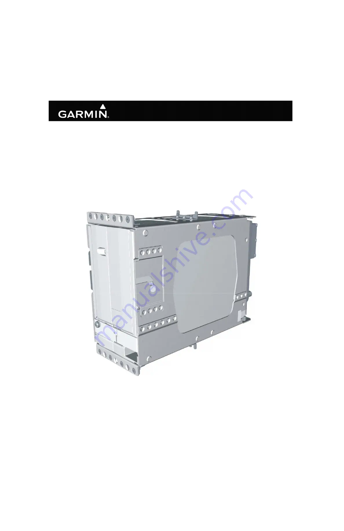
Page 74: ...GIA 63 Installation Manual 190 00303 05 Page 2 16 Rev Y Figure 2 4 GIA 63H Standalone Rack ...

Page 75: ...190 00303 05 GIA 63 Installation Manual Rev Y Page 2 17 Figure 2 5 GIA 63 W Standalone Rack Suggested Mounting Locations ...

Page 76: ...GIA 63 Installation Manual 190 00303 05 Page 2 18 Rev Y This page intentionally left blank ...

Page 77: ...s damaged notify the carrier and file a claim To justify a claim save the original shipping container and all packing materials Do not return the unit to Garmin until the carrier has authorized the claim Retain the original shipping containers for storage If the original containers are not available a separate cardboard container should be prepared that is large enough to accommodate sufficient pa...

Page 78: ...t may also be necessary to push the pin out from the face of the connector when using an extractor due to the absence of the wire A new contact must be used when reassembling the connector 3 For applications using 16 AWG wire contact Garmin for information regarding connector crimp positioner tooling Table 3 1 Pin Contact Part Numbers Manufacturer 78 pin connectors P603 605 606 62 pin connectors P...

Page 79: ...stallation 1 Route the coaxial cable to the rack location keeping in mind the recommendations of Section 2 Secure the cable in accordance with good aviation practice 2 Trim the coaxial cable to the desired length and install the BNC connector 330 00087 00 per the cabling instructions on Figure 3 1 If the connector is provided by the installer follow the connector manufacturer s instructions for ca...

Page 80: ...nect backshell connectors to the rear plate using the provided screws 3 Mount the unit rack to the main system rack or other suitable mounting location using the nutplates provided for the modular rack or appropriate hardware from Section 2 1 3 for the standalone rack 4 Assemble the NAV and Main rear plates into the GIA 63 W unit rack 5 Carefully slide the GIA 63 W into the rack Ensure that the or...

Page 81: ...nstall screw Tighten the screw to the torque specified in Appendix B CAUTION Do not use excessive force when inserting the GIA 63H into the rack This may cause damage to the connectors unit and or unit rack If excessive resistance is felt during installation stop Remove the GIA 63H and identify the source of resistance The rear plates are designed to float in the unit rack Check to ensure the rear...

Page 82: ...wer interrupt Category A 200mS one of the following two actions must be taken to ensure backup time is adequate Comply with the applicable GIA 63 X Mod Status refer to Table 3 3 Or Perform the power interrupt annual inspection as described in Section 3 8 1 Table 3 3 Long Term Power Interrupt Category A 200 mS Mod Status Unit Unit Part Number Long Term Power Interrupt Category A 200 mS Mod Status G...

Page 83: ...GIA s on for 10 minutes 4 Remove power from both GIA s 5 Wait 30 seconds 6 Apply power to both GIA s 7 Place the G1000 in Configuration mode by holding the ENT key on the GDU s while applying power 8 Using the FMS knob go to the GIA STATUS page Figure 3 2 on the PFD 9 Verify the GIA 1 BKUP CAPS light is green If the BKUP CAPS light is red replace GIA 1 with a unit of mod status indicated in Table ...

Page 84: ...GIA 63 Installation Manual 190 00303 05 Page 3 8 Rev Y This page intentionally left blank ...

Page 85: ...LY Out 2 RESERVED 3 RESERVED 4 COM MIC KEY In 5 RESERVED 6 RESERVED 7 COM MIC AUDIO IN HI In 8 COM MIC AUDIO IN LO GROUND 9 COM 500Ω AUDIO OUT HI Out 10 COM 500Ω AUDIO OUT LO Out 11 TRANSMIT INTERLOCK In 12 COM REMOTE TRANSFER In 13 COM DIGITAL AUDIO OUT Out 14 ON SIDE COM MIC DIGITAL AUDIO IN In 15 SIGNAL GROUND 16 COM REMOTE POWER OFF In 17 AIRCRAFT POWER 1 In 18 SPARE CROSS SIDE COM MIC DIGITAL...

Page 86: ...ARE 25 AIRCRAFT POWER 2 In 26 SPARE 27 AIRCRAFT POWER 2 In 28 RESERVED 29 RESERVED 30 POWER GROUND 31 POWER GROUND 32 RESERVED 33 RESERVED 34 COM SECONDARY TX INTERLOCK 011 01105 4X ONLY In 35 RESERVED 36 RESERVED 37 RESERVED 38 RESERVED 39 RESERVED 40 RESERVED 41 RESERVED 42 RESERVED 43 POWER GROUND 44 POWER GROUND Table 4 1 P601 COM Pin List Pin Pin Name I O ...

Page 87: ...X ONLY Out 7 RESERVED 8 VOR LOC COMPOSITE OUT Out 9 VOR OBS ROTOR C Out 10 VOR OBS ROTOR H GROUND 11 VOR OBS STATOR E VOR LOC COMMON Out VOR OBS STATOR E NAV COMMON 011 01105 2X 3X 4X ONLY Out 12 VOR OBS STATOR F In 13 VOR OBS STATOR D In 14 VOR OBS STATOR G VOR LOC COMMON Out VOR OBS STATOR G NAV COMMON 011 01105 2X 3X 4X ONLY Out 15 VOR LOC SUPERFLAG Out 16 VOR LOC 500Ω AUDIO OUT HI Out 17 VOR L...

Page 88: ...ARALLEL DME 1 MHZ D Out 34 GLIDESLOPE UP Out 35 VOR ILS ARINC 429 IN B In 36 VOR ILS ARINC 429 IN A In 37 PARALLEL DME 100 KHZ A Out 38 GLIDESLOPE SUPERFLAG Out 39 PARALLEL DME 100 KHZ B Out 40 PARALLEL DME 100 KHZ C Out 41 DME COMMON In 42 PARALLEL DME 100 KHZ D Out 43 PARALLEL DME 50 KHZ Out 44 RESERVED 45 PARALLEL DME 1 MHZ A Out 46 PARALLEL DME 1 MHZ B Out 47 PARALLEL DME 1 MHZ C Out 48 RESERV...

Page 89: ...MON 011 01105 2X 3X 4X ONLY Out 54 PARALLEL DME 100KHZ E Out 55 GLIDESLOPE DOWN GLIDESLOPE COMMON Out GLIDESLOPE DOWN NAV COMMON 011 01105 2X 3X 4X ONLY Out 56 PARALLEL DME 1MHZ E Out 57 RESERVED 58 SPARE GLIDESLOPE COMPOSITE OUT 011 01105 2X 3X 4X ONLY Out 59 VOR LOC DIGITAL AUDIO OUT Out 60 SIGNAL GROUND 61 POWER GROUND 62 POWER GROUND Table 4 2 P602 VOR ILS Pin List Pin Pin Name I O ...

Page 90: ...485 4 B I O 7 RS 485 4 B I O 8 MAIN ARINC 429 IN 3 A In 9 MAIN ARINC 429 IN 3 B In 10 MAIN ARINC 429 IN 4 A In 11 MAIN ARINC 429 IN 4 B In 12 MAIN ARINC 429 IN 5 A In 13 MAIN ARINC 429 IN 5 B In 14 MAIN ARINC 429 IN 6 A In 15 MAIN ARINC 429 IN 6 B In 16 MAIN ARINC 429 IN 7 A In 17 MAIN ARINC 429 IN 7 B In 18 MAIN ARINC 429 IN 8 A In 19 MAIN ARINC 429 IN 8 B In 20 CAN BUS 1 HI I O 21 RESERVED 22 CA...

Page 91: ...S 485 5 A RS 422 OUT A I O 37 RS 485 5 B RS 422 OUT B I O 38 RESERVED 39 CAN BUS 2 TERMINATION 40 RESERVED 41 MAIN RS 232 IN 1 In 42 SIGNAL GROUND 43 MAIN RS 232 OUT 1 Out 44 MAIN RS 232 IN 2 In 45 SIGNAL GROUND 46 MAIN RS 232 OUT 2 Out 47 MAIN RS 232 IN 3 In 48 SIGNAL GROUND 49 MAIN RS 232 OUT 3 Out 50 MAIN RS 232 IN 4 In 51 SIGNAL GROUND 52 MAIN RS 232 OUT 4 Out 53 MAIN RS 232 IN 5 In 54 SIGNAL ...

Page 92: ...ut 63 MAIN RS 232 IN 8 In 64 SIGNAL GROUND 65 MAIN RS 232 OUT 8 Out 66 RESERVED 67 GPS PPS OUT Out 68 RESERVED 69 VOICE ALERT DIGITAL AUDIO OUT Out 70 MAIN ARINC 429 OUT 1 B Out 71 MAIN ARINC 429 OUT 1 A Out 72 MAIN ARINC 429 OUT 2 B Out 73 MAIN ARINC 429 OUT 2 A Out 74 MAIN ARINC 429 OUT 3 B Out 75 MAIN ARINC 429 OUT 3 A Out 76 ETHERNET IN A In 77 ETHERNET IN B In 78 RESERVED Table 4 3 P603 Main ...

Page 93: ... Out 4 DISCRETE IN 13 In 5 DISCRETE IN 14 In 6 ANNUNCIATE 1 Out 7 DISCRETE IN 1 In 8 DISCRETE IN 2 In 9 DISCRETE IN 3 In 10 DISCRETE IN 15 In 11 AUTOPILOT DISCONNECT IN In 12 DISCRETE IN 4 In 13 DISCRETE IN 5 In 14 DISCRETE IN 6 In 15 DISCRETE IN 16 In 16 DISCRETE IN 17 In 17 DISCRETE IN 7 In 18 DISCRETE IN 8 In 19 DISCRETE IN 9 In 20 DISCRETE IN 10 In 21 DISCRETE IN 11 In 22 GIA SYSTEM ID PROGRAM...

Page 94: ...29 ANNUNCIATE 6 Out 30 ANNUNCIATE 7 Out 31 ANNUNCIATE 8 Out 32 ANNUNCIATE 9 Out 33 ANNUNCIATE 10 Out 34 ANNUNCIATE 11 Out 35 ANNUNCIATE 12 Out 36 ANNUNCIATE 13 Out 37 ANNUNCIATE 14 Out 38 ANNUNCIATE 15 Out 39 ANNUNCIATE 16 Out 40 ANNUNCIATE 17 Out 41 ANNUNCIATE 18 Out 42 ANNUNCIATE 19 Out 43 ANNUNCIATE 20 Out 44 ANNUNCIATE 21 Out Table 4 4 P604 Main Discrete Pin List Pin Pin Name I O ...

Page 95: ...P In 9 FLIGHT DIRECTOR PITCH DOWN In 10 FLIGHT DIRECTOR ROLL RIGHT In 11 FLIGHT DIRECTOR ROLL LEFT In 12 DISCRETE IN 19A In 13 POTENTIOMETER SIGNAL IN In 14 POTENTIOMETER REF IN HI In 15 POTENTIOMETER REF IN LO In 16 DISCRETE IN 20A In 17 MAIN LATERAL DEVIATION LEFT Out 18 MAIN LATERAL DEVIATION RIGHT MAIN COMMON Out 19 MAIN LATERAL FLAG Out 20 MAIN LATERAL FLAG MAIN COMMON Out 21 SPARE 22 SPARE 2...

Page 96: ...E POWER OFF In 37 DISCRETE IN 1A In 38 DISCRETE IN 2A In 39 DISCRETE IN 3A In 40 DISCRETE IN 4A In 41 DISCRETE IN 5A In 42 DISCRETE IN 6A In 43 DISCRETE IN 7A In 44 DISCRETE IN 8A In 45 DISCRETE IN 9A In 46 DISCRETE IN 10A In 47 DISCRETE OUT 1A Out 48 SIGNAL GROUND 49 DISCRETE IN 11A In 50 DISCRETE IN 21A In 51 DISCRETE IN 22A In 52 DISCRETE IN 12A In 53 DISCRETE IN 13A In 54 DISCRETE IN 14A In 55...

Page 97: ...SIGNAL GROUND 62 MAIN LATERAL SUPERFLAG Out 63 MAIN VERTICAL SUPERFLAG Out 64 SUPERFLAG 4A Out 65 SPARE 66 SPARE 67 SUPERFLAG 1A Out 68 DISCRETE OUT 2A Out 69 DISCRETE OUT 3A Out 70 DISCRETE OUT 4A Out 71 ANNUNCIATE 1A Out 72 ANNUNCIATE 2A Out 73 DISCRETE IN 17A In 74 DISCRETE IN 24A In 75 SUPERFLAG 2A Out 76 POWER GROUND 77 SUPERFLAG 3A Out 78 POWER GROUND Table 4 5 P605 I O 1 Pin List Pin Pin Na...

Page 98: ... 4 26 VAC ADF REF LO In 5 26 VAC AFCS REF HI In 6 26 VAC AFCS REF LO In 7 DIRECTIONAL GYRO MOTOR A In 8 DIRECTIONAL GYRO MOTOR B In 9 SIGNAL GROUND 10 ADF X COS In 11 ADF Y SIN In 12 ADF Z GROUND In 13 SIGNAL GROUND 14 HEADING X In 15 HEADING Y In 16 HEADING Z GROUND In 17 SIGNAL GROUND 18 PITCH ATTITUDE X In 19 PITCH ATTITUDE Y In 20 PITCH ATTITUDE Z GROUND In 21 ROLL ATTITUDE X In 22 ROLL ATTITU...

Page 99: ...ITUDE OUT HI Out 41 AC ROLL ATTITUDE OUT LO GROUND Out 42 AC PITCH ATTITUDE OUT HI Out 43 AC PITCH ATTITUDE OUT LO GROUND Out 44 YAW RATE RIGHT Out 45 YAW RATE LEFT GROUND Out 46 HEADING DATUM HI Out 47 HEADING DATUM LO GROUND Out 48 COURSE DATUM HI Out 49 COURSE DATUM LO GROUND Out 50 SIGNAL GROUND 51 26 VAC DIRECTIONAL GYRO REF HI In 52 26 VAC DIRECTIONAL GYRO REF LO In 53 REMOTE ANNUNCIATE CLOC...

Page 100: ...2 MAIN KING SERIAL DME REQUEST Out 63 MAIN KING SERIAL DME ON OUT Out 64 MAIN KING SERIAL RNAV REQUEST In 65 RESERVED 66 RESERVED 67 DISCRETE OUT 1B Out 68 DISCRETE OUT 2B Out 69 DISCRETE OUT 3B Out 70 DISCRETE OUT 4B Out 71 DISCRETE OUT 5B Out 72 DISCRETE OUT 6B Out 73 DISCRETE OUT 7B Out 74 DISCRETE OUT 8B Out 75 DISCRETE OUT 9B Out 76 RESERVED 77 DISCRETE OUT 10B Out 78 RESERVED Table 4 6 P606 ...

Page 101: ...o provide power redundancy The same applies to pins 29 31 and pins 33 35 of P605 Table 4 7 Aircraft Power Pin Name Connector Pin I O AIRCRAFT POWER 1 P601 17 In AIRCRAFT POWER 1 P601 19 In AIRCRAFT POWER 1 P601 21 In AIRCRAFT POWER 2 P601 23 In AIRCRAFT POWER 2 P601 25 In AIRCRAFT POWER 2 P601 27 In AIRCRAFT POWER 1 P605 29 In AIRCRAFT POWER 1 P605 31 In AIRCRAFT POWER 2 P605 33 In AIRCRAFT POWER ...

Page 102: ...rent Source current is internally limited to 1 5 mA max for a 10 33VDC input 4 2 1 3 Antennas Table 4 8 Remote On Off Pin Name Connector Pin I O GIA REMOTE POWER OFF P605 36 In COM REMOTE POWER OFF P601 16 In Table 4 9 Antennas Pin Name Connector I O GPS ANTENNA P611 In COM ANTENNA P612 In VOR LOC ANTENNA P613 In GLIDESLOPE ANTENNA P614 In ...

Page 103: ...IA SYSTEM ID PROGRAM 1 P604 Pin 22 GIA SYSTEM ID PROGRAM 2 P604 Pin 23 UNIT NUMBER OPEN OPEN 1 GROUND OPEN 2 OPEN GROUND 3 GROUND GROUND 4 Table 4 11 RS 232 Pin Name Connector Pin I O MAIN RS 232 IN 1 P603 41 In MAIN RS 232 OUT 1 P603 43 Out MAIN RS 232 IN 2 P603 44 In MAIN RS 232 OUT 2 P603 46 Out MAIN RS 232 IN 3 P603 47 In MAIN RS 232 OUT 3 P603 49 Out MAIN RS 232 IN 4 P603 50 In MAIN RS 232 OU...

Page 104: ...usses conform to EIA standard RS 485 or RS 422 depending on which mode they are currently operating in Table 4 12 RS 485 422 Pin Name Connector Pin I O RS 485 3 A RS 422 IN A P603 27 I O RS 485 3 B RS 422 IN B P603 28 I O RS 485 5 A RS 422 OUT A P603 36 I O RS 485 5 B RS 422 OUT B P603 37 I O RS 485 1 A P603 23 I O RS 485 1 B P603 24 I O RS 485 2 A P603 25 I O RS 485 2 B P603 26 I O RS 485 4 A P60...

Page 105: ... 429 IN 4 A P603 10 In MAIN ARINC 429 IN 4 B P603 11 In MAIN ARINC 429 IN 5 A P603 12 In MAIN ARINC 429 IN 5 B P603 13 In MAIN ARINC 429 IN 6 A P603 14 In MAIN ARINC 429 IN 6 B P603 15 In MAIN ARINC 429 IN 7 A P603 16 In MAIN ARINC 429 IN 7 B P603 17 In MAIN ARINC 429 IN 8 A P603 18 In MAIN ARINC 429 IN 8 B P603 19 In MAIN ARINC 429 OUT 1 B P603 70 Out MAIN ARINC 429 OUT 1 A P603 71 Out MAIN ARINC...

Page 106: ...gh speed data bus HSDB provides communications capability with the GDU HSDB meets the hardware aspects of IEEE standard 802 3 for 10 base T Ethernet communications Table 4 14 Can Bus Pin Name Connector Pin I O CAN BUS 1 HI P603 20 I O CAN BUS 1 LO P603 22 I O CAN BUS 1 TERMINATION P603 34 CAN BUS 2 HI P603 32 I O CAN BUS 2 LO P603 30 I O CAN BUS 2 TERMINATION P603 39 Table 4 15 Ethernet HSDB Pin N...

Page 107: ...C Leakage current in the INACTIVE state is typically 10 uA to ground ACTIVE Vout 0 5VDC with 20 mA sink current Sink current must be externally limited to 20 mA max ANNUNCIATE pins INACTIVE Floating can be pulled up to externally sourced Vout in the range 0 Vout 33VDC Leakage current in the INACTIVE state is typically 250 uA to ground ACTIVE Vout 0 5VDC with 500 mA sink current Sink current must b...

Page 108: ...e behavior of the COM REMOTE TRANSFER key is configurable in the system configuration It may be configured to either toggle the active and standby COM frequencies in which case it operates in the same manner as described above for SW versions previous to 11 00 or enter emergency mode immediately i e tune the COM emergency frequency of 121 500 MHz It can further be configured to be either a momenta...

Page 109: ...0 mVrms across a 500 load This output is referenced to ground 500Ω COM AUDIO and 500Ω VOR ILS AUDIO each supply 100 mW into a 500 Ω load 500Ω VOICE ALERT AUDIO supplies 50 mW into a 500Ω load These are balanced outputs and the LO output must be connected 500Ω COM AUDIO is the summation of the COM receiver audio and COM sidetone audio Table 4 17 Com Mic Key Pin Name Connector Pin I O COM MIC KEY P6...

Page 110: ...the CROSS SIDE COM MIC DIGITAL AUDIO IN allows a working GMA to access digital audio from both GIAs in the case of a single GMA failure Table 4 20 Digital Audio Pin Name Connector Pin I O COM DIGITAL AUDIO OUT P601 13 Out ON SIDE COM MIC DIGITAL AUDIO IN P601 14 In VOICE ALERT DIGITAL AUDIO OUT P603 69 Out VOR LOC DIGITAL AUDIO OUT P602 59 Out CROSS SIDE COM MIC DIGITAL AUDIO IN 011 01105 2X 3X 4X...

Page 111: ...onfigurations refer to Section 4 6 1 VOR ILS REMOTE TRANSFER is a momentary input 4 6 2 6 Marker Beacon Active high inputs used for outer middle inner marker lamp inputs Table 4 21 Discrete Inputs Pin Name Connector Pin I O TRANSMIT INTERLOCK P601 11 In COMM REMOTE TRANSFER P601 12 In VOR ILS REMOTE TRANSFER P602 28 In COM SECONDARY TX INTERLOCK 011 01105 4X ONLY P601 34 In Table 4 22 Marker Beaco...

Page 112: ...ical Characteristics 4 7 2 1 Superflags The output supplies not less than 500 mA on a 28 volt system with the output voltage not less than AIRCRAFT POWER 1 5 VDC when the flag is to be OUT OF VIEW The output voltage with respect to ground is less than 0 25 VDC when the flag is to be IN VIEW 4 7 2 2 Deviation The deviation outputs are each capable of driving up to three 1000 Ω meter loads with 150 ...

Page 113: ...n valid information is present Flag OUT OF VIEW the Flag output is 375 80 mVDC When invalid information is present Flag IN VIEW the Flag output is 0 25 mVDC Table 4 25 To From Pin Name Connector Pin I O VOR LOC TO P602 1 Out VOR LOC FROM VOR LOC COMMON P602 2 Out VOR LOC FROM NAV COMMON 011 01105 2X 3X 4X ONLY Table 4 26 Flag Pin Name Connector Pin I O VOR LOC FLAG P602 3 Out VOR LOC FLAG VOR LOC ...

Page 114: ...TE OUT is 0 350 0 05 VRMS into a 10 kΩ load 4 7 2 7 Glideslope Composite With a standard glideslope centering test signal applied GLIDESLOPE COMPOSITE OUT is 0 35 0 05 Vrms into a 10k Ω load Table 4 27 OBS Pin Name Connector Pin I O VOR OBS ROTOR C P602 9 Out VOR OBS ROTOR H GROUND P602 10 VOR OBS STATOR E VOR LOC COMMON P602 11 Out VOR OBS STATOR E NAV COMMON 011 01105 2X 3X 4X ONLY VOR OBS STATO...

Page 115: ... pulled up to externally sourced Vout in the range 0 Vout 33VDC Leakage current in the INACTIVE state is typically 10 uA to ground ACTIVE Vout 0 5VDC with 20 mA sink current Sink current must be externally limited to 20 mA max Table 4 30 ILS Energize Pin Name Connector Pin I O ILS ENERGIZE P602 29 Out ...

Page 116: ...localizer frequency is tuned which stows the needle or drives it to the 3 o clock position 4 8 2 RMI OBI Electrical Characteristics INACTIVE Floating can be pulled up to externally sourced Vout in the range 0 Vout 33VDC Leakage current in the INACTIVE state is typically 10 uA to ground ACTIVE Vout 0 5VDC with 20 mA sink current Sink current must be externally limited to 20 mA max Table 4 31 RMI OB...

Page 117: ...d ACTIVE Vout 0 5VDC with 20 mA sink current Sink current must be externally limited to 20 mA max NAV DME COMMON must be pulled low to indicate to the NAV module that it is the device channeling the DME INACTIVE 10 Vin 33VDC or Rin 100kΩ ACTIVE Vin 1 9VDC with 75 uA sink current or Rin 375Ω Sink current is internally limited to 200 uA max for a grounded input Table 4 32 Parallel DME Tuning Pin Nam...

Page 118: ...011 00781 0X AND 011 01105 0X ONLY P602 19 Out KING SERIAL RNAV REQUEST 011 00781 0X AND 011 01105 0X ONLY P602 20 In KING SERIAL RNAV MODE 011 00781 0X AND 011 01105 0X ONLY P602 21 In MAIN KING SERIAL DME DATA P606 56 I O MAIN KING SERIAL DME CLOCK P606 60 I O MAIN KING SERIAL DME REQUEST P606 62 Out Table 4 34 Automatic Direction Finder Inputs Pin Name Connector Pin I O ADF X COS P606 10 In ADF...

Page 119: ... Table 4 35 Flight Instruments Pin Name Connector Pin I O FLIGHT DIRECTOR PITCH UP P605 8 In FLIGHT DIRECTOR PITCH DOWN P605 9 In FLIGHT DIRECTOR ROLL RIGHT P605 10 In FLIGHT DIRECTOR ROLL LEFT P605 11 In Flight Director Pitch UP DOWN Flight Director Roll RIGHT LEFT Amplitude 1 0 Vdc to 1 25 Vdc 1 0 Vdc to 1 0 Vdc Input 19 kOhm differential 19 kOhm differential Impedance 26 kOhm to ground 26 kOhm ...

Page 120: ...tor Pin I O ANALOG ROLL STEERING HI P606 34 Out ANALOG ROLL STEERING LO GROUND P606 36 DC Amplitude 15 to 15 Vdc Load Impedance 5 kΩ Scaling 2 0 Vdc per degree of roll command Range 0 7 5 degrees of roll Resolution 0 05 or better Accuracy 0 3 Table 4 37 Heading Datum Pin Name Connector Pin I O HEADING DATUM HI P606 46 Out HEADING DATUM LO GROUND P606 47 DC Amplitude 15 to 15 Vdc Load Impedance 5 k...

Page 121: ...m information to AFCS Table 4 38 Course Datum Pin Name Connector Pin I O COURSE DATUM HI P606 48 Out COURSE DATUM LO GROUND P606 49 DC Amplitude 15 to 15 Vdc Load Impedance 5 kΩ Scaling 0 21 Vdc per degree of course error Range 0 71 degrees Resolution 0 15 or better Accuracy 1 ...

Page 122: ...IRCRAFT POWER 2 0 VDC when the flag is to be OUT OF VIEW The output voltage with respect to ground is less than 0 25 VDC when the flag is to be IN VIEW Table 4 39 Main Lateral and Vertical Deviation Pin Name Connector Pin I O MAIN LATERAL DEVIATION LEFT P605 17 Out MAIN LATERAL DEVIATION RIGHT MAIN COMMON P605 18 Out MAIN VERTICAL DEVIATION UP P605 23 Out MAIN VERTICAL DEVIATION DOWN MAIN COMMON P...

Page 123: ...63 requires 4 7 kΩ pull up resistors to 28 VDC in the aircraft harness for each of these inputs No pull up resistors are required for the GIA 63W or GIA 63H NOTE The GIA 63W and GIA 63H will function properly if the pull up resistors are installed in the aircraft harness Table 4 42 Remote Annunciate Data Bus Pin Name Connector Pin I O REMOTE ANNUNCIATE CLOCK P606 53 In REMOTE ANNUNCIATE DATA P606 ...

Page 124: ...GIA 63 Installation Manual 190 00303 05 Page 4 40 Rev Y This page intentionally left blank ...

Page 125: ...om a power cart A loss of power during this procedure may result in a defective GIA 63 A 2 Determining Current Boot Block 1 Ensure the G1000 is powered off 2 Insert the airframe specific approved software loader card containing GIA main software version 4 00 or later into the top slot of the PFD 3 While holding the ENT key on the PFD restore power to the PFD 4 When the words appear in the upper le...

Page 126: ... version is 4 01 do not cancel the software upload 15 Repeat steps 7 through 13 for GIA 2 A 3 Loading Boot Block Version 4 01 1 Remove power from the PFD only NOTE If power is removed from the entire G1000 system GIA 2 may appear as GIA 1 2 Insert the GIA 63 boot block version 4 01 loader card into the top slot of the PFD 3 While holding the ENT key on the PFD restore power to the PFD 4 When the w...

Page 127: ...was cancelled in Section A 2 1 Insert the airframe specific approved software loader card containing GIA main software version 4 00 or later into the top slot of the PFD 2 While holding the ENT key on the PFD restore power to the PFD 3 When the words appear in the upper left corner of the PFD release the ENT key 4 Press the CLR key at the DO YOU WANT TO UPDATE SYSTEM FILES prompt 5 Repeat step 2 a...

Page 128: ...GIA 63 Installation Manual 190 00303 05 Page A 4 Rev Y This page intentionally left blank ...

Page 129: ...190 00303 05 GIA 63 Installation Manual Rev Y Page B 1 APPENDIX B OUTLINE AND INSTALLATION DRAWINGS Figure B 1 GIA 63 W Modular Installation Outline Drawing ...

Page 130: ...190 00303 05 GIA 63 Installation Manual Rev Y Page B 2 APPENDIX B OUTLINE AND INSTALLATION DRAWINGS Figure B 2 GIA 63 W Modular Installation Drawing ...

Page 131: ...190 00303 05 GIA 63 Installation Manual Rev Y Page B 3 APPENDIX B OUTLINE AND INSTALLATION DRAWINGS Figure B 3 GIA 63 W Standalone Installation Outline Drawing ...

Page 132: ...190 00303 05 GIA 63 Installation Manual Rev Y Page B 4 APPENDIX B OUTLINE AND INSTALLATION DRAWINGS Figure B 4 GIA 63 W Standalone Installation Drawing ...

Page 133: ...190 00303 05 GIA 63 Installation Manual Rev Y Page B 5 APPENDIX B OUTLINE AND INSTALLATION DRAWINGS Figure B 5 GIA 63H Standalone Installation Outline Drawing ...

Page 134: ...190 00303 05 GIA 63 Installation Manual Rev Y Page B 6 APPENDIX B OUTLINE AND INSTALLATION DRAWINGS Figure B 6 GIA 63H Standalone Installation Drawing ...

Page 135: ...190 00303 05 GIA 63 Installation Manual Rev Y Page C 1 APPENDIX C INTERCONNECT DRAWINGS Figure C 1 GIA 63 X Example Interconnect ...

Page 136: ...190 00303 05 GIA 63 Installation Manual Rev Y Page C 2 APPENDIX C INTERCONNECT DRAWINGS Figure C 2 GIA 63 X Example Interconnect ...

Page 137: ...190 00303 05 GIA 63 Installation Manual Rev Y Page C 3 APPENDIX C INTERCONNECT DRAWINGS Figure C 3 GIA 63 X Example Interconnect ...

Page 138: ...190 00303 05 GIA 63 Installation Manual Rev Y Page C 4 APPENDIX C INTERCONNECT DRAWINGS Figure C 4 GIA 63 X Example Interconnect ...

Page 139: ...190 00303 05 GIA 63 Installation Manual Rev Y Page C 5 APPENDIX C INTERCONNECT DRAWINGS Figure C 5 GIA 63 X Example Interconnect ...

Page 140: ...190 00303 05 GIA 63 Installation Manual Rev Y Page C 6 APPENDIX C INTERCONNECT DRAWINGS Figure C 6 GIA 63 X Example Interconnect ...

Page 141: ...190 00303 05 GIA 63 Installation Manual Rev Y Page C 7 APPENDIX C INTERCONNECT DRAWINGS Figure C 7 GIA 63 X Example Interconnect ...

Reviews: