190-00303-21
January, 2010
Revision C
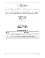
(GMA 1347D -00 Shown)
GMA 1347DInstallation Manual
Page 1: ...190 00303 21 January 2010 Revision C GMA 1347D 00 Shown GMA 1347D Installation Manual...
Page 2: ...manual or of any revision hereto provided that such electronic or printed copy of this manual or revision must contain the complete text of this copyright notice and provided further that any unautho...
Page 3: ...R TEL AUX to Equipment Description 1 2 1 2 2 Added to Interface Summary 1 7 1 6 Updated warranty statement 2 1 2 1 2 2 2 Updated AC reference C 2 2 2 3 2 3 1 Added marker beacon installation guidance...
Page 4: ...eased or disclosed to foreign nationals inside or outside of the United States without first obtaining an export license A violation of the EAR may be subject to a penalty of up to 10 years imprisonme...
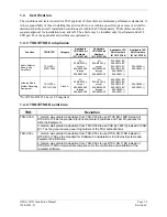
Page 5: ...2 4 2 5 Cooling Air 2 4 2 6 Mounting Requirements 2 5 2 7 Installation Approval Considerations for Pressurized Aircraft 2 6 2 8 Electrical Noise 2 6 3 INSTALLATION PROCEDURE 3 1 3 1 Unpacking Unit 3...
Page 6: ...GMA 1347D Outline Drawing A 1 A 2 GMA 1347D Connector Rack Assembly Drawing A 3 A 3 GMA 1347D Recommended Panel Cutout Dimensions A 5 B 1 GMA 1347D Power Antenna and Reversionary Mode Interconnect Wi...
Page 7: ...ker Pin Assignments J3472 4 8 4 9 Digital Audio Pin Assignments J3472 4 8 4 10 PA MUTE Pin Assignments J3472 4 8 4 11 Mic Audio Inputs and Mic Key Pin Assignments J3471 4 9 4 12 Remote ICS Audio and I...
Page 8: ...ate and the purpose of the modification The table is current at the time of publication of this manual see date on front cover and is subject to change without notice Authorized Garmin Sales and Servi...
Page 9: ...MA 1347D Audio Panel incorporates a microcontroller for processing front panel key commands annunciator control input output functions and communication The GMA 1347D includes a five position intercom...
Page 10: ...f fail safe connection for Pilot PTT mic and Pilot s Headset Left to ON SIDE COM Digital audio interface Voice Recorder Cockpit Call 20 only 1 2 2 Interface Summary The following is an interface summa...
Page 11: ...Garmin part number 005 00314 79 To obtain a copy of this form see the dealer OEM portion of the Garmin web site www garmin com 1 3 1 Physical Characteristics Characteristic Specification Bezel Height...
Page 12: ...MS for full output typical 1 Vac RMS MAX 3 Vp p Microphone signal processing 9 pole characteristic and special cabin noise band de emphasis Intercom isolation modes 00 2 Pilot Isolate Crew Isolate Int...
Page 13: ...3 39 006 C0051 20 006 C0075 00 006 C0075 01 006 C0075 03 006 C0090 006 C0091 006 C0090 006 C0091 Airborne Radio Marker Receiving Equipment TSO C35d ETSO 2C35d Class A All 006 B0203 except 006 B0203 00...
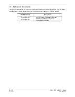
Page 14: ...ications are sources of additional information for installing the GMA 1347D Before installing the unit the technician should read all referenced materials along with this manual Part Number Document 1...
Page 15: ...MERCHANTABILITY OR FITNESS FOR A PARTICULAR PURPOSE STATUTORY OR OTHERWISE THIS WARRANTY GIVES YOU SPECIFIC LEGAL RIGHTS WHICH MAY VARY FROM STATE TO STATE IN NO EVENT SHALL GARMIN BE LIABLE FOR ANY...
Page 16: ...Page 1 8 GMA 1347D Installation Manual Revision C 190 00303 21 This page intentionally left blank...
Page 17: ...t Only 011 01257 00 010 00465 00 GMA 1347D Cabin Unit Only 011 01257 20 010 00465 20 2 2 1 Equipment Available Each of the following accessories are provided separately for the GMA 1347D Item Garmin P...
Page 18: ...way as possible from transmitter antennas 2 3 1 2 Marker Beacon Antenna Mounting Install the antenna according to the antenna manufacturer s instructions If the antenna is being installed on a composi...
Page 19: ...hield to D Sub as short as possible Ensure the distance from the beginning of the exposed shield to D Sub is no more than 1 5 inches long Terminate the center conductor by directly connecting it to th...
Page 20: ...rrels inside the backshell If using 16 or 18 barrel contacts ensure that no two contacts are mounted directly adjacent to each other This minimizes the risk of contacts touching and shorting to adjace...
Page 21: ...ields HIRF The GMA 1347D is mounted using its own system rack Figure 2 2 shows the GMA 1347D unit rack The unit rack is fastened to the aircraft instrument panel using the nutplate kit and bracket kit...
Page 22: ...ther take care to minimize effects from coupled interference and ground loops Coupled interference can sneak into audio system interconnecting cables when they are routed near large AC electric fields...
Page 23: ...cable requires a BNC plug connector on both ends Follow BNC connector manufacturer instructions for assembly of the BNC connector 3 4 Electrical Connections All electrical connections to the GMA 1347...
Page 24: ...change without notice 2 Extracting the 16 18 and 20 contact requires that the expanded wire barrel be cut off from the contact It may also be necessary to push the pin out from the face of the connec...
Page 25: ...noting proper orientation as shown on the installation drawing in Appendix A 6 Lock the GMA 1347D in place using the appropriate size hex wrench 3 7 Post Installation Configuration and Checkout NOTE...
Page 26: ...Page 3 4 GMA 1347D Installation Manual Revision C 190 00303 21 This page intentionally left blank...
Page 27: ...22 23 24 25 26 27 28 29 30 31 32 33 34 35 36 37 38 39 40 41 42 43 44 45 46 47 48 49 50 51 52 53 54 55 56 57 58 59 60 61 62 63 64 65 66 67 68 69 70 71 72 73 74 75 76 77 78 Figure 4 1 Rear Connectors J3...
Page 28: ...M AUDIO LO I O 14 CROSS SIDE NAV AUDIO IN HI In 15 DME AUDIO IN HI In 16 DME AUDIO IN LO In 17 MUSIC IN 1 LEFT In 18 MUSIC IN 1 RIGHT In 19 UNSWITCHED AUDIO IN 1 HI In 20 UNSWITCHED AUDIO IN 2 HI In 2...
Page 29: ...DIO IN HI In 55 ALTITUDE WARN AUDIO IN LO In 56 MUSIC IN 2 LEFT In 57 MUSIC IN 2 RIGHT In 58 COM 3 AUDIO IN HI In 59 COM 3 AUDIO LO I O 60 REMOTE CREW ICS OUT HI Out 61 REMOTE ICS OUT LO Out 62 TEL MI...
Page 30: ...ER GROUND 15 RESERVED 16 POWER GROUND 17 COM SWAP In 18 PROGRAM GROUND 19 SPARE 20 RESERVED 21 RESERVED 22 RESERVED 23 PROGRAM GROUND 24 RESERVED 00 RECORER OFF SELECT 20 In 25 PROGRAM GROUND 26 RESER...
Page 31: ...HTING HI In 53 AIRCRAFT POWER 1 In 54 SPARE 55 AIRCRAFT POWER 1 In 56 REVERSIONARY MODE 2 Out 57 REVERSIONARY MODE COMMON 2 Out 58 RESERVED 59 MARKER ANTENNA LO In 60 RESERVED 61 CROSS SIDE VOICE ALER...
Page 32: ...Unit power In 69 POWER GROUND Aircraft ground 71 POWER GROUND Aircraft ground 14 POWER GROUND Aircraft ground 16 POWER GROUND Aircraft ground 27 GMA REMOTE POWER OFF ARINC active high signal turns uni...
Page 33: ...able 4 6 Marker Beacon Pin Assignments J3472 Pin Pin Name Description I O 34 MIDDLE MARKER SENSE 2 5 8 Vdc into 4 7 k Out 74 AIRWAY INNER MARKER EXT LAMP OUT 00 MKR I HI white 2 5 8 Vdc into 56 Out 75...
Page 34: ...digital input for GMA 2 In 28 ON SIDE NAV DIGITAL AUDIO IN NAV 1 digital input for GMA 1 NAV 2 digital input for GMA 2 In 68 CROSS SIDE NAV DIGITAL AUDIO IN NAV 2 digital input for GMA 1 NAV 1 digital...
Page 35: ...udio and ground reference In 63 PASS 4 MIC AUDIO IN HI In 64 PASS 4 MIC AUDIO IN LO Passenger 4 Mic audio and ground reference In Denotes Active Low Inputs ground to activate Outputs grounded when act...
Page 36: ...or GMA 1 COM 1 audio output for GMA 2 Out 13 CROSS SIDE COM AUDIO LO Ground reference for COM 2 audio GMA 1 Ground reference for COM 1 audio GMA 2 58 COM 3 AUDIO IN HI COM 3 audio input In 77 COM 3 MI...
Page 37: ...put In 76 MUSIC IN 2 LO Ground reference for music 2 In 4 4 7 Unswitched Audio Inputs Table 4 17 Unswitched Audio Inputs Pin Assignments J3471 Pin Pin Name Description I O 19 UNSWITCHED AUDIO IN 1 HI...
Page 38: ...input In 36 ADF AUDIO IN LO Ground reference for automatic direction finder audio input In 4 4 10 Failsafe Audio Table 4 20 Failsafe Audio Pin Assignments J3471 Pin Pin Name Description I O FAIL SAFE...
Page 39: ...APPENDIX A ASSEMBLY AND INSTALLATION DRAWINGS GMA 1347D Installation Manual Page A 1 Page A 2 blank 190 00303 21 Revision C Figure A 1 GMA 1347D Outline Drawing...
Page 40: ...APPENDIX A ASSEMBLY AND INSTALLATION DRAWINGS GMA 1347D Installation Manual Page A 3 Page A 4 blank 190 00303 21 Revision C Figure A 2 GMA 1347D Connector Rack Assembly Drawing...
Page 41: ...04 2X 3 403 86 42 R 200 5 08 4X 0 0 00 703 17 84 670 17 02 2X 620 15 75 2X 265 6 73 620 15 75 648 16 45 2X 335 8 51 BEZEL CENTER CUTOUT CENTER NOTES 1 DIMENSIONS INCHES mm 2 IF THE FRONT LIP OF THE MO...
Page 42: ...APPENDIX B INTERCONNECT DRAWINGS GMA 1347D Installation Manual Page B 1 Page B 2 blank 190 00303 21 Revision C Figure B 1 GMA 1347D Power Antenna and Reversionary Mode Interconnect Wiring Diagram...
Page 43: ...APPENDIX B INTERCONNECT DRAWINGS GMA 1347D Installation Manual Page B 3 Page B 4 blank 190 00303 21 Revision C Figure B 2 GMA 1347D Power Antenna and Reversionary Mode Interconnect Wiring Diagram...
Page 44: ...APPENDIX B INTERCONNECT DRAWINGS GMA 1347D Installation Manual Page B 5 Page B 6 blank 190 00303 21 Revision C Figure B 3 Mic and Phone Jack Connections Interconnect Wiring Diagram...
Page 45: ...APPENDIX B INTERCONNECT DRAWINGS GMA 1347D Installation Manual Page B 7 Page B 8 blank 190 00303 21 Revision C Figure B 4 Transceiver Analog Connections Interconnect Wiring Diagram...
Page 46: ...APPENDIX B INTERCONNECT DRAWINGS GMA 1347D Installation Manual Page B 9 Page B 10 blank 190 00303 21 Revision C Figure B 5 Transceiver Digital Connections Interconnect Wiring Diagram...
Page 47: ...APPENDIX B INTERCONNECT DRAWINGS GMA 1347D Installation Manual Page B 11 Page B 12 blank 190 00303 21 Revision C Figure B 6 Discrete Lines Interconnect Wiring Diagram...