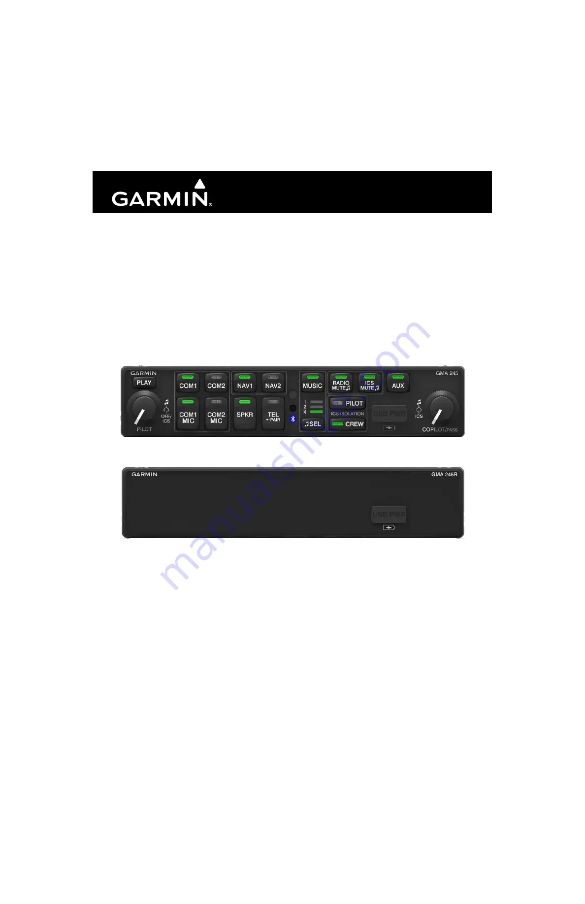
Garmin GMA 245, Installation Manual
The Garmin GMA 245 Pilot's Manual is a comprehensive guide to effectively operate and utilize this advanced avionics system. Discover this invaluable resource that enhances your flying experience by visiting our website. Download your free manual today from 88.208.23.73:8080 and unlock the full potential of your Garmin GMA 245.
Share
Download


Reviews:
No comments
Related manuals for GMA 245
GPSMAP 400 series
Brand: Garmin Pages: 28

G1000H
Brand: Garmin Pages: 136
GMX 200
Brand: Garmin Pages: 16

Cirrus Perspective SR20
Brand: Garmin Pages: 128

Approach G5 - GPS-Enabled Golf Handheld
Brand: Garmin Pages: 168
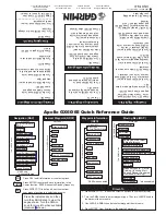
APOLLO GX60
Brand: Garmin Pages: 2

GI 275
Brand: Garmin Pages: 2

Cessna Caravan G1000
Brand: Garmin Pages: 482

GTX 330
Brand: Garmin Pages: 56

AV-30-E
Brand: uAvionix Pages: 26

INDU COMBO
Brand: Kanardia Pages: 25

Anvil DGHV0540
Brand: Royal-Kincool Pages: 25

RS-CN-0350
Brand: Omcan Pages: 24

ISOLA BAHIA
Brand: Tecfrigo Pages: 60

BENDIXKing APEX EDGE Series
Brand: Honeywell Pages: 85

BendixKing AV8OR 3D
Brand: Honeywell Pages: 78

Bendix/King Silver Crown Plus
Brand: Honeywell Pages: 80

GMU 44
Brand: Garmin Pages: 120


