Garmin GMU 44, Installation Manual
The Garmin GMU 44 is a state-of-the-art avionics product designed to enhance your aircraft's performance. This compact unit provides precise attitude and heading data, ensuring accurate navigation. For the convenience of our valued customers, we offer a detailed Installation Manual for free download at 88.208.23.73:8080, enabling seamless integration into your aircraft's system.
Share
Download

Reviews:
No comments
Related manuals for GMU 44
SkyView HDX System
Brand: Dynon Pages: 27

CHDD-2000 Series
Brand: Barco Pages: 4

ST 360 ALT
Brand: S-TEC Pages: 36

AKV 116
Brand: Ideal AKE Pages: 168
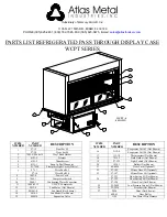
WCPT-3
Brand: Atlas Metal Pages: 3

4554647011
Brand: Nordcap Pages: 14

RC Allen Instruments RCA 2610-2
Brand: Kelly Manufacturing Pages: 18

VG930M - 19" LCD Monitor
Brand: ViewSonic Pages: 27
VA2249S
Brand: ViewSonic Pages: 25

F5MR48N
Brand: Delfield Pages: 2

iLevil 3 AW
Brand: Levil Aviation Pages: 11

iLevil 3 SW
Brand: Levil Aviation Pages: 11

iLevil 2 SW
Brand: Levil Technology Pages: 12

AF-5400
Brand: Advanced Flight Systems Pages: 126


