background image

Av. Kit Install. Manual

190-00067-62 Rev. E

Page 1

GNC 250/GNC 250XL/GPS 150XL

INSTALLATION MANUAL

GARMIN INTERNATIONAL, INC.

PART NUMBER: 190-00067-62

1200 E. 151st STREET

REVISION E, 3 APRIL 1998

OLATHE, KANSAS 66062-3426

Summary of Contents for GNC 250

Page 1: ... Install Manual 190 00067 62 Rev E Page 1 GNC 250 GNC 250XL GPS 150XL INSTALLATION MANUAL GARMIN INTERNATIONAL INC PART NUMBER 190 00067 62 1200 E 151st STREET REVISION E 3 APRIL 1998 OLATHE KANSAS 66062 3426 ...

Page 2: ...lectronic without the expressed written consent of Garmin International Garmin International Inc 1200 E 151st Street Olathe KS 66062 U S A REVISION RECORD ECO Rev Date of Rev Description FAA Approval Initial Rev A 16 Dec 1996 Initial release 6811 Rev B 07 Mar 1997 Enhance Cooling Air Section 7708 Rev C 10 Dec 1997 Add ant note STC Chg btry GPN 8322 Rev D 28 Jan 1998 Chg to from voltage install dwg...

Page 3: ... VHF COMM INTERFERENCE OF GPS 2 1 6 COMM ANTENNA INSTALLATION CONSIDERATIONS 2 2 RACK CONSIDERATIONS 2 2 1 ACCESSIBILITY 2 3 CABLING AND WIRING 2 4 COOLING AIR 2 5 ANNUNCIATORS 2 6 EXTERNAL ALTITUDE INPUT SECTION 3 INSTALLATION PROCEDURE 3 1 INSTALLATION ACCESSORIES 3 2 ANTENNA INSTALLATION 3 3 CABLE INSTALLATION 3 4 RACK INSTALLATION 3 5 UNIT INSTALLATION AND REMOVAL 3 6 COMM ANTENNA INSTALLATION...

Page 4: ...6 PIN HD DSUB GNC 250 GNC 250XL only 1 3 INTERCONNECT SCHEMATIC 1 4 INTERCONNECT SCHEMATIC NOTES 2 1 GPS ANTENNA INSTALLATION CONSIDERATIONS 2 2 UNIT INSTALLATION CONSIDERATIONS 3 1 STUD MOUNT GA 56 INSTALLATION 3 2 FLANGE MOUNT GA 56 INSTALLATION 3 3 COAX CABLE INSTALLATION 3 4 AVIATION RACK DIMENSIONS 3 5 AVIATION RACK INSTALLATION ...

Page 5: ...the responsibility of those desiring to install this article on or within a specific type or class of aircraft to determine that the aircraft operating conditions are within the TSO standards The article may be installed only if further evaluation by the user installer documents an acceptable installation and is approved by the Administrator 1 2 1 PHYSICAL CHARACTERISTICS Width 6 25 inches Height ...

Page 6: ...rallel Pins 3 and 4 loads 375 millivolts for flag out of view and 40 millivolts for flag in view OBI data Output providing bearing to waypoint data for a Pins 7 8 and 23 Bendix King RMI KI 229 or equivalent Message annunciator Output capable of driving negative logic message Pin 20 annunciators by sinking up to 500mA RS232 chan 1 output data Output capable of driving devices as listed in Section 4...

Page 7: ...ded swaps the active and Pin 10 standby COMM frequencies TX Interlock Input when grounded reduces receiver sensitivity so Pin 12 squelch will not break when another transceiver is keyed Altimeter input Capable of receiving encoded output data from any Pins 14 24 parallel altimeter device Remote Enter Input when ground functions the same as the enter Pin 26 key on the UNIT front panel 1 2 3 3 COMM ...

Page 8: ... the more stringent requirements For Home or Office Use The following guidance is provided to help ensure the proper licensing of the GNC 250 and GNC 250XL COMM 1 Telecommunications Act of 1996 effective February 8 1996 provides the FCC discretion to eliminate radio station license requirements for aircraft At present and individual license to operate the GNC 250XL and GNC 250 aboard a private air...

Page 9: ...f 3 feet from the UNITS and its GPS antenna The UNITS COMM antenna connector is specified to have installed GPN 330 00067 00 1 57542 GHz notch filter to minimize interfering harmonics 2 1 3 ELECTRICAL BONDING No special precautions need to be taken to provide a bonding path between the GPS antenna and the aircraft structure Follow the manufacturers instructions for the COMM antenna GNC 250 GNC 250...

Page 10: ...s recommendations 2 2 RACK CONSIDERATIONS 2 2 1 ACCESSIBILITY Plan a location which gives the pilot complete and comfortable access to the entire keypad and which is plainly visible from the pilot s perspective Check that there is adequate depth for the rack in the instrument panel A location away from heating vents or other sources of heat generation is optimal Figure 2 2 illustrates a typical av...

Page 11: ...ystem performance during times of minimal satellite coverage or poor satellite geometry Pressure altitude input from an external source may be derived from a RS 232 compatible serial altitude input or Parallel Greycode Gillham Altitude GNC 250 GNC 250XL only as described in Section 4 of this manual Gillham Altitude is not required when serial altitude is used SECTION 3 INSTALLATION PROCEDURE 3 1 I...

Page 12: ...2 00 THE FOLLOWING INSTALLATION ACCESSORIES ARE REQUIRED BUT NOT PROVIDED GNC 250 GNC 250XL ONLY COMM ANTENNA BROAD BAND 50 OHM VERTICALLY POLARIZED WITH COAXIAL CABLE HEADPHONES 500 OHM NOMINAL IMPEDANCE MICROPHONE LOW IMPEDANCE CARBON OR DYNAMIC WITH TRANSISTORIZED PRE AMP 3 2 ANTENNA INSTALLATION For the COMM antenna follow the manufacturers instructions GNC 250 GNC 250XL only The remainder of ...

Page 13: ...5 722 See Appendix B for information regarding obsolete stamped type contacts Tools Hand Standard Density Connectors size 20 contacts Hi Dens Connector size 22D Crimping pin or socket contacts 20 24 AWG pin or socket contacts 18 AWG pin contacts 22 28 AWG Tool positioner insert extract positioner insert extract positioner insert extract military p n M22520 2 01 M22520 2 08 M81969 1 02 n a M81969 1...

Page 14: ...e and rotate counter clockwise until the mounting screw turns freely and the unit protrudes about 3 8 inch from the panel Be sure not to over tighten the unit into the rack The application of hex drive tool torque exceeding 15 in lbs can damage the locking mechanism 3 6 COMM ANTENNA INSTALLATION CHECK GNC 250 GNC 250XL only Check for insertion loss and VSWR VSWR should be checked with an in line t...

Page 15: ...knobs see the appropriate chapter of the Pilot s Guide for more information on page and data selection Note that some pages found in test mode are intended for bench testing and are not discussed here 4 2 INSTALLATION CONFIGURATION Note that the below pages are in the order found when rotating the outer knob clock wise starting at the Display Test page See Section 4 1 to get to this page 4 2 1 DIS...

Page 16: ...ent System TSO d Shadin 91053XT Series Digital Fuel Management System TSO d arnav ei fuel Fuel information received from Arnav Model FC 10 Fuel Computer TSO d Arnav Model FT 10 Fuel Totalizer TSO d Electronics International Model FP 5L Fuel Flow Computer Non TSO d shadin adc Air data information received from Various models from the 9628XX X family shadin fadc Fuel Air data information received fr...

Page 17: ...t Below is a list of labels output by the UNIT Navigation position data Label octal Description 100 Selected course 114 Desired track 115 Bearing to waypoint 116 Cross track error 121 Horizontal command to autopilot 251 Distance to go 252 Time to go 310 Present position latitude 311 Present position longitude 312 Ground speed 313 Ground track 147 Magnetic variation 261 GPS navigation mode 275 Navi...

Page 18: ...4 2 5 CONFIGURATION Select the Configuration Test Page Change the selectable Strap and Fuel selections to match that of the aircraft The available options are Fuel av gas Using Aviation gas 5 8 lbs gal jet A Using Jet A Jet A 1 fuel 6 7 lbs gal jet B Using Jet B JP 4 fuel 6 5 lbs gal NOTE The Fuel option is used to designate the type of fuel used so that the correct fuel density will be used in ca...

Page 19: ...racters that the GNC 250 transmits RMC 70 characters GGA 72 characters GSA 57 characters GSV 140 characters 70 characters x 2 sentences RMB 70 characters BOD 35 characters W P L 38 characters PGRME 35 characters GARMIN proprietary accuracy error sentence that is not a part of the NMEA 0183 standard 4 3 GROUND TEST The UNIT ground test procedure incorporates a series of display pages to test CDI fl...

Page 20: ...charger if the External Power is the current source and its voltage is high enough When in Auto mode auto status will be either on or off reflecting whether the charger is enabled or disabled The next line reports the status of the internal memory battery as shown below Mem Batt ok low Note that the TX field will light on the display but the transmitter will not actually transmit when the UNIT is ...

Page 21: ...TT field changes from off to on Press Remote Transfer and verify the Rmt xfr field changes from off to on 4 3 5 COMMUNICATIONS LOOPBACK TEST This page displays the results of communication loop back tests Three channels are tested RS232 channels 1 and 2 and Arinc 429 Results of the test are either OPEN or OK Open means the channel s transmitter and receiver are not connected or the test failed The...

Page 22: ...age will be displayed followed by the Data Base Page Upon approval of the Data Base Page the Satellite Status Page will be displayed If unable to acquire satellites relocate the aircraft away from obstructions which might be shading reception If the situation does not improve check the antenna installation Once GPS position information is available use the DIRECT TO key to activate the navigation ...

Page 23: ...al electrical noise which would reduce the COMM receiver sensitivity by increasing the squelch threshold If possible verify the communications capability on both the high and low end of the VHF COMM band SECTION 5 CERTIFICATION The GNC 250 GNC 250XL GPS150XL is certified to the airworthiness criteria in Advisory Circular 20 138 for VFR use in the en route and terminal phases of flight The GNC 250 ...

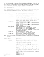
Page 24: ...Av Kit Install Manual 190 00067 62 Rev E Page 24 FIGURE 1 1 PINOUT DEFINITION 37 PIN DSUB ...

Page 25: ...Av Kit Install Manual 190 00067 62 Rev E Page 25 FIGURE 1 2 PINOUT DEFINITION 26 PIN HD DSUB GNC 250 GNC 250XL ONLY ...

Page 26: ...Av Kit Install Manual 190 00067 62 Rev E Page 26 FIGURE 1 3A INTERCONNECT SCHEMATIC ...

Page 27: ...Av Kit Install Manual 190 00067 62 Rev E Page 27 FIGURE 1 3B INTERCONNECT SCHEMATIC ...

Page 28: ...Av Kit Install Manual 190 00067 62 Rev E Page 28 FIGURE 1 4 INTERCONNECT SCHEMATIC NOTES ...

Page 29: ...m compass safe distance FIG 2 2 UNIT INSTALLATION CONSIDERATIONS FIG 2 1 GPS ANTENNA INSTALLATION CONSIDERATIONS Antenna masked by vertical fin T tail or dorsal fin Antenna must be on top of aircraft OK RTE SQ NRST D ACTV STBY NAV WPT MSG GARMIN GNC 250 CRSR CLR ENT ...

Page 30: ...Av Kit Install Manual 190 00067 62 Rev E Page 30 FIG 3 1 STUD MOUNT GA 56 ANTENNA INSTALLATION ...

Page 31: ...Av Kit Install Manual 190 00067 62 Rev E Page 31 FIGURE 3 2 FLANGE MOUNT GA 56 ANTENNA INSTALLATION ...

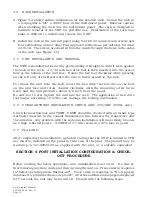
Page 32: ...Av Kit Install Manual 190 00067 62 Rev E Page 32 FIGURE 3 3 COAX CABLE INSTALLATION ...

Page 33: ...stall Manual 190 00067 62 Rev E Page 33 FIGURE 3 4 AVIATION RACK DIMENSIONS COG X COG Y COG Z Unit Weight w o Rack GNC 250 3 56 1 00 2 64 2 4 LBS GNC 250XL 3 40 0 93 2 34 2 6 LBS GPS 150XL 3 45 0 85 2 19 1 7 LBS ...

Page 34: ...Av Kit Install Manual 190 00067 62 Rev E Page 34 FIGURE 3 5 AVIATION RACK INSTALLATION ...

Page 35: ... QRWHG RZ 7HPSHUDWXUH LJK 7HPSHUDWXUH Q OLJKW RVV RI RROLQJ RROLQJ DLU QRW UHTXLUHG OWLWXGH HFRPSUHVVLRQ 2YHUSUHVVXUH 1RW WHVWHG 7HPSHUDWXUH 9DULDWLRQ TXLSPHQW WHVWHG WR DWHJRU XPLGLW TXLSPHQW WHVWHG WR DWHJRU 6KRFN TXLSPHQW WHVWHG SHU 2 3DU 2SHUDWLRQDO UDVK 6DIHW 9LEUDWLRQ TXLSPHQW WHVWHG ZLWKRXW VKRFN PRXQWV WR DWHJRULHV 0 DQG 1 7DEOH SORVLRQ TXLSPHQW LGHQWLILHG DV DWHJRU QR WHVW UHTXLUHG DWHUSU...

Page 36: ...G WR DWHJRU 9ROWDJH 6SLNH TXLSPHQW WHVWHG WR DWHJRU XGLR UHTXHQF 6XVFHSWLELOLW TXLSPHQW WHVWHG WR DWHJRU QGXFHG 6LJQDO 6XVFHSWLELOLW TXLSPHQW WHVWHG WR DWHJRU 5DGLR UHTXHQF 6XVFHSWLELOLW TXLSPHQW WHVWHG WR DWHJRU 7 5DGLR UHTXHQF PLVVLRQ TXLSPHQW WHVWHG WR DWHJRU LJKWQLQJ QGXFH 7UDQVLHQW 6XVFHSWLELOLW TXLSPHQW LGHQWLILHG DV DWHJRU QR WHVW UHTXLUHG LJKWQLQJ LUHFW IIHFWV TXLSPHQW LGHQWLILHG DV DWHJRU...

Page 37: ... LJK 7HPSHUDWXUH Q OLJKW RVV RI RROLQJ RROLQJ DLU QRW UHTXLUHG OWLWXGH HFRPSUHVVLRQ 1RW WHVWHG 2YHUSUHVVXUH 1RW WHVWHG 7HPSHUDWXUH 9DULDWLRQ TXLSPHQW WHVWHG WR DWHJRU XPLGLW TXLSPHQW WHVWHG WR DWHJRU 6KRFN TXLSPHQW WHVWHG SHU 2 3DU 2SHUDWLRQDO UDVK 6DIHW 1RW DSSOLFDEOH 9LEUDWLRQ TXLSPHQW WHVWHG ZLWKRXW VKRFN PRXQWV WR DWHJRULHV 0 DQG 7DEOH SORVLRQ TXLSPHQW LGHQWLILHG DV DWHJRU QR WHVW UHTXLUHG DWH...

Page 38: ...SPHQW LGHQWLILHG DV DWHJRU QR WHVW UHTXLUHG 3RZHU QSXW TXLSPHQW LGHQWLILHG DV DWHJRU QR WHVW UHTXLUHG 9ROWDJH 6SLNH TXLSPHQW LGHQWLILHG DV DWHJRU QR WHVW UHTXLUHG XGLR UHTXHQF 6XVFHSWLELOLW TXLSPHQW LGHQWLILHG DV DWHJRU QR WHVW UHTXLUHG QGXFHG 6LJQDO 6XVFHSWLELOLW TXLSPHQW LGHQWLILHG DV DWHJRU 5DGLR UHTXHQF 6XVFHSWLELOLW TXLSPHQW LGHQWLILHG DV DWHJRU 7 5DGLR UHTXHQF PLVVLRQ TXLSPHQW LGHQWLILHG DV ...

Page 39: ...sed will vary with the installation When working with the stamped crimp type contacts the following tools should be used Tools 37 and 9 position connectors 26 position connector supplier Crimp Tool Extraction Tool Crimp Tool Extraction Tool Amp 58448 2 91067 22 90430 1 91285 1 ITT Cannon 995 2000 000 980 0008 124 995 2000 022 980 00004 804 Cinch HTD 544 CIET 20 HDB HTD 544 HTD 520 Part numbers sho...

Page 40: ...cts on the battery and the pin number assignments are different however the individual contact locations are unchanged The following table shows the pin assignments for the two different types of connectors Serial Number below 33050055 33050055 and up remote batt Pins sockets mating plug sockets pins function contact number contact number battery 1 5 battery 2 4 charge enable 3 3 aircraft power 4 ...

Page 41: ...craft GNC 250XL Consistent with N8110 69 or Order 8110 4 Aviation Authority approved installers are hereby granted permission to use STC SA00502WI data to modify aircraft GNC 150XL Consistent with N8110 69 or Order 8110 4 Aviation Authority approved installers are hereby granted permission to use STC SA00503WI data to modify aircraft Av Kit Install Manual 190 00067 62 Rev E Page 41 ...

Page 42: ...Av Kit Install Manual 190 00067 62 Rev E Page 42 ...

Page 43: ...Av Kit Install Manual 190 00067 62 Rev E Page 43 ...

Page 44: ...Av Kit Install Manual 190 00067 62 Rev E Page 44 ...

Reviews: