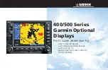
background image

400/500 Series 

Garmin Optional 

Displays

Pilot’s Guide Addendum For:

•GDL 49 Weather Datalink
•GDL 69/69A XM Satellite Datalink
•GTX 330/330D TIS
•Garmin TAWS (GPS 500 & GNS 530)
•Garmin TERRAIN

Summary of Contents for GPSMAP 400 series

Page 1: ...400 500 Series Garmin Optional Displays Pilot s Guide Addendum For GDL 49 Weather Datalink GDL 69 69A XM Satellite Datalink GTX 330 330D TIS Garmin TAWS GPS 500 GNS 530 Garmin TERRAIN...

Page 2: ...1 Garmin Corporation No 68 Jangshu 2nd Road Shijr Taipei County Taiwan Tel 886 2 2642 9199 Fax 886 2 2642 9099 Except as expressly provided herein no part of this addendum may be reproduced copied tra...

Page 3: ...by the Garmin 400 500 Series units is geometric height above mean sea level and could vary signi cantly from altitude displayed by pressure altimeters in aircraft Never use GPS altitude for vertical n...

Page 4: ...y Status and Pilot Response 5 Traf c Ground Track 6 Traf c Warning Window 6 Traf c Page 6 Traf c Page Display Range 6 Map Page 7 Con guring TIS Traf c Data on the Map Page 7 Highlighting TIS Traf c Us...

Page 5: ...Series Only 18 Request Shortcuts 18 Data Link Request Log Page GDL 49 Only 19 Sending Position Reports GDL 49 Only 19 Section 4 METAR Operation 20 Requesting Graphical METARS 20 Displaying Graphical M...

Page 6: ...FACE Section 1 Introduction 29 Overview 29 Operating Criteria 29 GPS Position and GPS MSL Altitude 29 TERRAIN Alerting using the GPS Position GPS MSL Altitude 30 Baro Corrected Altitude verses GPS MSL...

Page 7: ...lerting PDA 40 TERRAIN Failure Alert 41 TERRAIN Not Available Alert 41 TERRAIN Alert Summary 42 PART FOUR TAWS INTERFACE Section 1 Introduction 43 Overview 43 Operating Criteria 43 GPS Position and GP...

Page 8: ...ort Criteria TAWS Phase of Flight 53 TAWS Destination Airport 53 Section 3 TAWS Alerts 54 Forward Looking TERRAIN Avoidance 55 Premature Descent Alerting PDA 56 Excessive Descent Rate Alert EDR 57 Neg...

Page 9: ...is available to aircraft equipped with a Mode S Data Link such as the Garmin GTX 330 Transponder TIS Traf c from a GTX 330 Transponder can then be displayed on a Garmin 400 500 Series unit Surveillan...

Page 10: ...be no better than that provided to ATC TIS will only display aircraft with operating transponders installed TIS relies on surveillance of the Mode S radar which is a secondary surveillance radar simi...

Page 11: ...ircraft stabilizes When a rapidly closing intruder is on a course that crosses the client aircraft course at a shallow angle either overtaking or head on and either aircraft abruptly changes course wi...

Page 12: ...ximate aircraft For example when the rst Traf c Advisories appears on the TIS display the user is alerted audibly So long as a single aircraft remains on the TIS display no further audio alert is gene...

Page 13: ...has been removed from the display due to the age of the data being too old to coast for the time period of 12 60 seconds from the last receipt of a TIS message The pilot should be aware that traf c m...

Page 14: ...age TIS Traf c data is displayed on two 400 500 Series unit pages the Traf c Page and the Map Page The 500 Series unit can also be con gured to display a traf c thumbnail window below the VLOC frequen...

Page 15: ...on the Map Page TA PA Only traf c advisories and proximity advisories are displayed on the Map Page TA only Only traf c advisories are displayed on the Map Page From the Map Page you can display traf...

Page 16: ...plus the bearing and distance to the pointer from your present position To activate the panning feature and pan the map display 1 Press the small right knob to activate the panning target pointer 2 Tu...

Page 17: ...power up test the Standby Screen appears on the Traf c Page If the system passes the power up test and the aircraft is airborne as determined by system con guration at the time of installation see yo...

Page 18: ...orner of the display and begins to display traf c on the Traf c or Map Page The TIS Traf c Advisory TA should alert the crew to use additional vigilance to identify the intruding aircraft Any time the...

Page 19: ...roducts are available for display on the 400 500 Series unit via the Weather Data Link interface NEXRAD Data Graphical METAR Data Text based METAR Data Graphical Temperature Dewpoint Data Graphical Wi...

Page 20: ...adar scans Interference from buildings or mountains which may cause shadows NEXRAD Limitations Certain limitations exist regarding the NEXRAD radar displays Some but not all are listed for the user s...

Page 21: ...L 49 GDL 69 Atmos Cloud Rain Snow Sleet Hail 10 00 00 10 00 00 5 00 trace 0 00 trace 05 Very Light 5 00 trace 10 Light 10 0 trace 10 Light Light 15 01 1 2 Light Light 20 02 2 3 Light Light 25 05 3 5 L...

Page 22: ...titude and longitude This is only select able when requesting from the map The Position eld displays the position of the map cursor and cannot be edited From Flight Plan Request NEXRAD data from one o...

Page 23: ...o time period 3 To exit from the NEXRAD Request Page press CRSR The Data Link Page is displayed To request NEXRAD data from the Map Page 1 Select the Map Page 2 Press MENU The Map Page Options Menu is...

Page 24: ...urth page if a traf c sensor is also con gured Customizing NEXRAD Data on the Weather Page You can customize the NEXRAD data on the Weather Page from the Page Options Menu To customize the NEXRAD data...

Page 25: ...sired range selec tion Press CLR to go back to the Map Page 5 Highlight the NEXRAD DENSITY eld use the small right knob to set the density desired i e the transparency of the NEXRAD cells The density...

Page 26: ...Airport Location Page To select the Airport Location Page use one of the following three methods 1 Use the inner right knob and select the Airport Location Page from the WPT Group of pages 2 On the M...

Page 27: ...om the nearest VOR Radial The radial from the nearest VOR Position Displays your current position expressed in Latitude and Longitude Auto Request This eld is used to set the time interval for the sys...

Page 28: ...ptions Menu is displayed 3 Select Request METAR and press ENT The METAR Request Page is displayed containing the following elds Format This eld allows the user to select between the type of METAR Data...

Page 29: ...Graphical METAR Data for a Speci c Airport from the Map Page As a shortcut Graphical METAR Data can be viewed for a speci c airport from the Map Page 1 Select the Map Page 2 Move the Map Cursor and h...

Page 30: ...nob and select METAR WINDS or TEMP DP 3 Press MENU The Weather Page Menu is displayed 4 Turn the small right knob highlight Display Legend and press ENT The Weather Legend Page is displayed for the ty...

Page 31: ...NT 2 Turn the small right knob and scroll through the list of four letter identi ers 3 Highlight the desired identi er and press ENT 4 The text box displays the METAR data for the selected identi er 5...

Page 32: ...urn the small right knob and select TEMP DP 4 Press CRSR The Temperature Dewpoints are displayed on the NAV Weather Page Displaying Wind Data To display wind data on the NAV Weather Page 1 Select the...

Page 33: ...ta Link Status Page may provide insight to a possible failure Information dis played at this page should be noted and provided to the repair station The Connectivity Message table should also provide...

Page 34: ...e satellite _ _ _ RS 232 communication with the GDL 49 has been lost SATCOM Operation This eld indicates the current activity being performed by the satel lite communicator within the GDL 49 The follo...

Page 35: ...0 none 1 poor 2 good and 3 excellent 0 1 2 or 3 Satellite radio service is not activated Satellite signal quality is indicated by the numbers 0 1 2 or 3 where 0 none 1 poor 2 good and 3 excellent Conn...

Page 36: ...28 Section 6 Troubleshooting This page intentionally left blank...

Page 37: ...s the following to operate properly The system must have a valid 3D GPS position solution The system must have a valid terrain obstacle database GPS Position and GPS MSL Altitude Garmin TERRAIN uses i...

Page 38: ...ected Altitude can be achieved by frequently updating the altimeter setting to the nearest reporting station along the ight path However because actual atmosphere conditions seldom match the standard...

Page 39: ...standard temperature environments may require the pilot to compensate for the non standard temperature by increasing the minimum altitude that is de ned in the approach procedure for standard atmosph...

Page 40: ...Figure 2 2 The page displays terrain information aircraft ground track and GPS derived MSL altitude Altitude is shown in increments of 20 feet or in increments of 10 meters depending on unit con gurat...

Page 41: ...tion information on or off Inhibit Mode The Garmin TERRAIN system provides an inhibit mode This mode is designed to deactivate PDA FLTA visual alerts when they are deemed unnecessary by the pilot Flyi...

Page 42: ...to represent obstacles and potential impact points on the Terrain Page Note that obstacle symbols are shown on display zoom ranges up to 10 nm Unlighted Obstacles 1000 AGL Lighted Obstacles 1000 AGL U...

Page 43: ...shown on the Terrain Data base Versions Page located in the AUX Page Group Figure 2 7 Databases are checked for integrity at power up If a database is found to be missing and or de cient the TERRAIN...

Page 44: ...se As explained in the Premature Descent Alerting PDA section page 40 the Garmin TERRAIN pre mature descent alerting PDA algorithms utilize data contained in the Navigation Database It is therefore im...

Page 45: ...t to include only airports with runways 5000 or longer only these are added to the nearest airport list The terrain phase of ight is affected in that all airport runways under 5000 are NOT included in...

Page 46: ...is issued visual annunciations are displayed Annunciations appear in a dedicated eld in the lower left corner of the display Figure 3 1 Pop up Alerts On any page except the TERRAIN Page when a terrai...

Page 47: ...rt is given when the projected vertical ight path is calculated to come within minimum clearance altitudes in the following table Phase of Flight Level Flight Descending Enroute 700 ft 500 ft Terminal...

Page 48: ...altitude of 125 AGL while within 1 nm of the threshold ILS Approach Loaded PDA alerting begins when the aircraft is within 15 nm of the destination airport and the aircraft is on the ight plan path P...

Page 49: ...Figure 3 5 TERRAIN Not Available Alert The TERRAIN system requires a 3D GPS navigation solution along with speci c vertical accuracy minimums Should the navigation solution become degraded if the terr...

Page 50: ...otAvailable None RequiredTerrain Clearance RTC Advisory RequiredTerrain Clearance RTC Alert FLASHING FLASHING ImminentTerrain Impact ITI Advisory RequiredTerrain Impact ITI Alert FLASHING FLASHING Req...

Page 51: ...es the following to operate properly The system must have a valid 3D GPS position solution The system must have a valid terrain obstacle database GPS Position and GPS MSL Altitude Garmin TAWS uses inf...

Page 52: ...tmospheric conditions The most accurate Baro Corrected Altitude can be achieved by frequently updating the altimeter setting to the nearest reporting station along the ight path However because actual...

Page 53: ...altitude as indicated on the altimeter Operations in below standard temperature environments may require the pilot to compensate for the non standard temperature by increasing the minimum altitude tha...

Page 54: ...n regarding page groups and pages To display the TAWS Page select the NAV group and turn the small right knob until the TAWS Page is displayed Terrain information aircraft ground track and GPS derived...

Page 55: ...allowing for a more complete view of the surrounding area To change the display range 1 Select the TAWS Page and press up or down on the RNG key to select the desired range 1 nm 2 nm 5 nm 10 nm 25 nm...

Page 56: ...always remember to enable the system when appropriate Only the PDA and FLTA alerts are disabled in the inhibit mode See section 3 for more information on TAWS alerts To inhibit TAWS 1 Select the TAWS...

Page 57: ...WS system 1 Select the TAWS Page and press MENU 2 Select the Test Terrain option Figure 2 5 3 Press ENT to con rm the selection An aural message is played giving the test results TAWS System Test OK i...

Page 58: ...olor TERRAIN Obstacle Loca tion Alert Level Suggested Aircrew Response Red TERRAIN Obstacle is within 100 or above aircraft altitude WARNING Initiate climb and or turn away from terrain obstacle Yello...

Page 59: ...own on the Terrain Database Versions Page located in the AUX Page Group Figure 2 8 Databases are checked for integrity at power up If a database is found to be missing and or de cient the TAWS system...

Page 60: ...As explained in the Premature Descent Alerting PDA section page 56 Garmin TAWS Premature Descent Alerting PDA algorithms utilize data contained in the navigation database It is therefore impor tant t...

Page 61: ...ot have PDA alerts issued As an example if the pilot con gures the unit to include only airports with runways 5000 or longer only these are added to the nearest airport list The TAWS phase of ight is...

Page 62: ...1 Annunciations are color coded according to Table 3 2 page 60 Pop up terrain alerts can also appear during an alert but only when the TAWS Page is not displayed There are two options when an alert is...

Page 63: ...ft 500 ft Terminal 350 ft 300 ft Approach 150 ft 100 ft Departure 100 ft 100 ft Table 3 1 Minimum TERRAIN Clearance Values for RTC ITI Alerts During the nal approach phase of ight RTC ITI alerts are a...

Page 64: ...hreshold ILS Approach Loaded PDA alerting begins when the aircraft is within 15 nm of the destination air port and the aircraft is on the ight plan path Prior to crossing the FAF the pilot will receiv...

Page 65: ...r the alert as de ned by TSO C151b Excessive Descent Rate Severity Levels WARNING The annunciation and pop up terrain alert are accompanied by the aural message Pull Up CAUTION The annunciation and po...

Page 66: ...n after takeoff The aural message Don t Sink is given for NCR alerts accompanied by an annunciation and a pop up terrain alert on the display NCR alerting is only active when departing from an airport...

Page 67: ...al items such as database validity hardware status and GPS status Should the system detect a failure the TAWS Page displays TERRAIN FAILED in yellow Figure 3 7 The aural message TAWS System Failure is...

Page 68: ...isplayed as constant white text on a red background Alert Type TAWS Page Annuciation Pop Up Alert Aural Message TAWS System Failure None TAWS System Failure Terrain Inhibited None None Terrain NotAvai...

Page 69: ...p or ObstacleAhead Pull Up ObstacleAhead Pull Up ImminentTerrain Impact ITI Caution or TerrainAhead TerrainAhead or Caution Terrain Caution Terrain Imminent Obstacle Impact IOI Warning or ObstacleAhea...

Page 70: ...62 Section 3 TAWS Alerts This page intentionally left blank...

Page 71: ...FT After FG Thick fog G Gusts TS Thunderstorm OBSCD Obscured BKN Broken clouds SM Statue Miles DZ Drizzle Trrn Terrain OVC Overcast clouds KT Knots RA Rain FM From VV Vertical Visibility SLP Sea Level...

Page 72: ...hics METAR Winds and Temperature Dewpoints Age Graphics 0 10 minutes Green 11 20 minutes Green 21 30 minutes Green 31 60 minutes Green 61 minutes Yellow Unknown Yellow METARs Precipitation Graphics Li...

Page 73: ...speed G10 Green Wind is gusting 5 10 kts more than sustained speed G11 Yellow Wind is gusting 11 kts or more above its sustained speed Gust Offset Wind Speed Wind Vector The symbol above indicates the...

Page 74: ...l displays the difference between the reported temperature and dew point Differences are shown in degrees Fahrenheit Temperature Dew Point Temp Dew Point Display Ranges Blank Unknown 11 Green 7 10 Gre...

Page 75: ......

Page 76: ...Inc 1200 East 151st Street Olathe Kansas 66062 U S A Garmin Europe Ltd Unit 5 The Quadrangle Abbey Park Industrial Estate Romsey SO51 9AQ U K Garmin Corporation No 68 Jangshu 2nd Road Shijr Taipei Co...

Reviews: