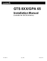
background image

190-00587-00 

April, 2009 

Revision 4TP 


GTS 8XX/GPA 65

Installation Manual 

(Includes the GA 58 Antenna) 


Summary of Contents for GPSMAP 800 Series

Page 1: ...190 00587 00 April 2009 Revision 4TP GTS 8XX GPA 65 Installation Manual Includes the GA 58 Antenna ...

Page 2: ...omplete text of this copyright notice and provided further that any unauthorized commercial distribution of this manual or any revision hereto is strictly prohibited Garmin International Inc 1200 E 151st Street Olathe KS 66062 USA Telephone 913 397 8200 Aviation Dealer Technical Support Line Toll Free 888 606 5482 www garmin com Garmin Europe Ltd Liberty House Bulls Copse Road Hounsdown Business P...

Page 3: ...sed or disclosed to foreign nationals inside or outside the United States without first obtaining an export license The preceding statement is required to be included on any and all reproductions in whole or in part of this manual NOTE Throughout this document references made to the GTS 8XX shall equally apply to the GTS 800 820 and 850 except where specifically noted WARNING This product its pack...

Page 4: ...Page ii GTS 8XX GPA 65 Installation Manual Revision 4TP 190 00587 00 This page intentionally left blank ...

Page 5: ...ments 2 15 2 6 Mounting Requirements 2 16 3 INSTALLATION PROCEDURE 3 1 3 1 Unpacking Unit 3 1 3 2 Wiring Harness Installation 3 1 3 3 QMA Connector Insertion and Removal 3 3 3 4 Backshell Pigtail Circular Connector and Configuration Module Assemblies 3 5 3 5 Unit Installation 3 5 3 6 GA 58 Antenna Installation 3 19 3 7 GPA 65 PA LNA Installation 3 20 3 8 Continued Airworthiness 3 20 4 SYSTEM INTER...

Page 6: ... 115 00784 00 2 16 3 1 Engaging QMA Connectors 3 3 3 2 Disengaging QMA Connectors 3 4 3 3 GTS 8XX Install Tool Normal Tab 3 7 3 4 GTS 8XX Install Tool Configuration Tab GTS 800 3 8 3 5 GTS 8XX Install Tool Configuration Tab GTS 820 and GTS 850 3 9 3 6 GTS 8XX Install Tool Upload Tab 3 12 3 7 Self Test 3 15 3 8 Ground Test 3 16 A 1 GTS 8XX Vertical Outline Drawing A 1 A 2 GTS 8XX Vertical Installat...

Page 7: ...2 3 Recommended Coaxial Length 2 12 2 4 Coaxial Cable Set Length Tolerance 2 13 3 1 Socket and Pin Contact part Numbers 3 1 3 2 Socket Contact MIL SPEC M39029 5 115 Crimp Tooling 3 1 3 3 Pin Contact GPN 336 00021 00 MIL SPEC M39029 58 360 Crimp Tooling 3 2 3 4 Pin Socket Contacts GPN 336 00022 00 MIL SPEC M39029 63 368 and GPN 336 00023 00 Crimp Tooling 3 2 3 5 Self Test 3 15 ...

Page 8: ...se of the modification The table is current at the time of publication of this manual see date on front cover and is subject to change without notice Authorized Garmin Sales and Service Centers are encouraged to access the most up to date bulletin and advisory information on the Garmin Dealer Resource web site at www garmin com using their Garmin provided user name and password APPLICABLE LRU PART...

Page 9: ... displayed A top mounted directional antenna is used to derive bearing of the intruder aircraft which is displayed with relative altitude to own aircraft Top antenna transmitted interrogations are directional reducing the number of transponders that receive the interrogation thus reducing potential garble on the 1090 MHz band Optional bottom antenna transmit interrogations are omni directional usi...

Page 10: ... 8XX Width 2 81 inches 7 14 cm GTS 8XX Height 6 94 inches 17 63 cm GTS 8XX Depth w Connector Kit 14 78 inches 37 54 cm GPA 65 Width 4 25 inches 10 80 cm GPA 65 Height 1 00 inches 2 54 cm GPA 65 Depth Not Including Connector And Cable 7 96 inches 20 22 cm GPA 65 Depth w Connector And Cable Fully Extended 16 83 inches 42 75 cm GTS 8XX Unit Weight w out Connector Kit 9 0 lbs 4 08 kg GTS 8XX Unit Weig...

Page 11: ...ls B C and D Hardware Compliance RTCA DO 254 Level C Environmental Compliance RTCA DO 160E 1 4 4 Power Requirements Characteristics Specifications GTS 8XX Power Requirements 14 28 Vdc See the Environmental Qualification Form for details on surge ratings and minimum maximum operating voltages GTS 800 Power Consumption 1 1 0 2 A typical 1 5 A max operating 28 Vdc 2 2 0 2 A typical 2 6 A max operatin...

Page 12: ...r the GTS 8XX GPA 65 1 5 1 TSO ETSO Compliance Applicable LRU Function TSO ETSO Category Applicable LRU SW Part Numbers Applicable CLD Part Numbers GTS 850 GPA 65 Traffic Alert and Collision Avoidance System TCAS I Airborne Equipment TSO C118 ETSO C118 006 B0551 006 C0081 006 C0092 GTS 800 GTS 820 GPA 65 Traffic Advisory System TAS Airborne Equipment TSO C147 ETSO C147 Class A 006 B0551 006 C0081 ...

Page 13: ... Modification 2 0 to TSO C119B 2 Garmin was granted a deviation from RTCA DO 185A section 2 2 3 8 2 Mode S signal definition 3 Garmin was granted a deviation from RTCA DO 185A section 2 2 4 4 2 2 b to use the Enhanced Preamble Detection method of RTCA DO 260A Appendix I section I 4 1 4 Garmin was granted a deviation from RTCA DO 185A section 2 2 4 4 2 2 c to use the Baseline Multi sample bit and c...

Page 14: ...sion bus specified by RTCA DO 185A section 2 2 3 12 70 1 µs from top antenna and 90 1 µs from bottom antenna instead of 100 5 µs 1 Garmin was granted a deviation to use DO 185A as modified by Appendix 1 of TSO C119B and RWG Recommended Modification 2 0 to TSO C119B 2 Garmin was granted a deviation from RTCA DO 185A section 2 2 3 8 2 Mode S signal definition 3 Garmin was granted a deviation from RT...

Page 15: ...ssion bus specified by RTCA DO 185A section 2 2 3 12 70 1 µs from top antenna and 90 1 µs from bottom antenna instead of 100 5 µs 1 Garmin was granted a deviation to use RTCA DO 185A as modified by Appendix 1 of TSO C119B and RWG Recommended Modification 2 0 to TSO C119B 2 Garmin was granted a deviation from RTCA DO 185A section 2 2 3 8 2 Mode S signal definition 3 Garmin was granted a deviation f...

Page 16: ... the GTS 8XX the technician should read all referenced materials along with the manual Part Number Document 190 00313 11 Jackscrew Backshell Installation Instructions 190 00303 00 G1000 System Installation Manual 190 00303 04 G1000 Line Maintenance and Configuration Manual 190 00903 00 G1000 System Maintenace Manual LJ VLJ 190 00907 00 G1000 System Maintenance Manual Standard Piston Turboprop Airc...

Page 17: ...SULTING FROM THE USE MISUSE OR INABILITY TO USE THIS PRODUCT OR FROM DEFECTS IN THE PRODUCT Some states do not allow the exclusion of incidental or consequential damages so the above limitations may not apply to you Garmin retains the exclusive right to repair or replace the unit or software or offer a full refund of the purchase price at its sole discretion SUCH REMEDY SHALL BE YOUR SOLE AND EXCL...

Page 18: ...Page 1 10 GTS 8XX GPA 65 Installation Manual Revision 4TP 190 00587 00 This page intentionally left blank ...

Page 19: ...X and GPA 65 are available under the following part numbers Item Applicable LRU Software Part Numbers Applicable Custom Logic Device Part Numbers Garmin P N GTS 800 011 01356 00 006 B0551 006 C0081 010 00519 00 GTS 820 011 01446 00 006 B0551 006 C0081 010 00562 00 GTS 850 011 01553 00 006 B0551 006 C0081 010 00563 00 GPA 65 011 01347 00 006 B0551 006 C0092 010 10721 00 2 1 2 Required Accessories N...

Page 20: ... or right angle for the GPA 65 connections One QMA Termination Connector Kit 4 pieces is required for single antenna installations Connector Kits Garmin P N QMA Right Angle Connector Kit 4 pieces 011 01364 00 QMA Straight Connector Kit 4 pieces 011 01364 01 QMA Right Angle Connector Kit 1 piece 011 01364 02 QMA Straight Connector Kit 1 piece 011 01364 03 QMA Termination Connector Kit 4 pieces 011 ...

Page 21: ...request identification of FAA Designated Engineering Representatives DERs who are authorized to prepare and approve the required antenna installation engineering data 4 Obtain FAA Advisory Circular AC 183C and identify a DER from the roster of individuals in it 5 Contact an aviation industry organization such as the Aircraft Electronics Association for assistance For all composite aircraft antenna...

Page 22: ...ify that performance degradation as a result of antenna placement is not an issue for the TAS TCAS system as well as other systems 1 As far as physically possible the top directional antenna shall be mounted at the most forward location 2 The TAS TCAS antenna s shall be mounted on the aircraft skin so that the horizontal base is horizontal to within 5 in longitudinal and lateral axes when the airc...

Page 23: ...s can be achieved through the antenna mounting screws 2 4 Cabling and Wiring Use 24 AWG or larger diameter wire for all connections unless otherwise specified The minimum diameter wire size for all GTS 8XX installation wiring is 24 AWG except in the case of Aircraft Power and Aircraft Ground and both shall be a minimum of 18 AWG Refer to Table 2 1 for GPA 65 wiring specifications A single circuit ...

Page 24: ...ut from the back of the standard D sub connector body to accommodate the larger diameter wire Appropriate heat shrink tubing should be utilized to provide sufficient insulation from surrounding contacts Ensure that routing of the wiring does not come in contact with sources of heat RF or EMI interference Check that there is ample space for the cabling and mating connectors Avoid sharp bends in cab...

Page 25: ...ractable gear aircraft can use either a monopole or a directional bottom mounted antenna A GTS 800 installation with both top and bottom mounted directional antennas uses one set of coaxial cables for the four GTS 800 TOP jacks J1 TOP J2 TOP J3 TOP J4 TOP that are connected to the corresponding top antenna jacks J1 J2 J3 and J4 A second set of coaxial cables are used for the four GTS 800 BTM jacks...

Page 26: ...d Bottom Monopole Antennas If no bottom mount antenna is installed each of the GTS 800 bottom jacks J1 BTM J2 BTM J3 BTM and J4 BTM must be terminated with a QMA 2 watt termination as specified in Table 2 2 and shown in Figure 2 3 Figure 2 3 GTS 800 Installation with Top Directional Antennas and No Bottom Antenna ...

Page 27: ...sponding top antenna jacks J1 J2 J3 J4 Each cable assembly shall not exceed the maximum attenuation of 0 4dB at 1090MHz as shown in Figure 2 4 and stated in Table 2 3 A third set of coaxial cables are used to connect the four LRU BTM jacks J1 BTM J2 BTM J3 BTM J4 BTM to the corresponding bottom antenna jacks J1 J2 J3 J4 Each cable assembly shall not exceed the maximum attenuation of 2 5dB at 1090M...

Page 28: ...nal and Bottom Monopole Antenna If no bottom mount antenna is installed each of the GTS 820 or GTS 850 bottom jacks J1 BTM J2 BTM J3 BTM and J4 BTM shall be terminated with a QMA 2 watt termination as specified in Table 2 2 and shown in Figure 2 6 Figure 2 6 GTS 820 and GTS 850 Installation with Top Directional and No Bottom Antenna ...

Page 29: ...1 01364 01 011 01364 03 Amphenol 930 190P 51S ECS 930 190P 51S QMA Straight ECS 311501 ECS 311601 ECS 421601 PIC S67163 PIC 110476 N A Amphenol 930 187P 51T QMA 50 Load Termination N A Garmin 330 00500 02 011 01364 04 N A The recommended coaxial cable lengths in Table 2 3 are for reference only Along with standard MIL C 17 128 RG400 or MIL C 17 60 RG142 Table 2 3 lists recommended antenna cable ve...

Page 30: ...m 15 8 4 77m 21 0 6 40m 26 8 8 13m 32 7 9 93m 8 93 421601 3 5 1 04m 4 6 1 37m 16 1 4 90m 21 5 6 55m 27 6 8 38m 33 6 10 21m 8 7 311601 M17 127 RG393 RG 393 4 2 1 27m 5 7 1 70m 19 8 5 99m 26 5 8 05m 33 5 10 19m 40 10 12 44m 7 12 311501 4 0 1 21m 5 5 1 60m 18 5 5 61m 25 0 7 62m 31 6 9 60m 38 3 11 65m 7 5 S67163 Vendor Electronic Cable Specialists Vendor PIC Wire and Cable 5300 W Franklin Drive Frankl...

Page 31: ...Cable Set Length Tolerance Coaxial Cable Set Length Tolerance GTS 800 TOP BOTTOM to top and bottom antenna 2 of each other GTS 820 and or 850 TOP to GPS 65 2 of each other GTS 820 and or GTS 850 BOTTOM to directional antenna 2 of each other GPA 65 to directional antenna for the GTS 820 and or GTS 850 0 25 of each other Ensure cables do not exceed the maximum lengths as stated in Table 2 3 NOTE It ...

Page 32: ...ielding braid and insert the crimped center contact into the connector body until the cable dielectric is flush with the dielectric inside the connector body Insure the shield braid does not enter the connector body Figure 2 8 Ferrule and Crimp Die Positioning 5 Slide the crimp ferrule over the shielding braid to the back of the connector body Position the crimp tool flush with the back of the con...

Page 33: ...l cable may be reduced in length a maximum of two inches In the event that rework is required on a coaxial cable assembly between a GPA 65 jack and antenna jack on a GTS 820 850 installation complete replacement of the cable assembly shall be required in lieu of rework Refer to Table 2 3 for recommended maximum cable assembly lengths for cable assemblies fabricated by the installer 2 5 Cooling Req...

Page 34: ...s The GTS 8XX can be mounted vertically or horizontally using the installation racks shown below Refer to Appendix A for outline and installation drawings Figure 2 10 GTS 8XX Vertical Installation Rack Garmin P N115 00781 00 Figure 2 11 GTS 8XX Horizontal Installation Rack Garmin P N115 00784 00 ...

Page 35: ...ll input and output signals Required connectors and associated hardware are supplied with the connector kit See Appendix B for examples of interconnect wiring diagrams Construct the actual harness in accordance with aircraft manufacturer authorized interconnect standards Table 3 1 Socket and Pin Contact Part Numbers 78 Pin High Density D Subminiature Connectors P8001 P8002 37 Pin Standard Density ...

Page 36: ...29 63 368 and GPN 336 00023 00 Crimp Tooling 22 AWG Socket Contact GPN 336 00022 00 M39029 63 368 18 AWG Socket Contact GPN 336 00023 00 Manufacturer Hand Crimping Tool Positioner Insertion Extraction Tool Positioner Insertion Extraction Tool Military P N M22520 2 01 M22520 2 08 M81969 1 02 N A M81969 1 02 Daniels AFM8 K13 1 M81969 1 02 K774 M81969 1 02 Positronics 9507 9502 5 M81969 1 02 9502 11 ...

Page 37: ...ate Contacts for Use With 18 AWG As an alternative to the Positronic contacts listed and provided in the installation kit if the need arises the installer may use contacts made by ITT Cannon under P N 031 1007 001 The particular contact is not compatible with the Daniels MFG K774 Positronics 9502 11 or Amphenol 9502 11 positioners though Only use postioner part numbers Daniels MFG K250 ITT Cannon ...

Page 38: ... or disengaging the QMA connectors in any other way is not recommended and may cause damage to both the connectors and coaxial cable Figure 3 2 Disengaging QMA Connectors CAUTION Side loading of the QMA connectors should be avoided during both the insertion and removal of the connectors It is recommended service loops with adequate length of coaxial cable be used to insure that side loading on the...

Page 39: ...te shield grounds at the backshell housing Refer to the Jackscrew Backshell Installation Instructions Garmin part number 190 00313 11 for backshell assembly instructions Refer to the GPA 65 Pigtail Circular Connector Installation Instructions Garmin part number 190 00313 XX for pigtail assembly instructions Refer to the Jackscrew Configuration Module Installation Instructions Garmin part number 19...

Page 40: ...site www garmin com G1000 Installations When installed as part of the G1000 integrated flight deck the GTS 8XX must have FAA approved configuration data Configuration data is loaded to the GTS 8XX from an aircraft specific G1000 software loader card For basic configuration information refer to the G1000 Line Maintenance and Configuration Manual 190 00303 04 G1000 System Maintenance Manual LJ VLJ 1...

Page 41: ...es that there is no active fault System Faults are described in the Self Test section Status Flags Black Bold text indicates that a flag is set Gray text indicates that the flag is not set Status Flags are described in the Self Test section Traffic Mode Status Standby Unit is not transmitting or receiving data Operate Unit is interrogating and processing received data Test Allows special transmit ...

Page 42: ...ration System Mode Tab The Configuration tab displays configuration data and allows the installer to change the installation configuration When the Configuration tab is selected the unit is commanded to Configuration System Mode Figure 3 4 GTS 8XX Install Tool Configuration Tab GTS 800 ...

Page 43: ...n Mode Barometric Altitude Source Note At least one source must be selected same altitude source used for the transponder Primary A429 RX Channels 1 6 or Disabled Secondary A429 RX Channels 1 6 or Disabled COM RS 232 Ports 1 5 or Disabled Magnetic Heading Source optional Primary A429 RX Channels 1 6 or Disabled Secondary A429 RX Channels 1 6 or Disabled Radio Altitude Source optional A429 A429 RX ...

Page 44: ... wired to Transponder 2 in a dual transponder installation Primary RX A429 RX Channels 1 6 or Disabled Primary TX A429 TX Channels 1 6 or Disabled Secondary RX A429 RX Channels 1 6 or Disabled Secondary TX A429 TX Channels 1 6 or Disabled Top Antenna Model None Monopole Garmin GA58 Sensor Systems Cable loss dB 0 2 4 0 Note Cable loss information is described in Fabrication of Coaxial Cable Assembl...

Page 45: ...esign ADSB TX Capable Indicate whether aircraft is equipped with ADS B transmitter Squat on ground Sense Indicate type of sense switch Mode S ID HEX Applicable to GTS 820 and GTS 850 only Enter Mode S transponder ID must match the Mode S ID used by the transponder Set Active Must select Set Active to enable the settings on the GTS 8XX Revert Changes Select to show current GTS 8XX settings An incor...

Page 46: ...ays version information for Boot Block Region List System FPGA Audio Magnetic Variation Boot Block updating is not allowed For other files select the appropriate image files and select upload Figure 3 6 GTS 8XX Install Tool Upload Tab 3 5 2 4 Debug Tab The Debug tab is reserved and not available for field installation use ...

Page 47: ... s Fault will persist until configuration is corrected Attempt configuration per the Configuration Section c FPGA fault Check of the FPGA image failed Fault will persist until valid FPGA image is loaded If upload of FPGA image was recently attempted retry the upload Otherwise return unit to Garmin for service d ROM fault Internal non volatile memory failure or invalid data image detected If upload...

Page 48: ...ing Fault will clear as soon as valid barometric altitude data is received n Main Board Temperature fault Main board temperature or RF receiver temperature is greater than 90 Celsius or less than 60 Celsius Fault will persist until internal temperature returns to acceptable range o TCAS Equipage Timeout fault TCAS Equipage data is not being received or has timed out for 800ms Check wiring to TCAS ...

Page 49: ...Bearing 33 75 degrees Intruder 3 transmitted in intruder number field 3 625 NM No vertical rate relative altitude 1 000 feet Other traffic bearing 33 75 degrees Audio annunciation shall be GTS 800 820 TAS system Passed or TAS system Failed GTS 850 TCAS system Passed or TCAS system Failed Any faults and flags are also displayed on the Normal tab of the GTS8XX Install Tool Faults that occur will be ...

Page 50: ...witch indicates the aircraft is on the ground Position the test set directional antenna with a clear line of sight to the GTS 8XX antenna at 90 degrees With the GTS 8XX powered up and in Standby mode indicated on the CDTI cycle the GTS 800 to Operate Select the following scenario Set the intruder type as ATCRBS Intruder Start Distance Intruder Start Altitude Vertical Speed Velocity 10 NM 50 000 ft...

Page 51: ...icantly closer to the ramp tester than another operating RX TX or erroneous and inaccurate results may occur All four quadrants forward starboard aft and port will be similarly tested to verify bearing of simulated intruder supplied via the ramp tester are correctly displayed on the CDTI 4 Using the ramp tester select the proper antenna gain and distance to aircraft 5 Position ramp test set at 0 d...

Page 52: ...TCAS display at the correct bearing of approximately 180 degree azimuth at 2 NM and co altitude 20 Toggle intruder traffic to standby or off 21 Reposition ramp test set and directional antenna to a port position of 270 degrees 22 Reengage the same intruder scenario as above 23 Verify a target is annunciated on the GTS 8XX TAS TCAS display at the correct bearing of approximately 270 degree azimuth ...

Page 53: ...aft under the footprint of the antenna baseplate The painted surface prevents corrosion 4 Install a doubler plate to reinforce the aircraft skin as necessary 5 Place the supplied O ring 251 00011 00 in the groove on the bottom surface of the antenna 6 Mount the antenna to the airframe with the four supplied 8 32 stainless steel screws 211 60209 16 Washers and locking nuts not provided may be part ...

Page 54: ...r per Section 3 4 2 Assemble the coaxial cables per Section 2 4 1 3 Mount the unit to a suitable mounting location using 8 32 pan head screws 4 ea not provided 4 Connect the circular connector and eight coaxial cables ensuring each coaxial cable is connected to the correct jack connector Each jack connector and cable has a matching color band 3 8 Continued Airworthiness Maintenance of the GTS 8XX ...

Page 55: ...232 OUT 2 Out 6 RS 232 IN 2 In 7 SIGNAL GROUND 8 RS 232 OUT 3 Out 9 RS 232 IN 3 In 10 SIGNAL GROUND 11 RS 232 OUT 4 Out 12 RS 232 IN 4 In 13 SIGNAL GROUND 14 ARINC 429 OUT 1 A Out 15 ARINC 429 OUT 1 B Out 16 ARINC 429 IN 1 A In 17 ARINC 429 IN 1 B In 18 SIGNAL GROUND 19 GPS PPS 1 IN In 20 SIGNAL GROUND 21 CONFIG MODULE POWER OUT Out 22 SIGNAL GROUND 23 ARINC 429 OUT 2 A Out 24 ARINC 429 OUT 2 B Ou...

Page 56: ...ARINC 429 IN 6 B In 51 SIGNAL GROUND 52 ETHERNET OUT A Out 53 ETHERNET OUT B Out 54 ETHERNET IN A Out 55 ETHERNET IN B Out 56 SIGNAL GROUND 57 RS 422 OUT A Out 58 RS 422 OUT B Out 59 SIGNAL GROUND 60 CONFIG MODULE CLOCK Out 61 TOP PA LNA DATA RS 422 OUT A Out 62 TOP PA LNA DATA RS 422 OUT B Out 63 TOP PA LNA DATA RS 422 IN A In 64 TOP PA LNA DATA RS 422 IN B In 65 RESERVED 66 RESERVED 67 RESERVED ...

Page 57: ...TRAFFIC DISPLAY 1 STATUS VALID In 9 TRAFFIC DISPLAY 2 STATUS VALID In 10 GEAR DOWN AND LOCKED In 11 TA INHIBIT 1 In 12 TA INHIBIT 2 In 13 RESERVED 14 SELF TEST INHIBIT PROGRAM In 15 TA INTRUDER DISPLAY LIMIT 16 PROGRAM In 16 TA INTRUDER DISPLAY LIMIT 8 PROGRAM In 17 TA INTRUDER DISPLAY LIMIT 4 PROGRAM In 18 TA INTRUDER DISPLAY LIMIT 2 PROGRAM In 19 TA INTRUDER DISPLAY LIMIT 1 PROGRAM In 20 RESERVE...

Page 58: ... 57 SIGNAL GROUND 58 ALERT AUDIO OUT HI Out 59 ALERT AUDIO OUT LO Out 60 HEADING Z HI GROUND In 61 HEADING Z LO GROUND 62 SIGNAL GROUND 63 26 VAC HEADING REF HI In 64 26 VAC HEADING REF LO In 65 SIGNAL GROUND 66 SPARE 67 SPARE 68 HEADING VALID In 69 HEADING VALID In 70 SIGNAL GROUND 71 ANALOG RADAR ALTIMETER HI In 72 ANALOG RADAR ALTIMETER LO In 73 SIGNAL GROUND 74 SELF TEST INITIALIZE SELECT In 7...

Page 59: ...D 11 POWER GROUND 12 35 VDC PA LNA POWER OUT Out 13 35 VDC PA LNA POWER OUT Out 14 POWER GROUND 15 5 VDC PA LNA POWER OUT Out 16 5 VDC PA LNA POWER OUT Out 17 POWER GROUND 18 TRAFFIC SYSTEM REMOTE POWER ON In 19 POWER GROUND 20 POWER GROUND 21 POWER GROUND 22 POWER GROUND 23 POWER GROUND 24 POWER GROUND 25 POWER GROUND 26 POWER GROUND 27 POWER GROUND 28 POWER GROUND 29 POWER GROUND 30 POWER GROUND...

Page 60: ...Name I O A POWER GROUND B 35 VDC POWER IN In C POWER GROUND D RESERVED E 5 VDC POWER IN In F PA LNA DATA RS 422 OUT B Out G PA LNA DATA RS 422 OUT A Out H PA LNA DATA RS 422 IN B In J PA LNA DATA RS 422 IN A In K POWER GROUND L 6 VDC POWER IN In M 35 VDC POWER IN In N RESERVED P 6 VDC POWER IN In R RESERVED S 5 VDC POWER IN In T RESERVED U RESERVED V RESERVED ...

Page 61: ... diode ORed to provide aircraft power redundancy 4 3 1 2 Remote Power Pin Name Connector Pin I O TRAFFIC SYSTEM REMOTE POWER ON P8003 18 In TRAFFIC SYSTEM REMOTE POWER OFF P8003 36 In An asterisk following a signal name denotes that the signal is Active Low Used to remotely control power Remote Power ON ACTIVE Vin 3 VDC or grounded Unit ON INACTIVE Vin 8 VDC or floating Unit OFF Remote Power OFF A...

Page 62: ...NA POWER OUT P8003 8 Out 35 VDC PA LNA POWER OUT P8003 12 Out 35 VDC PA LNA POWER OUT P8003 13 Out 5 VDC PA LNA POWER OUT P8003 15 Out 5 VDC PA LNA POWER OUT P8003 16 Out 6 VDC POWER IN P651 L In 6 VDC POWER IN P651 P In 35 VDC POWER IN P651 B In 35 VDC POWER IN P651 M In 5 VDC POWER IN P651 E In 5 VDC POWER IN P651 S In Used to provide power to the GPA 65 ...

Page 63: ...ith an output voltage swing of at least 5V when driving a standard RS 232 load 4 4 2 RS 422 Pin Name Connector Pin I O RS 422 IN A P8001 37 Out RS 222 IN B P8001 38 In RS 422 OUT A P8001 57 Out RS 422 OUT B P8001 58 In TOP PA LNA DATA RS 422 OUT A P8001 61 Out TOP PA LNA DATA RS 422 OUT B P8001 62 Out TOP PA LNA DATA RS 422 IN A P8001 63 In TOP PA LNA DATA RS 422 IN B P8001 64 In PA LNA DATA RS 42...

Page 64: ...4 B P8001 34 Out ARINC 429 IN 4 A P8001 35 In ARINC 429 IN 4 B P8001 36 In ARINC 429 OUT 5 A P8001 42 Out ARINC 429 OUT 5 B P8001 43 Out ARINC 429 IN 5 A P8001 44 In ARINC 429 IN 5 B P8001 45 In ARINC 429 OUT 6 A P8001 47 Out ARINC 429 OUT 6 B P8001 48 Out ARINC 429 IN 6 A P8001 49 In ARINC 429 IN 6 B P8001 50 In The ARINC 429 outputs conform to ARINC 429 electrical specifications when loaded with...

Page 65: ...TA LO P8001 77 I O USB GROUND P8001 78 Signals have ESD Electrostatic Discharge protection but not lightning protection USB TYPE B RECEPTACLE pigtail cable must be wired directly to P8001 to minimize lightning exposure This interface is used for unit configuration and software uploads Conforms to the Universal Serial Bus Version 1 1 standard for a full speed device ...

Page 66: ...ning protection 4 6 Analog Discrete 4 6 1 Heading Input 4 6 1 1 26 Volt AC References Pin Name Connector Pin I O 26 VAC HEADING REF HI P8002 63 In 26 VAC HEADING REF LO P8002 64 In Used to sample AC inputs This signal must be the same phase and frequency as the indicator being driven Frequency 400 Hz 10 Voltage 22 6 Vrms to 28 6 Vrms Input Impedance 10 kΩ 4 6 1 2 Radar Altimeter Pin Name Connector...

Page 67: ...Discrete Inputs Pin Name Connector Pin I O AIR GROUND P8002 6 In TRAFFIC DISPLAY 1 STATUS VALID P8002 8 In TRAFFIC DISPLAY 2 STATUS VALID P8002 9 In GEAR DOWN AND LOCKED P8002 10 In TA INHIBIT 1 P8002 11 In TA INHIBIT 2 P8002 12 In SELF TEST INHIBIT PROGRAM P8002 14 In TA INTRUDER DISPLAY LIMIT 16 PROGRAM P8002 15 In TA INTRUDER DISPLAY LIMIT 8 PROGRAM P8002 16 In TA INTRUDER DISPLAY LIMIT 4 PROGR...

Page 68: ...PLAY ENABLE P8002 50 Out AURAL TA ALERT P8002 51 Out VISUAL TA ALERT P8002 53 Out TRAFFIC SYSTEM STATUS VALID P8002 54 Out An asterisk following a signal name denotes that the signal is Active Low ACTIVE 0 V Vout 0 5 V or Rout 10 ohms sinking up to 500 mA INACTIVE Rout 100k ohms to ground withstanding up to 36 VDC 4 7 Mutual Suppression Bus Pin Name Connector Pin I O EXTERNAL SUPPRESSION I O P8002...

Page 69: ...APPENDIX A OUTLINE INSTALLATION DRAWINGS GTS 8XX GPA 65 Installation Manual Page A 1 Page A 2 blank 190 00587 00 Revision 4TP Figure A 1 GTS 8XX Vertical Outline Drawing ...

Page 70: ...APPENDIX A OUTLINE INSTALLATION DRAWINGS GTS 8XX GPA 65 Installation Manual Page A 3 Page A 4 blank 190 00587 00 Revision 4TP Figure A 2 GTS 8XX Vertical Installation Drawing ...

Page 71: ...APPENDIX A OUTLINE INSTALLATION DRAWINGS GTS 8XX GPA 65 Installation Manual Page A 5 Page A 6 blank 190 00587 00 Revision 4TP Figure A 3 GTS 8XX Horizontal Outline Drawing ...

Page 72: ...APPENDIX A OUTLINE INSTALLATION DRAWINGS GTS 8XX GPA 65 Installation Manual Page A 7 Page A 8 blank 190 00587 00 Revision 4TP Figure A 4 GTS 8XX Horizontal Installation Drawing ...

Page 73: ...APPENDIX A OUTLINE INSTALLATION DRAWINGS GTS 8XX GPA 65 Installation Manual Page A 9 Page A 10 blank 190 00587 00 Revision 4TP Figure A 5 GPA 65 Outline Drawing ...

Page 74: ...APPENDIX A OUTLINE INSTALLATION DRAWINGS GTS 8XX GPA 65 Installation Manual Page A 11 Page A 12 blank 190 00587 00 Revision 4TP Figure A 6 GPA 65 Installation Drawing ...

Page 75: ...APPENDIX A OUTLINE INSTALLATION DRAWINGS GTS 8XX GPA 65 Installation Manual Page A 13 Page A 14 blank 190 00587 00 Revision 4TP Figure A 7 GA 58 Antenna Outline Drawing ...

Page 76: ...APPENDIX B INTERCONNECT EXAMPLE GTS 8XX GPA 65 Installation Manual Page B 1 Page B 2 blank 190 00587 00 Revision 4TP Figure B 1 Notes ...

Page 77: ...APPENDIX B INTERCONNECT EXAMPLE GTS 8XX GPA 65 Installation Manual Page B 3 Page B 4 blank 190 00587 00 Revision 4TP Figure B 2 GTS 820 850 GPA 65 Example Interconnect ...

Page 78: ...APPENDIX B INTERCONNECT EXAMPLE GTS 8XX GPA 65 Installation Manual Page B 5 Page B 6 blank 190 00587 00 Revision 4TP Figure B 3 GTS 800 Example Interconnect ...

Page 79: ...APPENDIX B INTERCONNECT EXAMPLE GTS 8XX GPA 65 Installation Manual Page B 7 Page B 8 blank 190 00587 00 Revision 4TP Figure B 4 GTS 8XX G1000 Example Interconnect ...

Page 80: ...APPENDIX B INTERCONNECT EXAMPLE GTS 8XX GPA 65 Installation Manual Page B 9 Page B 10 blank 190 00587 00 Revision 4TP Figure B 5 GTS 8XX GNS 4XX GNS 5XX GMX 200 Example Interconnect ...

Page 81: ...APPENDIX B INTERCONNECT EXAMPLE GTS 8XX GPA 65 Installation Manual Page B 11 Page B 12 blank 190 00587 00 Revision 4TP Figure B 6 GTS 8XX GMA HSI Altimeter Example Interconnect ...

Page 82: ...APPENDIX B INTERCONNECT EXAMPLE GTS 8XX GPA 65 Installation Manual Page B 13 Page B 14 blank 190 00587 00 Revision 4TP Figure B 7 GTS 8XX Dongle Cable Non G1000 Installations Only ...

Page 83: ...APPENDIX B INTERCONNECT EXAMPLE GTS 8XX GPA 65 Installation Manual Page B 15 Page B 16 blank 190 00587 00 Revision 4TP Figure B 8 GTS 8XX Discrete Interconnects ...

Page 84: ...ECT EXAMPLE GTS 8XX GPA 65 Installation Manual Page B 17 Page B 18 blank 190 00587 00 Revision 4TP The Configuration Module is only applicable for retrofit installtions Figure B 9 GTS 8XX Config Module Example Interconnect ...

Reviews: