GPSMAP
®
8000 Series Installation
Instructions
Important Safety Information
WARNING
See the
Important Safety and Product Information
guide in the
product box for product warnings and other important
information.
When connecting the power cable, do not remove the in-line
fuse holder. To prevent the possibility of injury or product
damage caused by fire or overheating, the appropriate fuse
must be in place as indicated in the product specifications. In
addition, connecting the power cable without the appropriate
fuse in place will void the product warranty.
CAUTION
Always wear safety goggles, ear protection, and a dust mask
when drilling, cutting, or sanding.
NOTICE
When drilling or cutting, always check what is on the opposite
side of the surface.
Registering Your Device
Help us better support you by completing our online registration
today.
• Go to
• Keep the original sales receipt, or a photocopy, in a safe
place.
Contacting Garmin Product Support
• Go to
and click
Contact Support
for in-country support information.
• In the USA, call (913) 397.8200 or (800) 800.1020.
• In the UK, call 0808 2380000.
• In Europe, call +44 (0) 870.8501241.
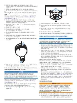
Updating the Device Software
Before you can update the software, you must obtain a
software-update memory card or load the latest software onto a
memory card.
1
Turn on the chartplotter.
2
After the home screen appears, insert the memory card into
the card slot.
NOTE:
In order for the software update instructions to
appear, the device must be fully booted before the card is
inserted.
3
Follow the on-screen instructions.
4
Wait several minutes while the software update process
completes.
The device returns to normal operation after the software
update process is complete.
5
Remove the memory card.
NOTE:
If the memory card is removed before the device
restarts fully, the software update is not complete.
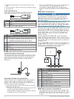
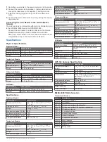
Tools Needed
• Drill and drill bits
• #2 Phillips screwdriver
• Jigsaw or rotary tool
• File and sandpaper
• Marine sealant (optional)
Mounting the Components
Mounting Considerations
NOTICE
This device should be mounted in a location that is not exposed
to extreme temperatures or conditions. The temperature range
for this device is listed in the product specifications. Extended
exposure to temperatures exceeding the specified temperature
range, in storage or operating conditions, may cause device
failure. Extreme-temperature-induced damage and related
consequences are not covered by the warranty.
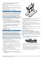
Using the included hardware and template, you can mount the
device using one of two methods. You can use the included
bracket and hardware to bail mount the device, or you can use
the included template and hardware to flush mount the device in
the dashboard. If you want to mount the device using an
alternative method where it appears flat with the front of the
dashboard, you must purchase a flat-mount kit (sold separately,
with professional installation recommended) from your Garmin
®
dealer.
When selecting a mounting location, observe these
considerations.
NOTE:
Not all mounting methods are available for all device
models. See the specific mounting-type section for more details
about your model.
• The location should provide optimal viewing as you operate
your boat.
• The location should allow for easy access to all device
interfaces, such as the keypad, touchscreen, and card
reader, if applicable.
• The location must be strong enough to support the weight of
the device and protect it from excessive vibration or shock.
• To avoid interference with a magnetic compass, the device
should not be installed closer to a compass than the
compass-safe distance value listed in the product
specifications.
• The location must allow room for the routing and connection
of all cables.
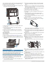
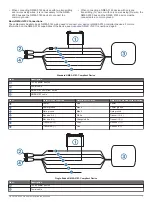
Bail Mounting the Device
NOTICE
If you are mounting the bracket on fiberglass with screws, it is
recommended to use a countersink bit to drill a clearance
counterbore through only the top gel-coat layer. This will help to
avoid any cracking in the gel-coat layer when the screws are
tightened.
The bail-mounting hardware (screws and washers or nuts,
washers, and bolts) is not included. The holes on the bail-mount
bracket are
5
/
16
in. (7.9 mm) in diameter. Before you can bail
mount the device, you must choose mounting hardware that fits
the holes in the bail-mount bracket and securely attaches it to
your specific mounting surface. The size of the pilot hole
required depends on the mounting hardware you choose.
TA-2013/402
GUID-A5780D3E-B2B0-4C60-8835-94BCF0D13E14 v4
July 2020


