background image

GPSMAP

®

 84XX/86XX/87XX

Owner’s Manual

Summary of Contents for GPSMAP 86 Series

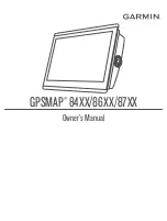
Page 1: ...GPSMAP 84XX 86XX 87XX Owner sManual...

Page 2: ...tries The BLUETOOTH word mark and logos are owned by the Bluetooth SIG Inc and any use of such marks by Garmin is under license Blu Ray is a registered trademark of the Blu ray Disc Association Chrome...

Page 3: ...Combination Page 15 Adding a SmartMode Layout 16 Customizing the Layout of a SmartMode or Combination Page 16 Deleting a Combination Page 16 Customizing the Data Overlays 17 Resetting the Station Lay...

Page 4: ...ystem 34 AIS Targeting Symbols 35 Heading and Projected Course of Activated AIS Targets 36 Activating a Target for an AIS Vessel 36 Setting the Safe Zone Collision Alarm 37 Viewing a List of AIS and M...

Page 5: ...Track 60 Deleting All Saved Tracks 61 Retracing the Active Track 61 Clearing the Active Track 61 Managing the Track Log Memory During Recording 61 Configuring the Recording Interval of the Track Log...

Page 6: ...and FrontV Sonar Settings 90 RealV Appearance Settings 92 Panoptix Transducer Installation Settings 92 LiveScope and Perspective Sonar Settings 94 LiveScope and Perspective Sonar Setup 94 LiveScope a...

Page 7: ...e Autopilot Controls on a Garmin Watch 112 Customizing the Autopilot Button Actions 112 Controlling the Autopilot with a GRID 20 Remote Control 112 Reactor Autopilot Remote Control 112 Pairing a React...

Page 8: ...Trip Gauges 130 Viewing Graphs 130 Setting the Graph Range and Time Scales 130 Disabling Graph Filtering 131 Battery Management 131 Setting Up the Battery Management Page 131 inReach Messages 131 Conn...

Page 9: ...nging the Tuning Mode 147 Presets 147 DAB Playback 147 Setting the DAB Tuner Region 147 Scanning for DAB Stations 147 Changing DAB Stations 148 DAB Presets 148 SiriusXM Satellite Radio 148 Locating a...

Page 10: ...Screen 167 Changing the Surround View Camera Layout 167 Showing and Hiding the Visual Bumper 167 Adjusting the Visual Bumper 167 Showing the Distance Marker 167 Surround View Camera Movement Control 1...

Page 11: ...for a Connected Computer 8700 Model 188 Controlling a Computer with the Chartplotter 189 Cleaning the Screen 189 Viewing Images on a Memory card 190 Screenshots 190 Capturing Screenshots 190 Copying...

Page 12: ......

Page 13: ...pport pages will provide answers to frequently asked support questions and you can download software and chart updates There is also contact information to Garmin support should you have any questions...

Page 14: ...croll Pinch two fingers together to zoom out Spread two fingers apart to zoom in On Screen Buttons These on screen buttons may be displayed on some screens and functions Some buttons are accessible on...

Page 15: ...uto Guidance route to the destination Begins navigation Ends navigation Stops and starts radar transmission Opens the radar gain adjustment menu Opens the radar sea clutter adjustment menu Opens the r...

Page 16: ...xsv model is shown below 2 microSD memory card slots 32 GB max NETWORK Garmin Marine Network HDMI IN HDMI in HDMI OUT HDMI out CVBS IN Composite video in AUDIO NMEA 0183 and audio out POWER Power USB...

Page 17: ...Power NETWORK Garmin Marine Network HDMI IN HDMI in HDMI OUT HDMI out CVBS IN Composite video in NMEA 0183 NMEA 0183 and audio out USB Micro USB to connect a compatible Garmin card reader or to connec...

Page 18: ...in Status LED Power ground Power button NMEA 0183 NMEA 0183 and audio out USB HOST Micro USB output for connecting a touchscreen monitor USB OTG Micro USB input from compatible Garmin card reader1 com...

Page 19: ...to open additional options such as adjusting the backlight Press and select Power Turn Off System or hold until the Turn Off System bar fills to turn off the chartplotter when available Press and sele...

Page 20: ...features of your chartplotter not all feature buttons are visible are on the home screen Swipe right or left to view the additional feature buttons On some menu buttons select the button to enable the...

Page 21: ...recommended An 8 GB memory card is included with GPSMAP 8x10 8x12 8x16 models Model Memory Card Location Memory Card Type 8x10 Back of the device microSD 8x12 Back of the device microSD 8x16 Back of t...

Page 22: ...n until it clicks 4 Close the card reader door Acquiring GPS Satellite Signals The device may need a clear view of the sky to acquire satellite signals The time and date are set automatically based on...

Page 23: ...lable categories tabs you may need to click and drag a tab to scroll left or right The SmartMode items are geared toward an activity such as cruising or docking When a SmartMode button is selected fro...

Page 24: ...pe to the left or right To remove a feature from the Pinned category press and hold the feature to remove select Remove Pin Yes Rearranging the Category Items You can customize the screen by rearrangi...

Page 25: ...a main page such as a chart the menu bar collapses down 2 Swipe the screen from the bottom up to show the menu bar again Setting the Vessel Type You can select your boat type to configure the chartpl...

Page 26: ...wise you must turn on the chartplotter by pressing Select Settings System Auto Power Up NOTE When Auto Power Up is On and the chartplotter is turned off using and power is removed and reapplied within...

Page 27: ...an create a custom combination page to suit your needs 1 Select Combo Add Combo 2 Select a window 3 Select a function for the window 4 Repeat these steps for each window of the page 5 Hold a window to...

Page 28: ...re interacting with the change appears only on that display except for the SmartMode name and symbol When you change the SmartMode name or symbol for the layout the new name or symbol appears on all d...

Page 29: ...view You can use particular presets to optimize groups of settings for your activity For example some settings might be optimal for when you are fishing and others might be optimal for when you are c...

Page 30: ...et manufacturers often list these as HD Voice or Wideband Speech headsets A list of supported headsets is available at support garmin com marine Pairing a Wireless Headset with a Garmin Chartplotter 1...

Page 31: ...ness Lowers the display brightness Automatic Brightness Enables automatic display brightness adjustment Sleep Display Puts the display to sleep Wake Display Wakes the display Show Traditional Sonar Op...

Page 32: ...e Lower Volume Lowers the media volume Raise Volume Raises the media volume Weather and Condition Functions Voice Command Function What is the water temperature Replies with the present water temperat...

Page 33: ...must connect it to the Garmin Marine Network 1 Select Settings System Station Information GRID Pairing Add 2 Select an action On the GRID remote input device press SELECT On the GRID 20 remote input d...

Page 34: ...waypoint or navigating a specific route and send that waypoint or route to the GPSMAP device Yes Yes Getting Started with the ActiveCaptain App You can connect a mobile device to the GPSMAP device us...

Page 35: ...otifications WARNING Do not read or reply to notifications while operating the vessel Failure to pay attention to the conditions on the water can result in vessel damage personal injury or death Befor...

Page 36: ...the chartplotter used at the helm 1 From the chartplotter you want notifications to be private select ActiveCaptain Smart Notifications 2 Select an option To turn off pop up notifications on this char...

Page 37: ...subscription allows you to access the latest chart updates and additional content using the ActiveCaptain mobile app or the Garmin Express desktop app You can download updated charts and content each...

Page 38: ...Connecting a Wireless Device to the Chartplotter Before you can connect a wireless device to the chartplotter wireless network you must configure the chartplotter wireless network Setting Up the Wi F...

Page 39: ...ces Wireless Remotes GPSMAP Remote Disconnect All 2 Follow the on screen instructions Wireless Wind Sensor Connecting a Wireless Sensor to the Chartplotter You can view data from a compatible wireless...

Page 40: ...rt views that are available depend on the map data and accessories used NOTE 3D chart views are available with premium charts in some areas You can access the charts and 3D chart views by selecting Ch...

Page 41: ...art Chart Symbols This table contains some of the common symbols you might see on the detailed charts Icon Description Buoy Information Marine services Tide station Current station Overhead photo avai...

Page 42: ...bject on the Navigation chart or the Fishing chart 1 From the Navigation chart or Fishing chart select a location or object A list of options appears The options that appear vary based on the location...

Page 43: ...se visual sightings and steer to avoid land shallow water and other dangerous objects NOTE The Fishing chart is available with premium charts in some areas NOTE Auto Guidance is available with premium...

Page 44: ...the chart Fishing Charts Shows the chart with enhanced bottom contours and without navigational data This chart works well for offshore deep sea fishing High Resolution Satellite Imagery Provides hig...

Page 45: ...You must also enable animated icons in the chart settings Showing Tides and Current Indicators page 33 An indicator for a tide station appears on the chart as a vertical bar graph with an arrow A red...

Page 46: ...the chart setup Chart Layers page 40 NOTE This feature is available with premium charts in some areas You can use aerial photographs of landmarks marinas and harbors to help orient yourself to your s...

Page 47: ...while an alarm sounds and a message banner appears After the alarm has been acknowledged a solid red triangle with a red line attached to it indicates the location and the heading of the target If th...

Page 48: ...ing line The length of the barb does not change When course over ground and heading information are provided by an activated AIS target but rate of turn information is not provided the projected cours...

Page 49: ...bled but the object is still labeled as dangerous on the screen 2 Select Range and select a distance for the safe zone radius around your vessel 3 Select Time To and select a time at which the alarm w...

Page 50: ...tion You can view AIS ATONs on the chart when the chartplotter is connected to a compatible AIS radio To show AIS ATONs from a chart select Options Layers Chart Navaid ATONs You can view more informat...

Page 51: ...Transmission lost Transmission test Appears when a vessel initiates a test of their distress signal device and does not represent a true emergency Transmission test lost Enabling AIS Transmission Test...

Page 52: ...Settings page 41 User Data Shows and hides user data such as waypoints boundaries and tracks and opens user data lists User Data Layer Settings page 42 Other Vessels Adjusts how other vessels are sho...

Page 53: ...the Wind Rose option Vessel Icon Sets the icon that represents your present location on the chart Laylines Settings To use the laylines features you must connect a wind sensor to the chartplotter Whe...

Page 54: ...t Options Layers Water NOTE The menu may contain some settings that are not supported by your installed charts or your present location If you make changes to those settings the changes will not impac...

Page 55: ...ust from a chart select Options Layers Water Depth Shading Weather Layer Settings From the Navigation or Fishing chart select Options Layers Chart Weather From a weather chart select Options Layers Ch...

Page 56: ...ter align the vessel icon with the active track line The Heading option aligns the vessel icon with the magnetic heading The GPS Heading COG option aligns the vessel icon using GPS COG If the selected...

Page 57: ...and a speed under 16 km h 10 mph A yellow circle indicates good depth and GPS position and a speed between 16 and 32 km h 10 and 20 mph A red circle indicates poor depth or GPS position and a speed a...

Page 58: ...armin Quickdraw Community Using ActiveCaptain page 46 Downloading Garmin Quickdraw Community Maps Using ActiveCaptain You can download Garmin Quickdraw Contours maps that other users have created and...

Page 59: ...uploads Your data will not be lost Downloading Garmin Quickdraw Community Maps Using Garmin Connect You can download Garmin Quickdraw Contours maps that other users have created and shared with the Ga...

Page 60: ...ng to avoid groundings or hazards that could result in vessel damage personal injury or death The Auto Guidance feature is based on electronic chart information That data does not ensure obstacle and...

Page 61: ...to provide general route guidance or to identify proper channels and are not intended to be precisely followed Always defer to the navaids and conditions on the water when navigating to avoid groundi...

Page 62: ...You can select or to scroll through the list of nearest designations Setting and Following a Direct Course Using Go To WARNING When using Go To a direct course and a corrected course may pass over lan...

Page 63: ...stance and bearing select Enter Range Bearing and enter the information Marking a Man Overboard MOB Location 1 Hold SOS for one second 2 Select the SOS type if a VHF radio is connected 3 If necessary...

Page 64: ...lect Info User Data Waypoints 2 Select a waypoint 3 Select Review Edit Position 4 Indicate a new location for the waypoint To move the waypoint using coordinates select Enter Coordinates enter the new...

Page 65: ...Guidance is available with premium charts in some areas Before you can navigate to a waypoint you must create a waypoint 1 Select Info User Data Waypoints 2 Select a waypoint 3 Select Navigate To 4 Se...

Page 66: ...he route The starting point can be your present location or another location 3 Select Add Turn 4 Select the location of the next turn on the chart 5 Select Add Turn 6 If necessary repeat steps 4 and 5...

Page 67: ...st create and save at least one route Creating and Saving a Route page 54 1 Select Info User Data Routes NOTE Auto Guidance is available with premium charts in some areas 2 Select a route 3 Select Nav...

Page 68: ...ater or other obstacles that may be in your path All route and navigation lines displayed on the chartplotter are only intended to provide general route guidance or to identify proper channels and are...

Page 69: ...on the navigation chart and select Adjust Path 3 Select a location on the path 4 Drag the point to a new location 5 If necessary select a point and select Remove 6 Select Done Canceling an Auto Guidan...

Page 70: ...path Select Settings Preferences Navigation Auto Guidance Preferred Depth Sets the minimum water depth based on chart depth data that your boat can safely travel over NOTE The minimum water depth for...

Page 71: ...a wide clearance from obstacles in open water even if you set the Shoreline Distance setting to Near or Nearest As a result the chartplotter may not reposition the Auto Guidance line unless the desti...

Page 72: ...ve the track as a boundary Saving a Track as a Route 1 Select Info User Data Tracks Saved Tracks 2 Select a track 3 Select Review Edit Track Save as Route Browsing for and Navigating a Recorded Track...

Page 73: ...d for the most efficient use of memory 1 Select Info User Data Tracks Active Track Options Interval 2 Select an option To record the track based on a distance between points select Interval Distance C...

Page 74: ...ting the boundary For example you can set a boundary around your marina and automatically open the Docking layout when you approach the marina 1 Select Info User Data Boundaries 2 Select a boundary 3...

Page 75: ...time and after you start the race timer a predictor line appears The predictor line extends from your current location toward the start line and the laylines that extend from each pin The end point an...

Page 76: ...mer is added to the Sail Racing combination screen by default 1 From the Sail Racing combination screen select Start NOTE You can also access this from the Sailing SmartMode screen and the navigation...

Page 77: ...ter a higher number For laylines that display a higher sensitivity to changes in the boat s heading or true wind angle enter a lower number Polar Tables WARNING This feature allows you to load and use...

Page 78: ...select Target App Wind Angle To show the difference between the current boat speed and the optimal boat speed shown as speed select Polar Speed To show the difference between the current boat speed a...

Page 79: ...the keel of the boat Enter this value as a positive number If the transducer is installed at the bottom of the keel and you want to know the true depth of the water measure the distance from the tran...

Page 80: ...2000 wind sensor to the autopilot Although a NMEA 2000 wind sensor is preferred you can connect a NMEA 0183 wind sensor to the autopilot to use wind hold 1 With heading hold engaged select Options 2...

Page 81: ...ground which are helpful for casting or finding reference points Setting the Heading Line and Angle Markers The heading line is an extension drawn on the map from the bow of the boat in the direction...

Page 82: ...you can separately adjust the gain for each frequency If you do not see an arrangement of sonar views to suit your needs you can create a custom combination screen Creating a New Combination Page pag...

Page 83: ...ompatible transducers go to garmin com transducers Garmin ClearV high frequency sonar provides a detailed picture of the fishing environment around the boat in a detailed representation of structures...

Page 84: ...does provide built in SideV sonar you need a compatible SideV transducer SideV scanning sonar technology shows you a picture of what lies to the sides of the boat You can use this as a search tool to...

Page 85: ...optix Sonar Views To receive Panoptix sonar you need a compatible transducer The Panoptix sonar views allow you to see all around the boat in real time You can also watch your bait underwater and bait...

Page 86: ...is sonar view shows a two dimensional view of what is below the boat and can be used to see a bait ball and fish Panoptix down view history in a scrolling sonar view Boat Range Trails Drop shot rig Bo...

Page 87: ...LiveV Forward Sonar View This sonar view shows a two dimensional view of what is in front of the boat and can be used to see a bait ball and fish Boat Range Fish Trails Bottom Sonar Fishfinder 75...

Page 88: ...ws a three dimensional view of what is in front of the transducer This view can be used when you are stationary and you need to see the bottom and the fish approaching the boat Color legend Boat Ping...

Page 89: ...his sonar view shows a three dimensional view of what is below the transducer and can be used when you are stationary and want to see what is around your boat Color legend Boat Sonar beam Range Fish B...

Page 90: ...s a three dimensional view of what is behind your boat as you are moving and shows the entire water column in 3D from the bottom to the top of the water This view is used for finding fish Color legend...

Page 91: ...sonar decreases as your speed rises above 8 knots To see the FrontV sonar view you must install and connect a compatible transducer such as a PS21 transducer You may need to update the transducer soft...

Page 92: ...artplotter to detect the transducer automatically select the transducer to change and select Auto Detect To select the transducer manually learn the range for the installed transducer select the trans...

Page 93: ...rk You can view sonar data from a compatible external sonar module such as a GCV sonar module In addition you can view the sonar data from other chartplotters that have a built in sonar module Each ch...

Page 94: ...out until the screen returns to a full screen view Adjusting the Level of Detail You can control the level of detail and noise shown on the sonar screen either by adjusting the gain for traditional t...

Page 95: ...ly select Up or Down To use the default setting select Default Sonar Setup NOTE Not all options and settings apply to all models sounder modules and transducers These settings apply to the following t...

Page 96: ...rmation on the screen longer For most situations the Default setting provides a good balance between a quickly scrolling image and less distorted targets 1 From a sonar view select Options Sonar Setup...

Page 97: ...er surface It also allows for the display of targets near the surface that are otherwise hidden or masked by surface noise Sonar Appearance Settings From a sonar view select Options Sonar Setup Appear...

Page 98: ...ake alarms audible Sounds and Display Settings page 168 Failure to set audible alarms could lead to injury or property damage NOTE Not all options are available on all transducers From an applicable s...

Page 99: ...an option From a Traditional sonar view select Options Sonar Setup Installation From a Garmin ClearV sonar view select Options ClearV Setup Installation From a Garmin SideV sonar view select Options...

Page 100: ...element which enables you to change the frequency quickly using the presets as the water and your goals change Viewing two frequencies concurrently using the split frequency view allows you to see de...

Page 101: ...Adjusting the RealV Viewing Angle and Zoom Level You can change the viewing angle of the RealV sonar views You can also zoom in and out of the view From a RealV sonar view select an option To adjust...

Page 102: ...th Manually adjusting the range enables you to view a specified range The bottom can appear on the screen as long as it appears within the range you have set Manually reducing this option can reduce t...

Page 103: ...conds It turns red and sounds an alarm when the system detects an obstruction or the depth is less than the entered value LiveV and FrontV Appearance Settings From a LiveV or FrontV Panoptix sonar vie...

Page 104: ...ducer beam Narrow beam widths allow you to see deeper and farther Wider beam widths allow you to see more coverage area This applies to Panoptix transducers in the FrontV LiveV Down and LiveV Forward...

Page 105: ...the compass the transducer must be installed far enough away from the trolling motor to avoid magnetic interference and deployed in the water Calibration must be of sufficient quality to enable the i...

Page 106: ...view a specified range which can be useful for tracking a bottom that has large terrain changes such as a drop offs or cliffs The bottom can appear on the screen as long as it appears within the rang...

Page 107: ...n forward views compresses the forward range farther away from the boat and expands the range closer to the boat This allows you to see closer objects more clearly while keeping farther objects on the...

Page 108: ...the radar the better you will become at relying on the radar display when you really need it Radar can be useful in many situations such as avoiding collisions when you have limited visibility for ex...

Page 109: ...radar warms up and a countdown alerts you when the radar is ready 3 Select Radar 4 Select a radar mode A countdown message appears while the radar is starting up 5 Select Options Transmit Radar Stopp...

Page 110: ...er setting is configured optimally Select the shortest effective range given your reason for using radar and the present environmental conditions MotionScope Doppler Radar Technology The GMR Fantom ra...

Page 111: ...onal awareness and may not prevent collisions in all circumstances You are responsible for the safe and prudent operation of your vessel and for remaining aware of obstacles or hazards in or around th...

Page 112: ...tomatically You can acquire MARPA targets automatically based on MotionScope guard zones or boundaries 1 From a radar screen select Options Layers Other Vessels MARPA Auto Acquire 2 Select and adjust...

Page 113: ...ect Details Show To set the projected heading time for AIS activated vessels select Proj Heading and enter the time To show the tracks of AIS vessels select Trails and select the length of the track t...

Page 114: ...n the screen From a radar screen select Options Radar Options Echo Trails Clear Trails Radar Settings NOTE Not all options and settings are available on all radar and chartplotter models NOTE You can...

Page 115: ...ery bright image of the target to appear on the Radar screen This image can obscure smaller targets located near it NOTE Depending upon the radar in use the gain setting configured for use in one rada...

Page 116: ...onditions automatically Adjusting Rain Clutter on the Radar Screen You can adjust the appearance of clutter caused by rain Reducing the radar range also can minimize rain clutter Adjusting the Radar R...

Page 117: ...is connected to the network Chart Display Shows the chart under the radar image When enabled the Layers menu appears Orientation Sets the perspective of the radar display Crosstalk Rej Reduces the ap...

Page 118: ...s more than 1 degree set the front of boat offset 4 From a radar screen select Options Radar Setup Installation Front of Boat 5 Select Up or Down to adjust the offset Setting a Custom Park Position By...

Page 119: ...Configuration NOTICE To avoid damage to your boat the autopilot system should be installed and configured by a qualified marine installer Specific knowledge of marine steering and electrical systems i...

Page 120: ...ep Steering Increment 1 From the autopilot screen select Options Autopilot Setup Step Turn Size 2 Select an increment Setting the Power Saver You can adjust the level of rudder activity 1 From the aut...

Page 121: ...e is enabled You can repeat these steps to disable the feature again Autopilot Overlay Bar NOTE Not all options are available on all autopilot models Autopilot status Engages and disengages heading ho...

Page 122: ...he water is clear of obstacles The autopilot can steer the boat in preset patterns for fishing and it can perform other specialty maneuvers such as U turns and Williamson turns Following the U Turn Pa...

Page 123: ...ern Steering Cloverleaf 2 If necessary select Length and select a distance 3 Select Engage Port or Engage Starboard Setting Up and Following a Search Pattern You can use the search pattern to steer th...

Page 124: ...the joystick to the right or left to steer Reactor Autopilot Remote Control WARNING You are responsible for the safe and prudent operation of your vessel The autopilot is a tool that enhances your ca...

Page 125: ...o a helm throttle and helm control device You are responsible for the safe and prudent operation of your vessel The autopilot is a tool that enhances your capability to operate your boat It does not r...

Page 126: ...the autopilot when it reaches the end of a route The FishPoint option maintains the position but does not maintain the heading The DriftPoint option allows the boat to drift with the wind or current...

Page 127: ...stops acceleration and turns When stowing or deploying the motor be aware of slick surfaces around the motor Slipping when stowing or deploying the motor may result in injury You can connect the Force...

Page 128: ...lling motor control bar allows you to control a Force trolling motor and see the status of the motor Select an item to engage it The button illuminates when selected Select the item again to disengage...

Page 129: ...e safe operation of your boat When using the Manual setting for the Arrival Mode option you must be ready to take control of the boat Auto Power On Turns on the trolling motor when you apply power to...

Page 130: ...ssels sending position reports If you have a Garmin NMEA 2000 VHF radio connected to your chartplotter these features are also enabled The chartplotter allows you to quickly set up and send individual...

Page 131: ...from a VHF Radio When the chartplotter is connected to a compatible VHF radio with NMEA 2000 and you initiate a man overboard DSC distress call from the radio the chartplotter shows the man overboard...

Page 132: ...olor for the trail line select Trail Line Deleting a Position Report Call 1 Select Info Other Vessels DSC List 2 Select a position report call 3 Select Review Edit Clear Report Viewing Vessel Trails o...

Page 133: ...Select Info Other Vessels DSC List 2 Select a vessel or a station to call 3 Select Review Call with Radio 4 If necessary select Channel and select a new channel 5 Select Send The chartplotter sends in...

Page 134: ...n lights up on the gauges page it indicates an issue with the motor Low oil level or oil pressure alert Temperature alert Battery voltage alert Check engine alert Changing the Data Shown in a Gauge 1...

Page 135: ...e of the standard operating range select Rated Max To set the lower limit of the gauge lower than the rated minimum select Scale Min To set the upper limit of the gauge higher than the rated maximum s...

Page 136: ...elect Options Installation Status Alarms Custom 2 Select one or more engine gauge alarms to turn on or off Yamaha Engine Gauges Select Vessel YAMAHA to view the Yamaha engine gauges This screen varies...

Page 137: ...Select to set the Fish Point settings Helm Master Helm Master EX Select to set the trolling speed Helm Master Helm Master EX Mechanical RC Digital Electronic RC 6X6 6X7 Data fields Hold to replace the...

Page 138: ...Return to port soon if tightening the battery connections does not increase the battery voltage Consult your Yamaha dealer immediately NOTE Do NOT stop the engine when this alert is on If you do you m...

Page 139: ...s the friction on the steering wheel The friction adjusts automatically according to the engine speed Available on the Helm Master system equipped with a digital engine control DEC system Lock to Lock...

Page 140: ...ther data Select Vessel Mercury to view the Mercury engine gauges Engine voltage or Mercury Steering Angle2 Boat status Boat speed Fuel Transmission gear Engine speed Trim tabs Engine trim TIP To view...

Page 141: ...illed up all the fuel tanks on the vessel select Fill Up All Tanks The fuel level is set to maximum capacity If you have added less than a full tank of fuel select Add Fuel to Boat and enter the amoun...

Page 142: ...your present trip Select Info Trip Graphs Trip Resetting Trip Gauges 1 Select Info Trip Graphs Trip 2 Select an option To set all the readings for the present trip to zero select Reset Trip To set the...

Page 143: ...s on the water can result in vessel damage personal injury or death You can connect an inReach Mini device to the chartplotter to view reply to and send preset messages from the chartplotter NOTE The...

Page 144: ...tal switching system contact your Garmin dealer Adding and Editing a Digital Switching Page You can add and customize digital switching pages on the chartplotter 1 Select Vessel Switching Options Setu...

Page 145: ...Vessel Switching NMEA Standard 2 Select the switch number 3 Select Name Change Name 4 Enter a new name 5 Select Done Labeling a Switch You can provide a custom label for each switch The switch label i...

Page 146: ...g option that applies to your installation type NOTE After selecting option C the next configuration option in the cycle deactivates the interlocks so that channels 1 2 and 3 operate independently as...

Page 147: ...3 Select Power Pole Anchor After you enable the Power Pole overlay on the chartplotter you must set the Power Pole installation mode to match the Power Pole anchor installation on the boat Setting Up...

Page 148: ...an accident causing property damage serious personal injury or death With a Mercury engine configured to operate with the Mercury Helm engine control feature on the chartplotter you can enable one hel...

Page 149: ...Troll feature Disable Select to disengage the Mercury Troll feature Mercury Cruise Control WARNING You are responsible for the safe and prudent operation of your vessel Mercury Cruise Control does not...

Page 150: ...es could result in an accident causing property damage serious personal injury or death When your chartplotter is connected to a compatible Mercury engine you can view engine data using the Mercury En...

Page 151: ...engine sound On the Mercury Engine overlay select Sport Exhaust On TIP You can select Toolbars from the menu bar to quickly open the overlay TIP You can also enable the Sport Exhaust setting from the...

Page 152: ...Home Mode WARNING In the event of a steering failure Optimus Limp Home mode becomes available Limp Home mode is a system override that may severely limit your boat s control It should only be used in...

Page 153: ...w information about a current station for a specific date and time including the current speed and level of the current By default the chartplotter shows current information for the most recently view...

Page 154: ...the card slot 2 Select Info Warning Manager Save to Card Clearing All of the Messages Select Info Warning Manager Clear Warning Manager Media Player If you have a compatible stereo or stereos connect...

Page 155: ...ultiple stereo or media devices connected on a network you can select the device from which you want to play music NOTE You can play media only from sources that are connected to the stereo NOTE Not a...

Page 156: ...party stereos and stereos using Fusion Link technology the Local Zones tab allow you to adjust the volume for all of the enabled speaker zones on the connected stereo For multiple Fusion stereos conn...

Page 157: ...os and groups using the chartplotter One stereo must be connected to the chartplotter through the NMEA 2000 network See the installation instructions and owner s manual provided with your compatible F...

Page 158: ...elect Options Repeat All Select Options Browse Repeat All Setting Songs to Shuffle From the media screen select an option Select Options Shuffle Select Options Browse Shuffle Radio For instructions on...

Page 159: ...ect Tune to Channel Removing a Preset 1 From an applicable media screen select Presets 2 Select a preset from the list 3 Select Remove Current Channel DAB Playback When you connect a compatible Digita...

Page 160: ...set 2 Select Browse Presets Save Current Selecting a DAB Preset from a List 1 From the DAB media screen select Browse Presets View Presets 2 Select a preset from the list Removing DAB Presets 1 From t...

Page 161: ...s List You can save your favorite channels to the presets list 1 Select Media 2 Select the channel to save as a preset 3 Select an option If the media device is a FUSION Link capable stereo select Bro...

Page 162: ...lation Set Device Name 2 Enter a device name 3 Select Select or Done Updating the Media Player Software You can update the software on compatible connected stereos and accessories See the stereo Owner...

Page 163: ...dio For more information refer to the instructions for your satellite weather and radio equipment Weather Data Broadcasts Weather data is broadcast at different intervals for each weather feature For...

Page 164: ...nt position of a hurricane a tropical storm or a tropical depression A red line stemming from a hurricane icon indicates the projected path of the hurricane Darkened dots on the red line indicate the...

Page 165: ...ds flow counterclockwise around low pressure centers in the northern hemisphere Indicates a high pressure center which is a region of relatively higher pressure Moving away from a high pressure center...

Page 166: ...ne represents 5 knots a long line represents 10 knots and triangle represents 50 knots Wind Barb Wind Speed Calm 5 knots 10 knots 15 knots 20 knots 50 knots 65 knots Wave Height Wave Period and Wave D...

Page 167: ...chartplotter to adjust the temperature range automatically select Auto Configure The chartplotter automatically finds the lower and upper limits for the current screen and updates the temperature col...

Page 168: ...s in some areas Viewing Weather Subscription Information You can view information about the weather services you have subscribed to and how many minutes have passed since the data for each service was...

Page 169: ...r to purchase a PoE Isolation Coupler You can connect multiple supported video cameras to the Garmin Marine Network You can select and view up to four video sources at once When the cameras are connec...

Page 170: ...From the video screen select Options Video Setup Set Input Associates the camera with a video source Mirror Reverses the image like a rearview mirror Standby Places the camera in standby mode to conse...

Page 171: ...d video camera supports gesture responses you can control pan tilt zoom cameras using gestures directly on the chartplotter screen Check your camera user manual for a list of available features TIP Us...

Page 172: ...should configure the camera angle and height for the best results when using the camera tracking feature You should make small adjustments until the camera view and camera tracking performance work as...

Page 173: ...r death NOTICE In some jurisdictions it could be considered an invasion of privacy rights to take or publicly display photographs or videos of people without their permission It is your responsibility...

Page 174: ...NOTE The VIRB image shown on the chartplotter is a in a lower resolution than the VIRB action camera records To view the high resolution video view the video on a computer or television 1 Select Vess...

Page 175: ...camera into a low power mode to conserve battery power Not available on the VIRB 360 camera Video Setup Sets up the video VIRB Action Camera Video Setup Settings page 163 Edit Overlays Adjusts the dat...

Page 176: ...k into the back of the chartplotter voids your warranty These chartplotter models allow video input from HDMI video sources such as a Chromecast device You can view protected HDMI content HDCP content...

Page 177: ...lect an option To turn off the audio select Off The icon appears on the video screen To play the HDMI audio select On The icon appears on the video screen To always play the HDMI audio even when you a...

Page 178: ...in the factory To view the surround view camera screen from the home screen select Vessel Surround View Item Description Information Bird s eye view The bird s eye view is always shown on the surround...

Page 179: ...before you can adjust it 1 From the surround view camera screen select Options Visual Bumper 2 Increase or decrease the range of the visual bumper line 3 Select Back Showing the Distance Marker You ca...

Page 180: ...Auto option to allow the device to set day or night colors automatically based on the time of day Startup Image Sets the image that appears when you turn on the device Startup Layout Sets the layout...

Page 181: ...ation GRID Pairing Allows you to pair a GRID remote input device with this station Display Order Sets the order of the displays which is important when using a GRID remote input device Autopilot Enabl...

Page 182: ...the north reference 000 Magnetic sets the magnetic north as the north reference Position Format Sets the position format in which a given location reading appears Do not change this setting unless yo...

Page 183: ...ance path Select Settings Preferences Navigation Auto Guidance Preferred Depth Sets the minimum water depth based on chart depth data that your boat can safely travel over NOTE The minimum water depth...

Page 184: ...ep 6 review the placement of the Auto Guidance line and determine whether the line safely avoids known obstacles and the turns enable efficient travel Auto Guidance maintains a wide clearance from obs...

Page 185: ...NMEA 0183 while navigating Using numbers may resolve compatibility issues with older NMEA 0183 autopilots Restore Defaults Restores the NMEA 0183 settings to the original factory default values Diagn...

Page 186: ...her devices and chartplotters that are compatible with the Garmin Marine Network Select Settings Communications Marine Network Setting Alarms CAUTION The Beeper setting must be turned on to make alarm...

Page 187: ...ontV transducers Water Temp Sets an alarm to sound when the transducer reports a temperature that is 2 F 1 1 C above or below the specified temperature Contour Sets an alarm to sound when the transduc...

Page 188: ...or or a temperature capable transducer Setting the Water Temperature Offset page 178 Calibrate Water Speed Calibrates the speed sensing transducer or sensor Calibrating a Water Speed Device page 178 F...

Page 189: ...Measure the distance If the transducer is installed at the water line or anywhere above the end of the keel measure the distance from the transducer location to the keel of the boat Enter this value...

Page 190: ...o the Fuel Tank option The chartplotter uses information from the tank level sensors so you do not need to do manually enter fuel information after you fill up the tanks Fuel Capacity Allows you to en...

Page 191: ...from man overboard MOB devices AIS SART Test Enables test transmissions from Search and Rescue Transponders SART Settings that are Synced on the Garmin Marine Network Garmin ECHOMAP and GPSMAP chartp...

Page 192: ...sconnect the chartplotter from the Garmin Marine Network and select Delete Data and Reset Settings This does not affect maps or software updates Sharing and Managing User Data WARNING This feature all...

Page 193: ...the data to 4 Select an option To create a new file select Add New File and enter a name To add the information to an existing file select the file from the list and select Save to Card Updating Built...

Page 194: ...ader that is attached to the computer 2 Copy a backup file from the computer to the memory card into a folder named Garmin UserData 3 Insert a memory card into the card slot 4 Select Info User Data Da...

Page 195: ...3 You should use the Garmin Express app for faster data transfer of larger downloads and updates and to avoid possible data charges with some mobile devices Function ActiveCaptain mobile app Garmin Ex...

Page 196: ...on the memory card 4 Remove the memory card from your device 5 Open the Garmin Express app on your computer 6 Insert the memory card into your computer 7 If necessary select Get Started 8 If necessar...

Page 197: ...nutes while the update process completes 16 When prompted leave the memory card in place and restart the chartplotter 17 Remove the memory card NOTE If the memory card is removed before the device res...

Page 198: ...copied to the memory card NOTE Copying the update file onto the card may take from a few minutes up to a few hours 9 Close the Garmin Express app 10 Eject the memory card from the computer After loadi...

Page 199: ...nd two output ports 8700 black box 010 12390 21 included Four input ports and two output ports Touchscreen Controls for a Connected Computer MFD models NOTICE To prevent corrosion due to moisture you...

Page 200: ...g a touchscreen To see the computer screen you must connect the computer to the HDMI IN port and connect the touchscreen to the HDMI OUT port To control the computer using the chartplotter touchscreen...

Page 201: ...rtplotter installation instructions for connection information 1 Select Vessel Video 2 Select the HDMI source for the computer 3 Select Options USB Touch Out You can now control your computer using tw...

Page 202: ...device is not acquiring satellite signals there could be a few causes If the device has moved a large distance since the last time it has acquired satellites or has been turned off for longer than a...

Page 203: ...point location to transfer and share data from one device to the next If you have manually entered a waypoint using coordinates and the location of the point does not appear where the point should be...

Page 204: ...g IEC 60529 IPX7 The device withstands incidental exposure to water of up to 1 m for up to 30 min For more information go to www garmin com water rating Fuse 10 A 125 V fast acting Input voltage From...

Page 205: ...60529 IPX7 The device withstands incidental exposure to water of up to 1 m for up to 30 min For more information go to www garmin com water rating Fuse 10 A 125 V fast acting Input voltage From 10 to...

Page 206: ...9 IPX7 The device withstands incidental exposure to water of up to 1 m for up to 30 min For more information go to www garmin com water rating Fuse 10 A 125 V fast acting Input voltage From 10 to 32 V...

Page 207: ...Water rating IEC 60529 IPX7 The device withstands incidental exposure to water of up to 1 m for up to 30 min For more information go to www garmin com waterrating Fuse 15 A Input voltage From 10 to 3...

Page 208: ...Water rating IEC 60529 IPX7 The device withstands incidental exposure to water of up to 1 m for up to 30 min For more information go to www garmin com waterrating Fuse 15 A Input voltage From 10 to 3...

Page 209: ...um Water rating IEC 60529 IPX7 The device withstands incidental exposure to water of up to 1 m for up to 30 min For more information go to www garmin com waterrating Fuse 15 A Input voltage From 10 to...

Page 210: ...rd External card reader required not included Wireless frequency and protocols Wi Fi and ANT technologies 2 4 GHz 14 15 dBm maximum Sonar Models Specifications Specification Measurement Sonar frequenc...

Page 211: ...ol 127245 Rudder 127250 Vessel heading 127258 Magnetic variance 127488 Engine parameters Rapid update 127489 Engine parameters Dynamic 127493 Transmission parameters Dynamic 127505 Fluid level 127508...

Page 212: ...27251 Rate of turn 127252 Heave 127257 Attitude 127498 Engine parameters Static 127503 AC input status obsolete 127504 AC output status obsolete 127506 DC detailed status 127507 Charger status 127509...

Page 213: ...lass B CS static data report part A 129810 AIS class B CS static data report part B 130313 Humidity 130314 Actual pressure 130316 Temperature Extended range 130576 Trim tab status 130577 Direction dat...

Page 214: ...m output command status 65252 2814 Engine total hours of operation 65253 247 Navigation based vehicle speed 65256 517 Engine fuel temperature 1 65262 174 Engine oil temperature 1 65262 175 Engine fuel...

Page 215: ...gitude GPGSA GSA GNSS DOP and active satellites GPGSV GSV GNSS satellites in view GPRMB RMB Recommended minimum navigation information GPRMC RMC Recommended minimum specific GNSS data GPRTE RTE Routes...

Page 216: ...ng information DSE Expanded digital selective calling HDG Heading deviation and variation HDM Heading magnetic MWD Wind direction and speed MDA Meteorological composite MWV Wind speed and angle VDM AI...

Page 217: ......

Page 218: ...support garmin com GUID 25CCEC48 337E 47C0 8B89 5C35CCDB65AC v22 September 2022...

Reviews: