background image

GPSMAP

®

 10X2/12X2 SERIES

Owner’s Manual

Summary of Contents for GPSMAP1222

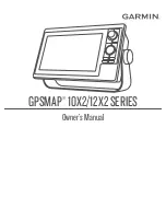
Page 1: ...GPSMAP 10X2 12X2SERIES Owner sManual...

Page 2: ...sion of Garmin Mac is a trademark of Apple Inc registered in the U S and other countries The BLUETOOTH word mark and logos are owned by the Bluetooth SIG Inc and any use of such marks by Garmin is und...

Page 3: ...12 Voice Control 12 Changing the Voice Control Language 12 Supported Headsets 12 Pairing a Wireless Headset with a Garmin Chartplotter 12 Using a Wireless Headset with a Garmin Chartplotter 12 Chartp...

Page 4: ...ivated AIS Targets 33 Viewing a List of AIS Threats 33 Activating a Target for an AIS Vessel 33 Viewing Information about a Targeted AIS Vessel 33 Deactivating a Target for an AIS Vessel 33 Showing AI...

Page 5: ...e 52 Browsing for and Navigating Parallel to a Saved Route 52 Initiating a Search Pattern 53 Deleting a Saved Route 53 Deleting All Saved Routes 53 Auto Guidance 53 Setting and Following an Auto Guida...

Page 6: ...on the Sonar Screen 71 Panoptix Sonar Views 71 LiveV Down Sonar View 72 LiveV Forward Sonar View 73 RealV 3D Forward Sonar View 74 RealV 3D Down Sonar View 75 RealV 3D Historical Sonar View 76 Garmin...

Page 7: ...formation about a MARPA tagged Object 99 Viewing a List of AIS Threats 99 Showing AIS Vessels on the Radar Screen 99 VRM and EBL 99 Showing and Adjusting the VRM and the EBL 99 Measuring the Range and...

Page 8: ...Yamaha Autopilot Overlay Bar 113 Force Trolling Motor Control 113 Connecting to a Trolling Motor 113 Adding the Trolling Motor Controls to Screens 114 Trolling Motor Control Bar 114 Trolling Motor Set...

Page 9: ...Sending a Quick Message 131 Sending a Custom Message 131 inReach SOS Calls 131 Sending an inReach SOS Call 131 Communicating with the Garmin Response Team During an SOS Call 132 Cancelling an inReach...

Page 10: ...lume Adjustment Based on Speed 148 Stereo Zones and Groups 149 Selecting the Home Zone 149 Adjusting the Zone Volume 149 Disabling a Speaker Zone 149 Creating a Group 150 Editing a Group 150 Group Syn...

Page 11: ...Weather Information near a Buoy 161 Weather Overlay 161 Viewing Weather Subscription Information 161 Viewing Video 161 Selecting a Video Source 161 Alternating Among Multiple Video Sources 161 Networ...

Page 12: ...Naming Devices and Sensors on the Network 177 The Garmin BlueNet Network and the Legacy Garmin Marine Network 177 Setting Alarms 177 Navigation Alarms 177 Setting the Anchor Drag Alarm 178 System Alar...

Page 13: ...Screenshots to a Computer 190 Troubleshooting 190 My device will not acquire GPS signals 190 My device will not turn on or keeps turning off 191 My device is not creating waypoints in the correct loc...

Page 14: ......

Page 15: ...and conditions on the water when navigating to avoid groundings or hazards that could result in vessel damage personal injury or death NOTE Not all features are available on all models The Garmin webs...

Page 16: ...light to a different function or window on a combination page Press to pan on a chart or sonar screen Press to move the cursor Press to highlight an option in a menu BACK Press to return to the previo...

Page 17: ...vary based upon the model Pictured is a GPSMAP 1212xsv model 12 PIN XDCR 12 pin transducer POWER Power Ground screw CVBS IN Composite video in ETHERNET Garmin Marine Network NMEA 2000 NMEA 2000 networ...

Page 18: ...de when available To exit standby mode select If arrows indicate not all options are visible press the indicated arrow key to view the additional options On some menu buttons select the button to enab...

Page 19: ...to acquire satellite signals The time and date are set automatically based on the GPS position 1 Turn on the device 2 Wait while the device locates satellites It may take 30 to 60 seconds to acquire...

Page 20: ...active alert or warning to view TIP The icon changes color to indicate severity The categories tabs provide quick access to the main features of your chartplotter For example the Sonar tab displays t...

Page 21: ...ed item and use the arrow keys or scroll wheel if applicable to scroll to the left or right To remove a feature from the Pinned category highlight the feature to remove press and hold the SELECT butto...

Page 22: ...you enable the Screen Lock feature Garmin Support cannot retrieve the PIN or access your device It is your responsibility to provide the PIN to anyone authorized to use the vessel 1 Select System Sou...

Page 23: ...rtplotter Recommended Startup Image Dimensions For the best fit for the startup images use an image that has the following dimensions in pixels Display resolution Image width Image height WVGA 680 200...

Page 24: ...change the layout of a page in a display you are interacting with the change appears only on that display except for the SmartMode name and symbol When you change the SmartMode name or symbol for the...

Page 25: ...imize groups of settings for your activity For example some settings might be optimal for when you are fishing and others might be optimal for when you are cruising Presets are available on some scree...

Page 26: ...nufacturers often list these as HD Voice or Wideband Speech headsets A list of supported headsets is available at support garmin com marine Pairing a Wireless Headset with a Garmin Chartplotter 1 On t...

Page 27: ...radar screen Show Sonar Opens the sonar screen Zoom In Zooms in Zoom Out Zooms out Raise Brightness Raises the display brightness Lower Brightness Lowers the display brightness Automatic Brightness E...

Page 28: ...ck Mute Mutes the media volume Unmute Unmutes the media volume Lower Volume Lowers the media volume Raise Volume Raises the media volume Weather and Condition Functions Voice Command Function What is...

Page 29: ...ar gain to the lowest setting Automatic Radar Gain Bird Sets the automatic radar gain to the setting best for locating birds Manual Radar Gain Sets the radar gain to the last manual setting Radar Rain...

Page 30: ...eScope down sonar screen Show Live Scope Forward Opens the LiveScope forward sonar screen Show Live View Opens the LiveV sonar screen Show Live View Down Opens the LiveV down sonar screen Show Live Vi...

Page 31: ...ress SELECT Rotating the GRID Remote Input Device For certain installation situations you can rotate the orientation of the GRID device NOTE This is not applicable to the GRID 20 device 1 Select Commu...

Page 32: ...tarted from the ActiveCaptain app will update only legacy Garmin Marine Network devices and none of the Garmin BlueNet devices will be updated Inserting the ActiveCaptain memory card into a Garmin Blu...

Page 33: ...d page 184 Be sure the card is inserted each time you want to use the ActiveCaptain feature 6 From the application store on your mobile device install and open the ActiveCaptain app TIP You can scan t...

Page 34: ...ature Enabling Smart Notifications page 19 When the Smart Notifications feature is enabled and your mobile device receives a notification a pop up notification appears on the GPSMAP screen briefly You...

Page 35: ...me and conserve storage space you can download only the areas of the chart you need After you download a chart or area for the first time updates are automatic each time you open ActiveCaptain If you...

Page 36: ...trouble finding or connecting to a device or if you experience interference 1 Select Communications Wi Fi Network Advanced Channel 2 Enter a new channel You do not need to change the wireless channel...

Page 37: ...grees clockwise around the mast by which the sensor points away from the center of the front of the boat If the sensor is facing starboard the angle should be between 1 and 180 degrees If the sensor i...

Page 38: ...ith premium charts in some areas Perspective 3D Provides a view from above and behind the boat according to your course and provides a visual navigation aid This view is helpful when navigating tricky...

Page 39: ...eCaptain app to the chartplotter to complete the activation process The ActiveCaptain app activates the subscription automatically after it connects to the internet and then to the chartplotter The Ac...

Page 40: ...rt Symbols This table contains some of the common symbols you might see on the detailed charts Icon Description Buoy Information Marine services Tide station Current station Overhead photo available P...

Page 41: ...rt select a location or object 2 Select Create Waypoint Viewing Location and Object Information on a Chart You can view information such as tide current celestial chart notes or local services about a...

Page 42: ...se visual sightings and steer to avoid land shallow water and other dangerous objects NOTE The Fishing chart is available with premium charts in some areas NOTE Auto Guidance is available with premium...

Page 43: ...tures using the ActiveCaptain app Activating a Marine Chart Subscription page 25 Mariner s Eye 3D Provides a view from above and behind the boat for a three dimensional navigation aid Fish Eye 3D Prov...

Page 44: ...onsibility to heed all posted water related guidance to remain aware of your surroundings and to use safe judgment in on and around the water at all times Failure to heed this warning could result in...

Page 45: ...Range Yellow 0 to 1 knot Orange 1 to 2 knots Red 2 or more knots Showing Tides and Current Indicators NOTE This feature is available with premium charts in some areas You can show static or animated t...

Page 46: ...ection in which the triangle is pointing indicates the direction in which the AIS vessel is moving Target is selected Target is activated The target appears larger on the chart A green line attached t...

Page 47: ...which is also based on the rate of turn information is indicated by the direction of the barb at the end of the heading line The length of the barb does not change When course over ground and heading...

Page 48: ...le chartplotter The safe zone collision alarm is used for AIS vessels When a radar is connected to the same network you can also use the safe zone collision alarm for MARPA targets The safe zone is us...

Page 49: ...cation You can view AIS ATONs on the chart when the chartplotter is connected to a compatible AIS radio To show AIS ATONs from a chart select MENU Layers Chart Navaid ATONs You can view more informati...

Page 50: ...vigation Transmission lost Transmission test Appears when a vessel initiates a test of their distress signal device and does not represent a true emergency Transmission test lost Enabling AIS Transmis...

Page 51: ...ings page 38 Manage User Data Shows and hides user data such as waypoints boundaries and tracks and opens user data lists User Data Layer Settings page 39 Other Vessels Adjusts how other vessels are s...

Page 52: ...se option Vessel Icon Sets the icon that represents your present location on the chart Laylines Settings To use the laylines features you must connect a wind sensor to the chartplotter When in sailing...

Page 53: ...tings From a chart select MENU Layers Water NOTE The menu may contain some settings that are not supported by your installed charts or your present location If you make changes to those settings the c...

Page 54: ...adjust from a chart select MENU Layers Water Depth Shading Weather Layer Settings From the Navigation or Fishing chart select MENU Layers Chart Weather From a weather chart select MENU Layers Chart W...

Page 55: ...ter align the vessel icon with the active track line The Heading option aligns the vessel icon with the magnetic heading The GPS Heading COG option aligns the vessel icon using GPS COG If the selected...

Page 56: ...ion and a speed under 16 km h 10 mph A yellow circle indicates good depth and GPS position and a speed between 16 and 32 km h 10 and 20 mph A red circle indicates poor depth or GPS position and a spee...

Page 57: ...armin Quickdraw Community Using ActiveCaptain page 43 Downloading Garmin Quickdraw Community Maps Using ActiveCaptain You can download Garmin Quickdraw Contours maps that other users have created and...

Page 58: ...uploads Your data will not be lost Downloading Garmin Quickdraw Community Maps Using Garmin Connect You can download Garmin Quickdraw Contours maps that other users have created and shared with the Ga...

Page 59: ...to avoid groundings or hazards that could result in vessel damage personal injury or death The Auto Guidance feature is based on electronic chart information That data does not ensure obstacle and bo...

Page 60: ...to provide general route guidance or to identify proper channels and are not intended to be precisely followed Always defer to the navaids and conditions on the water when navigating to avoid groundi...

Page 61: ...wing a Direct Course Using Go To WARNING When using Go To a direct course and a corrected course may pass over land or shallow water Use visual sightings and steer to avoid land shallow water and othe...

Page 62: ...use the chartplotter to mark a man overboard or SOS location and immediately begin navigating to the marked location If you have a VHF radio connected to the chartplotter you can also broadcast the SO...

Page 63: ...lect NAV INFO Waypoints 2 Select a waypoint 3 Select Review Edit Position 4 Indicate a new location for the waypoint To move the waypoint using coordinates select Enter Coordinates enter the new coord...

Page 64: ...Guidance is available with premium charts in some areas Before you can navigate to a waypoint you must create a waypoint 1 Select NAV INFO Waypoints 2 Select a waypoint 3 Select Navigate To 4 Select a...

Page 65: ...he route The starting point can be your present location or another location 3 Select Add Turn 4 Select the location of the next turn on the chart 5 Select Add Turn 6 If necessary repeat steps 4 and 5...

Page 66: ...st create and save at least one route Creating and Saving a Route page 51 1 Select NAV INFO Routes Auto Guidance NOTE Auto Guidance is available with premium charts in some areas 2 Select a route 3 Se...

Page 67: ...d any land shallow water or other obstacles that may be in your path All route and navigation lines displayed on the chartplotter are only intended to provide general route guidance or to identify pro...

Page 68: ...on the navigation chart and select Adjust Path 3 Select a location on the path 4 Use the arrow keys to move the point to a new location 5 If necessary select a point and select Remove 6 Select Done Ca...

Page 69: ...ance path Select Preferences Navigation Auto Guidance Preferred Depth Sets the minimum water depth based on chart depth data that your boat can safely travel over NOTE The minimum water depth for the...

Page 70: ...e clearance from obstacles in open water even if you set the Shoreline Distance setting to Near or Nearest As a result the chartplotter may not reposition the Auto Guidance line unless the destination...

Page 71: ...k as a Route 1 Select NAV INFO Tracks Saved Tracks 2 Select a track 3 Select Review Edit Track Save as Route Browsing for and Navigating a Recorded Track Before you can browse a list of tracks and nav...

Page 72: ...the track based on a distance between points select Distance Change and enter the distance To record the track based on a time interval select Time Change and enter the time interval To record the tr...

Page 73: ...ng the boundary For example you can set a boundary around your marina and automatically open the Docking layout when you approach the marina 1 Select NAV INFO Manage User Data Boundaries 2 Select a bo...

Page 74: ...ime and after you start the race timer a predictor line appears The predictor line extends from your current location toward the start line and the laylines that extend from each pin The end point and...

Page 75: ...mer is added to the Sail Racing combination screen by default 1 From the Sail Racing combination screen select Start NOTE You can also access this from the Sailing SmartMode screen and the navigation...

Page 76: ...e windward sailing angle Leeward Ang Allows you to set a layline based on the leeward sailing angle Tide Correction Corrects the laylines based on the tide Layline Filter Filters the layline data base...

Page 77: ...MENU Edit Overlays 3 Select the data field to change 4 Select Sailing 5 Select the polar data to display in the data field To show the boat speed from the polar table at the current true wind speed a...

Page 78: ...Measure the distance If the transducer is installed at the water line or anywhere above the end of the keel measure the distance from the transducer location to the keel of the boat Enter this value a...

Page 79: ...der while tacking and gybing Wind Hold You can set the autopilot to maintain a specific bearing relative to the apparent or true wind angle You must connect a compatible wind sensor the same NMEA 2000...

Page 80: ...gaged To adjust the wind hold angle in increments of 1 select 1 or 1 NOTE Holding 1 or 1 for a few seconds automatically transitions the autopilot from Wind Hold to Heading Hold and initiates rudder s...

Page 81: ...hen a heading sensor is connected 1 From a chart select MENU Layers My Vessel Heading Line Angle Markers 2 If necessary select Source and select an option To automatically use the available source sel...

Page 82: ...not see an arrangement of sonar views to suit your needs you can create a custom combination screen Creating a New Combination Page page 9 You can also add sonar views to SmartMode layouts Adding a S...

Page 83: ...ompatible transducers go to garmin com transducers Garmin ClearV high frequency sonar provides a detailed picture of the fishing environment around the boat in a detailed representation of structures...

Page 84: ...del does provide built in SideV sonar you need a compatible SideV transducer SideV scanning sonar technology shows you a picture of what lies to the sides of the boat You can use this as a search tool...

Page 85: ...optix Sonar Views To receive Panoptix sonar you need a compatible transducer The Panoptix sonar views allow you to see all around the boat in real time You can also watch your bait underwater and bait...

Page 86: ...is sonar view shows a two dimensional view of what is below the boat and can be used to see a bait ball and fish Panoptix down view history in a scrolling sonar view Boat Range Trails Drop shot rig Bo...

Page 87: ...LiveV Forward Sonar View This sonar view shows a two dimensional view of what is in front of the boat and can be used to see a bait ball and fish Boat Range Fish Trails Bottom Sonar Fishfinder 73...

Page 88: ...ws a three dimensional view of what is in front of the transducer This view can be used when you are stationary and you need to see the bottom and the fish approaching the boat Color legend Boat Ping...

Page 89: ...his sonar view shows a three dimensional view of what is below the transducer and can be used when you are stationary and want to see what is around your boat Color legend Boat Sonar beam Range Fish B...

Page 90: ...s a three dimensional view of what is behind your boat as you are moving and shows the entire water column in 3D from the bottom to the top of the water This view is used for finding fish Color legend...

Page 91: ...FrontV sonar decreases as your speed rises above 8 knots To see the Garmin FrontV sonar view you must install and connect a compatible transducer such as a PS21 transducer You may need to update the t...

Page 92: ...otter to detect the transducer automatically select the transducer to change and select Auto Detect To select the transducer manually learn the range for the installed transducer select the transducer...

Page 93: ...he Garmin Marine Network You can view sonar data from a compatible external sonar module such as a GCV sonar module In addition you can view the sonar data from other chartplotters that have a built i...

Page 94: ...nob 1 From the sonar view press the knob to switch between Range and Gain or Brightness The visual representation of the knob on the screen indicates the setting you are adjusting and the current leve...

Page 95: ...ngs page 85 Installation Configures the transducer Transducer Installation Settings page 85 Setting the Zoom Level on the Sonar Screen 1 From a sonar view select MENU Zoom Mode 2 Select an option To s...

Page 96: ...ou can adjust the range of the depth scale for traditional and Garmin ClearV sonar views You can adjust the range of the width scale for the SideV sonar view Allowing the device to adjust the range au...

Page 97: ...er surface It also allows for the display of targets near the surface that are otherwise hidden or masked by surface noise Sonar Appearance Settings From a sonar view select MENU Sonar Setup Appearanc...

Page 98: ...ke alarms audible Sounds and Display Settings page 171 Failure to set audible alarms could lead to injury or property damage NOTE Not all options are available on all transducers From an applicable so...

Page 99: ...rV Setup Installation From a Garmin SideV sonar view select MENU SideV Setup Installation Transmit Rate Sets the length of time between sonar pings Increasing the transmit rate increases the scroll sp...

Page 100: ...cer element which enables you to change the frequency quickly using the presets as the water and your goals change Viewing two frequencies concurrently using the split frequency view allows you to see...

Page 101: ...scope above shows fish returns and a soft bottom return 1 From a sonar view select MENU Sonar Setup Appearance A Scope 2 If necessary select Peak Hold to adjust the length of time the sonar returns a...

Page 102: ...ally adjusting the range enables you to view a specified range The bottom can appear on the screen as long as it appears within the range you have set Manually reducing this option can reduce the effe...

Page 103: ...react 10 seconds It turns red and sounds an alarm when the system detects an obstruction or the depth is less than the entered value LiveV and Garmin FrontV Appearance Settings From a LiveV or Garmin...

Page 104: ...er beam Narrow beam widths allow you to see deeper and farther Wider beam widths allow you to see more coverage area This applies to Panoptix transducers in the Garmin FrontV LiveV Down and LiveV Forw...

Page 105: ...ate the compass the transducer must be installed far enough away from the trolling motor to avoid magnetic interference and deployed in the water Calibration must be of sufficient quality to enable th...

Page 106: ...view a specified range which can be useful for tracking a bottom that has large terrain changes such as a drop offs or cliffs The bottom can appear on the screen as long as it appears within the rang...

Page 107: ...forward views compresses the forward range farther away from the boat and expands the range closer to the boat This allows you to see closer objects more clearly while keeping farther objects on the s...

Page 108: ...the radar the better you will become at relying on the radar display when you really need it Radar can be useful in many situations such as avoiding collisions when you have limited visibility for ex...

Page 109: ...ry the radar warms up and a countdown alerts you when the radar is ready 3 Select Radar 4 Select a radar mode A countdown message appears while the radar is starting up 5 Select MENU Transmit Radar St...

Page 110: ...enable you to view information about nearby objects more effectively if the rain clutter setting is configured optimally Select the shortest effective range given your reason for using radar and the...

Page 111: ...e boundaries of the guard zone you must enable a guard zone Enabling a Guard Zone page 97 You can define a circular guard zone that completely surrounds your boat 1 From a radar screen select MENU Rad...

Page 112: ...has been acquired A solid green ring indicates the location of a target that the radar has locked onto A dashed green line attached to the circle indicates the projected course over ground or the GPS...

Page 113: ...every other radar mode The details and projected heading settings configured for one radar mode are applied to every other radar mode and to the Radar overlay 1 From a Radar screen or the Radar overla...

Page 114: ...e the settings configured for use in one radar mode may or may not be applied to other radar modes or to the radar overlay NOTE This feature is not available on xHD open array or HD HD radome models T...

Page 115: ...ain until the targets begin to blink 5 Select Up to raise the gain until the boats land or other targets appear steadily lit on the Radar screen 6 Minimize the appearance of nearby large objects if ne...

Page 116: ...conditions automatically Adjusting Rain Clutter on the Radar Screen You can adjust the appearance of clutter caused by rain Reducing the radar range also can minimize rain clutter Adjusting the Radar...

Page 117: ...is connected to the network Chart Display Shows the chart under the radar image When enabled the Layers menu appears Orientation Sets the perspective of the radar display Crosstalk Rej Reduces the app...

Page 118: ...deviation is more than 1 degree set the front of boat offset 4 From a radar screen select MENU Radar Setup Installation Front of Boat 5 Select Up or Down to adjust the offset Setting a Custom Park Po...

Page 119: ...t Configuration NOTICE To avoid damage to your boat the autopilot system should be installed and configured by a qualified marine installer Specific knowledge of marine steering and electrical systems...

Page 120: ...Step Steering Increment 1 From the autopilot screen select MENU Autopilot Setup Step Turn Size 2 Select an increment Setting the Power Saver You can adjust the level of rudder activity 1 From the aut...

Page 121: ...is enabled You can repeat these steps to disable the feature again Autopilot Overlay Bar NOTE Not all options are available on all autopilot models Autopilot status Engages and disengages heading hold...

Page 122: ...ain the water is clear of obstacles The autopilot can steer the boat in preset patterns for fishing and it can perform other specialty maneuvers such as U turns and Williamson turns Following the U Tu...

Page 123: ...n Steering Cloverleaf 2 If necessary select Length and select a distance 3 Select Engage Port or Engage Starboard Setting Up and Following a Search Pattern You can use the search pattern to steer the...

Page 124: ...in the combo to make it full screen before you are able to use the GRID 20 remote control Press the knob to change the mode While in step steering mode turn the knob to steer Each turn of the knob pr...

Page 125: ...slot 11 Select Communications Wireless Devices Autopilot Remote Update Software Yamaha Autopilot WARNING You can use the autopilot feature only at a station installed next to a helm throttle and helm...

Page 126: ...the autopilot when it reaches the end of a route The FishPoint option maintains the position but does not maintain the heading The DriftPoint option allows the boat to drift with the wind or current w...

Page 127: ...den stops acceleration and turns When stowing or deploying the motor be aware of slick surfaces around the motor Slipping when stowing or deploying the motor may result in injury You can connect the F...

Page 128: ...control bar allows you to control a Force trolling motor and see the status of the motor Select an item to engage it The button illuminates when selected Select the item again to disengage it Trolling...

Page 129: ...e safe operation of your boat When using the Manual setting for the Arrival Mode option you must be ready to take control of the boat Auto Power On Turns on the trolling motor when you apply power to...

Page 130: ...tter these features are also enabled The chartplotter allows you to quickly set up and send individual routine call details to your Garmin VHF radio When you initiate a man overboard distress call fro...

Page 131: ...on the Navigation chart at the time of the DSC distress call 1 From a chart or 3D chart view select Layers Other Vessels DSC DSC List TIP You can quickly access the DSC list from the messages and warn...

Page 132: ...s Other Vessels DSC DSC List TIP You can quickly access the DSC list from the messages and warnings menu Messages and Warnings page 146 2 Select a position report call 3 Select Review Navigate To 4 Se...

Page 133: ...on which you want to communicate The radio transmits this request with your call Selecting a DSC Channel NOTE The selection of a DSC channel is limited to those channels that are available in all freq...

Page 134: ...ends information about the call to the radio 5 On your Garmin VHF radio complete the call Gauges and Graphs The gauges and graphs provide various information about the engine and environment To view t...

Page 135: ...change the layout of the gauges on the page select Change Layout To add a page to this set of gauge pages select Add Page To restore this page to the original view select Restore Default View Customi...

Page 136: ...1 From the engine gauges screen select MENU Installation Engine Selection Num Engines 2 Select First Engine 3 Select the engine to display in the first gauge 4 Repeat for the remaining engine bars En...

Page 137: ...t functions Helm Master Tank level information Hold a tank to view detailed tank level sensor information Status icons GPS signal strength Helm Master Select to set the Fish Point settings Helm Master...

Page 138: ...tor is on Serious engine damage will occur Low battery voltage Check the battery and battery connections and tighten all loose battery connections Return to port soon if tightening the battery connect...

Page 139: ...lm Master system equipped with a digital engine control DEC system Steer Friction Sets the friction on the steering wheel The friction adjusts automatically according to the engine speed Available on...

Page 140: ...ant pressure oil pressure and other data Select Vessel Mercury to view the Mercury engine gauges Engine voltage or Mercury Steering Angle1 Boat status Boat speed Fuel Transmission gear Engine speed Tr...

Page 141: ...he fuel level is set to maximum capacity If you have added less than a full tank of fuel select Add Fuel to Boat and enter the amount added To specify the total fuel in the vessel tanks select Set Tot...

Page 142: ...ind gauge appears select Change Upwind Scale and set the angles To set the maximum and minimum values that appear when the downwind close hauled wind gauge appears select Change Downwind Scale and set...

Page 143: ...chartplotter and receiving satellite signals to send and receive messages using the chartplotter Messages received and sent by the inReach device are grouped as conversations that are identified usin...

Page 144: ...ing the Garmin Messenger app or on your account at explore garmin com You cannot customize the text of check in messages only the contacts who will receive it 1 From the InReach page select Conversati...

Page 145: ...device before you use it outdoors Ensure the inReach device has a clear view of the sky when using the SOS function because this feature requires satellite access to operate properly NOTICE Some juris...

Page 146: ...u want to cancel the SOS call Digital Switching Your chartplotter can be used to monitor and control circuits when connected to a compatible digital switching system For example you can control the in...

Page 147: ...Vessel Switching NMEA Standard 2 Select the switch number 3 Select Name Change Name 4 Enter a new name 5 Select Done Labeling a Switch You can provide a custom label for each switch The switch label i...

Page 148: ...g option that applies to your installation type NOTE After selecting option C the next configuration option in the cycle deactivates the interlocks so that channels 1 2 and 3 operate independently as...

Page 149: ...3 Select Power Pole Anchor or Power Pole Charge After you enable the Power Pole overlay on the chartplotter you must set the Power Pole installation mode to match the Power Pole anchor installation on...

Page 150: ...to control both anchors simultaneously Deselect to control the anchors independently Select to fully retract the anchor Select to fully extend the anchor Hold to retract the anchor manually Release t...

Page 151: ...Anchor Lock function depending on the depth Trolling Motor Direction Control When the Power Pole anchors are deployed you can rotate the angle of the trolling motor as needed This is helpful when you...

Page 152: ...can enable one helm as the active Mercury Helm The active Mercury Helm controls the Mercury engines and Mercury chartplotter engine control overlays for example Mercury Cruise The overlays at non acti...

Page 153: ...prudent operation of your vessel Mercury Cruise Control does not steer the boat for you and does not avoid navigational hazards Failure to safely operate your boat could result in an accident causing...

Page 154: ...ssel Failure to properly maintain the engines could result in an accident causing property damage serious personal injury or death When your chartplotter is connected to a compatible Mercury engine yo...

Page 155: ...port Exhaust setting alters the engine sound On the Mercury Engine overlay select Sport Exhaust On TIP You can also enable the Sport Exhaust setting from the Mercury gauges page menu Mercury Active Tr...

Page 156: ...ble the Optimus overlay to control the Optimus system Activating the Optimus Overlay Bar page 142 When necessary the Optimus system provides messages with information instructions and alerts about fau...

Page 157: ...me Mode WARNING In the event of a steering failure Optimus Limp Home mode becomes available Limp Home mode is a system override that may severely limit your boat s control It should only be used in an...

Page 158: ...esent time indicated on the tide or current station graph as a white line You can select and to adjust the time on the tide or current station graph Present sunrise and sunset times Select to open the...

Page 159: ...overlay bar on the chartplotter shows current information for the most recently viewed current station and for the present date and time Tide and Current Overlays page 144 From the Currents overlay ba...

Page 160: ...s an active warning A window opens that shows messages and any active warnings 2 Select an option Select a message or an active warning Select All Communications Alarm History 3 If necessary select an...

Page 161: ...twork the chartplotter should automatically detect the stereos If you have a compatible third party stereo connected to the NMEA 2000 network you may be able to control the stereo using the chartplott...

Page 162: ...ls in other zones Selecting the Home Zone page 149 1 From the media screen select MENU Audio Levels 2 Select or to adjust the audio levels you want to change Muting the Media Volume 1 From the media s...

Page 163: ...connected to the chartplotter or have a stereo or stereos with multiple speaker zones connected to the chartplotter you must designate one speaker zone on one stereo as the home zone The playback and...

Page 164: ...a physical switch on the ignition wire the red wire all of the synchronized stereos in the group turn off and on together This applies to all of the synchronized stereos in the group whether or not a...

Page 165: ...and sources support the All option for the Repeat control From the media screen select an option Select MENU Repeat All Select MENU Browse Repeat All Setting Songs to Shuffle From the media screen sel...

Page 166: ...is connected to the proper DAB equipment and set to the correct tuner region DAB Playback page 152 Saving a Station as a Preset 1 From an applicable media screen tune to the station to save as a prese...

Page 167: ...ns 2 Select a station from the list Selecting a DAB Station from a Category 1 From the DAB media screen select Browse Categories 2 Select a category from the list 3 Select a station from the list DAB...

Page 168: ...st be turned on and receiving the SiriusXM signal 5 If the service is not activated within the hour go to http care siriusxm com refresh or contact SiriusXM Listener Care by phone at 1 866 635 2349 Cu...

Page 169: ...ontrol settings to their default values the passcode value is reset to 0000 1 From the media menu select Installation Factory Defaults 2 Select Yes Changing a Parental Passcode on a SiriusXM Radio Bef...

Page 170: ...dio For more information refer to the instructions for your satellite weather and radio equipment Weather Data Broadcasts Weather data is broadcast at different intervals for each weather feature For...

Page 171: ...nt position of a hurricane a tropical storm or a tropical depression A red line stemming from a hurricane icon indicates the projected path of the hurricane Darkened dots on the red line indicate the...

Page 172: ...ds flow counterclockwise around low pressure centers in the northern hemisphere Indicates a high pressure center which is a region of relatively higher pressure Moving away from a high pressure center...

Page 173: ...e represents 5 knots a long line represents 10 knots and triangle represents 50 knots Wind Barb Wind Speed Calm 5 knots 10 knots 15 knots 20 knots 50 knots 65 knots Wave Height Wave Period and Wave Di...

Page 174: ...hartplotter to adjust the temperature range automatically select Auto Configure The chartplotter automatically finds the lower and upper limits for the current screen and updates the temperature color...

Page 175: ...e Fishing chart is available with premium charts in some areas Viewing Weather Subscription Information You can view information about the weather services you have subscribed to and how many minutes...

Page 176: ...the isolation coupler is not necessary Go to garmin com for a list of compatible devices or to purchase a PoE Isolation Coupler Go to garmin com manuals bluenet for more information about Garmin BlueN...

Page 177: ...From the video screen select MENU Video Setup Set Input Associates the camera with a video source Mirror Reverses the image like a rearview mirror Standby Places the camera in standby mode to conserv...

Page 178: ...ct Aspect Standard To adjust the brightness select Brightness and select Up Down or Auto To adjust the color saturation select Saturation and select Up Down or Auto To adjust the contrast select Contr...

Page 179: ...k 4 Select Back until you return to the video screen The camera view automatically adjusts to show the specified direction as the vessel moves 5 If necessary use the arrow keys to adjust the camera an...

Page 180: ...tplotter using WPS If you are connecting a VIRB camera connect through the camera settings Connecting a VIRB Action Camera page 166 1 Set up the chartplotter s Wi Fi network Setting Up the Wi Fi Netwo...

Page 181: ...pan and tilt the VIRB 360 use the arrow keys To return the VIRB 360 view to the home position select Controlling the VIRB Action Camera Video Playback You can view VIRB action camera video and images...

Page 182: ...ize or pixel dimensions of photos Field of View Sets the zoom level Lens Mode Sets which lens or lenses the camera uses while shooting video Mirror Allows you to flip or mirror the video Rotation Allo...

Page 183: ...in the factory To view the surround view camera screen from the home screen select Vessel Surround View Item Description Information Bird s eye view The bird s eye view is always shown on the surround...

Page 184: ...ore you can adjust it 1 From the surround view camera screen select MENU Visual Bumper 2 Increase or decrease the range of the visual bumper line 3 Select BACK Showing the Distance Marker You can show...

Page 185: ...e device to display day or night colors You can select the Auto option to allow the device to set day or night colors automatically based on the time of day Startup Image Sets the image that appears w...

Page 186: ...as a stand alone individual display instead of grouping it with other displays to make a station Input Device Pairing Allows you to pair a GRID remote input device or other compatible input device wi...

Page 187: ...Sets the direction references used in calculating heading information True sets geographic north as the north reference Grid sets grid north as the north reference 000 Magnetic sets the magnetic nort...

Page 188: ...Guidance path Select Preferences Navigation Auto Guidance Preferred Depth Sets the minimum water depth based on chart depth data that your boat can safely travel over NOTE The minimum water depth for...

Page 189: ...review the placement of the Auto Guidance line and determine whether the line safely avoids known obstacles and the turns enable efficient travel Auto Guidance maintains a wide clearance from obstacle...

Page 190: ...NMEA 0183 while navigating Using numbers may resolve compatibility issues with older NMEA 0183 autopilots Restore Defaults Restores the NMEA 0183 settings to the original factory default values Diagn...

Page 191: ...onnectors and is capable of higher speeds than the previous network technology You can connect Garmin Marine Network devices to Garmin BlueNet devices to share data with one another when the network i...

Page 192: ...circumstances It is your obligation to ensure safe operation of the vessel CAUTION The Beeper setting must be turned on to make alarms audible Sounds and Display Settings page 171 Failure to set audib...

Page 193: ...anchor above the waterline The Anchor Scope value is the ratio of the length of anchor rode in use to the vertical distance from the bow of the vessel to the bottom of the water These anchor settings...

Page 194: ...sure the distance If the transducer is installed at the water line or anywhere above the end of the keel measure the distance from the transducer location to the keel of the boat Enter this value as a...

Page 195: ...e Fuel Tank option The chartplotter uses information from the tank level sensors so you do not need to do manually enter fuel information after you fill up the tanks Fuel Capacity Allows you to enter...

Page 196: ...m man overboard MOB devices AIS SART Test Enables test transmissions from Search and Rescue Transponders SART Settings that are Synced on the Garmin Marine Network Garmin ECHOMAP and GPSMAP chartplott...

Page 197: ...he chartplotter from the Garmin Marine Network and select Delete Data and Reset Settings This does not affect maps or software updates Sharing and Managing User Data WARNING This feature allows you to...

Page 198: ...r Save All to Card 3 If necessary select the memory card to copy the data to 4 Select an option To create a new file select Add New File and enter a name To add the information to an existing file sel...

Page 199: ...ta to a Computer 1 Insert a memory card into the card slot 2 Select NAV INFO Manage User Data Data Transfer Save to Card 3 Select a file name from the list or select Add New File 4 Select Save to Card...

Page 200: ...6 You should use the Garmin Express app for faster data transfer of larger downloads and updates and to avoid possible data charges with some mobile devices Function ActiveCaptain mobile app Garmin Ex...

Page 201: ...armin folder on the memory card 4 Remove the memory card from your device 5 Open the Garmin Express app on your computer 6 Insert the memory card into your computer 7 If necessary select Get Started 8...

Page 202: ...ftware Yes 15 Wait several minutes while the update process completes 16 When prompted leave the memory card in place and restart the chartplotter 17 Remove the memory card NOTE If the memory card is...

Page 203: ...pdate onto the memory card install the software on the chartplotter Updating the Device Software Using a Memory Card page 189 Updating the Device Software Using a Memory Card To update the software us...

Page 204: ...Hold HOME for at least six seconds Copying Screenshots to a Computer 1 Remove the memory card from the chartplotter and insert it into a card reader that is attached to a computer 2 From Windows Expl...

Page 205: ...waypoint location to transfer and share data from one device to the next If you have manually entered a waypoint using coordinates and the location of the point does not appear where the point should...

Page 206: ...ic and die cast aluminum Water rating IEC 60529 IPX72 Fuse 6 A 125 V fast acting Input voltage From 10 to 32 Vdc Max power usage at 10 Vdc 32 4 W Typical current draw at 12 Vdc 1 9 A Max current draw...

Page 207: ...0 LEN 9 Vdc 2 NMEA 2000 draw 75 mA max Max waypoints 5 000 Max routes 100 Max active track points 50 000 points 50 saved tracks Memory card 2 SD card slots 32 GB max card size Wireless frequency and p...

Page 208: ...ol 127245 Rudder 127250 Vessel heading 127258 Magnetic variance 127488 Engine parameters Rapid update 127489 Engine parameters Dynamic 127493 Transmission parameters Dynamic 127505 Fluid level 127508...

Page 209: ...ue 126992 System time 127233 Man overboard 127251 Rate of turn 127252 Heave 127257 Attitude 127498 Engine parameters Static 127503 AC input status obsolete 127504 AC output status obsolete 127506 DC d...

Page 210: ...A 129810 AIS class B CS static data report part B 130067 Route and waypoint service Route waypoint name and position 130313 Humidity 130314 Actual pressure 130316 Temperature Extended range 130569 En...

Page 211: ...gitude GPGSA GSA GNSS DOP and active satellites GPGSV GSV GNSS satellites in view GPRMB RMB Recommended minimum navigation information GPRMC RMC Recommended minimum specific GNSS data GPRTE RTE Routes...

Page 212: ...formation DSE Expanded digital selective calling HDG Heading deviation and variation HDM Heading magnetic MWD Wind direction and speed MDA Meteorological composite MWV Wind speed and angle RTE Routes...

Page 213: ......

Page 214: ...support garmin com GUID C3CEA164 A1CB 4B15 92F2 5C04944CC6F3 v21 January 2024...

Reviews: