background image

GSD

 26 Installation Instructions

To obtain the best performance and to avoid damage to your boat, install the device according to these 
instructions.
Read all installation instructions before proceeding with the installation. If you experience difficulty during the 
installation, contact Garmin Product Support.

Important Safety Information

 WARNING

See the Important Safety and Product Information guide in the product box for product warnings and other 
important information.
You are responsible for the safe and prudent operation of your vessel. Sonar is a tool that enhances your 
awareness of the water beneath your boat. It does not relieve you of the responsibility of observing the water 
around your boat as you navigate.

 CAUTION

Failure to install and maintain this equipment in accordance with these instructions could result in damage or 
injury.
Always wear safety goggles, ear protection, and a dust mask when drilling, cutting, or sanding.

NOTICE

When drilling or cutting, always check what is on the opposite side of the surface.
This equipment must be installed by a qualified marine installer.

Transducers

A transducer is required to send and receive a sonar signal from the sounder. Proper transducer selection and 
installation are critical to the operation of the device. Because mounting locations vary, see your local Garmin 
dealer or contact Garmin Product Support for more information. Go to 

www.garmin.com/transducers

 to select a 

transducer.

Installation Preparation

NOTICE

This device must be installed according to these instructions to get the best possible performance. If you 
experience difficulty with the installation, contact Garmin Product Support.

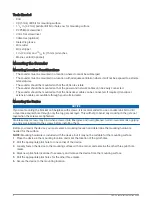
Because every boat is different, you must carefully plan the GSD 26 sounder installation.
Select a mounting location.
Mount the sounder.
Connect the sounder to the Garmin Marine Network and to power.
Connect the sounder to the transducer.

TA-2013/325

GUID-CD9D5480-1EC6-4A73-AB59-0037B3321584 v5

May 2022

Summary of Contents for GSD 26

Page 1: ...ection and a dust mask when drilling cutting or sanding NOTICE When drilling or cutting always check what is on the opposite side of the surface This equipment must be installed by a qualified marine...

Page 2: ...berglass with screws it is recommended to use a countersink bit to drill a clearance counterbore through only the top gel coat layer This will help to avoid any cracking in the gel coat layer when the...

Page 3: ...gn the notch on the end of the power cable with the power port on the device and press the cable into place 6 Tighten the locking ring 7 Repeat steps 4 and 5 for the network cable and connect the devi...

Page 4: ...Transducer Wire Color Tables page 11 for specific examples of Garmin wire colors 1 Connect the uninsulated section of each wire to the terminal block using a 3 mm flat screwdriver 2 Connect the bare s...

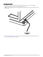
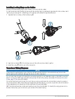
Page 5: ...is ground post to the boat water ground circuit NOTE The boat battery ground is an acceptable alternative if your vessel does not have a designated water ground circuit 2 Mount the sounder Mounting th...

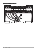
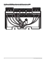
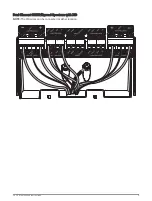
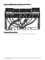
Page 6: ...e high frequency terminal block damages the device and the transducer You can use these diagrams to identify the connection points for your transducer wires on the GSD 26 terminal block Locate your CH...

Page 7: ...Single Element CHIRP Spread Spectrum GSD 26 Installation Instructions 7...

Page 8: ...Dual Element CHIRP Spread Spectrum with Temperature and XID NOTE The temperature and XID wires can be connected at either location 8 GSD 26 Installation Instructions...

Page 9: ...Dual Element CHIRP Spread Spectrum with XID NOTE The XID wires can be connected at either location GSD 26 Installation Instructions 9...

Page 10: ...Dual Element CHIRP Spread Spectrum with Separate Temperature Sensor NOTE The temperature and XID wires can be connected at either location 10 GSD 26 Installation Instructions...

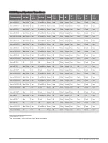
Page 11: ...Separate Speed Sensor NOTE The XID wires can be connected at either location Transducer Wire Color Tables You can use these tables to help identify wire functions on certain Garmin or Airmar transduc...

Page 12: ...1 Bare Black White Brown NA White Orange Blue Bare Black Bare Airmar B175H NA NA NA Brown NA White Orange Blue Bare Black Bare Airmar B175L Blue White Bare Black White Brown NA White Orange NA NA NA B...

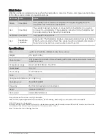
Page 13: ...ce to clear the error Specifications Size L x W x H 274 x 373 x 100 mm 10 8 x 14 7 x 3 9 in Weight 5 16 kg 11 37 lb Case material Fully gasketed aluminum and steel housing with plastic access panel wa...

Page 14: ...2014 2022 Garmin Ltd or its subsidiaries support garmin com...

Reviews: