background image


GTR 205
GNC 215

Pilot's Guide

Summary of Contents for GTR 205

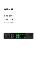
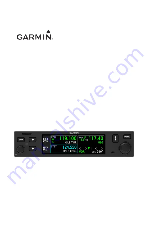
Page 1: ...GTR 205 GNC 215 Pilot s Guide...

Page 2: ...tribution of this manual or any revision hereto is strictly prohibited Garmin flyGarmin and flyGarmin com are registered trademarks of Garmin International or its subsidiaries GFC and GI 275 are trade...

Page 3: ...rmation at your own risk WARNING Always resolve any discrepancies between the display and other navigation sources when they occur During flight operations compare display indications to information f...

Page 4: ...e only to aircraft maintenance personnel To reduce RF exposure avoid installation of antenna s in areas of the aircraft that provide crew or passengers direct exposure to antenna radiation For install...

Page 5: ...Visit flyGarmin com and select Database Exclusions List NOTE The pilot operator must have access to Garmin and Jeppesen database alerts and consider their impact on the intended aircraft operation To...

Page 6: ...ord of Revision Available for Download Electronic Pilot s Guide A version of this guide saved in Adobe Acrobat Available for viewing on your computer or portable device Go to garmin com manuals REVISI...

Page 7: ...fferences dictate the GNC 215 display is shown as typical GTR 205 GNC 215 When you see It means a product name in bold e g GNC 215 the information pertains to that specific model only product names se...

Page 8: ...icable WARNING Indicates when serious injury or death will occur CAUTION Indicates when equipment damage is possible NOTE Emphasizes a point about a specific feature function or operation Insets These...

Page 9: ...190 02766 02 Rev A Pilot s Guide vii Reference Websites WEBSITE QR CODE SCAN GO Aviation Limited Warranty https www garmin com en US legal aviation limited warranty Declarations of Conformity https ww...

Page 10: ...viii Pilot s Guide 190 02766 02 Rev A INTENTIONALLY LEFT BLANK...

Page 11: ...Database from a microSD Card 2 5 Automatic Updates 2 6 Manual Updates 2 6 Database Errors 2 7 Revert to Previous Database Version 2 8 View Database Information 2 9 Active Database 2 9 Standby Database...

Page 12: ...4 3 Monitor a NAV Frequency 4 6 Find a NAV Frequency 4 7 View Navigation Data 4 9 VOR Info Distance Data 4 9 CDI 4 10 Specify an OBS Course 4 11 Respond to a NAV Alert 4 13 5 TIMERS 5 1 Enable View Ti...

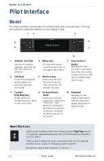
Page 13: ...1 System at a Glance OVERVIEW 1 2 PILOT INTERFACE 1 4 COMPATIBLE EQUIPMENT 1 19...

Page 14: ...employ a 3 2 high resolution color liquid crystal display They comprise the Slimline series of 1 35 by 6 25 COM radio products Each unit has 10 W of transmit power Optional 16 W of transmit power is...

Page 15: ...OM TRANSCEIVER 8 33 kHz or 25 kHz channel spacing 16 W transmit power capability1 Bearing and distance to NAVAID2 Find frequency Flight timers NVIS1 Remote COM radio frequency tuning3 Reverse frequenc...

Page 16: ...itor Key Allows monitoring of the active frequency while listening to the standby frequency 3 Transfer Flip Flop Key Swaps active and standby frequency values for the active radio 6 Volume Power Knob...

Page 17: ...for updating databases In the event there is a file corruption problem with the microSD card it may be necessary to reformat the card This can cause an issue when formatting the microSD card using ma...

Page 18: ...Keys Selections change based on the active page or function 1 GNC 215 only COMMON COMMANDS Open the system messages list A flashing icon indicates unread messages Display COM frequency search options...

Page 19: ...ude scrolling lists data fields function keys or a combination of controls Tabs are located along the left side of the menu pane Pop ups Pop ups present messages related to a function or setting that...

Page 20: ...ving cursor forward or backward within data field Scrolling menu tabs Tuning major frequency digits Inner Knob Turn Modifying individual characters in data entry field Scrolling lists Tuning minor fre...

Page 21: ...mited to Single or Inner Knob Turn Push Outer Knob Turn Only COM Standby Frequency Active GTR 205 Available knob functions Adjust COM radio volume Override automatic squelch Tune COM standby frequency...

Page 22: ...oll search categories Select frequency Add user frequency Available knob functions Scroll message list NAV Volume Active1 System Message List Active Available knob functions Adjust NAV radio volume Ac...

Page 23: ...yan border around the active feature window indicates changes in knob focus This is useful when transitioning between different control modes Knob Focus Indicator COM STBY Selected Timer Function Not...

Page 24: ...s if available When knob focus is set to the COM radio default turn the inner and outer knobs to tune the COM standby frequency TUNE THE COM EMERGENCY FREQUENCY Pushing and holding the volume squelch...

Page 25: ...s frequency search options The Select Frequency menu opens from the last viewed search result Turn the outer knob to select a search category Turn the inner knob to select a frequency waypoint or stat...

Page 26: ...y NAV frequency tuning enabled push and hold the dual concentric knob for 1 5 seconds to display NAV frequency search options Turn the outer and inner knobs to select a search category and frequency A...

Page 27: ...nobs to set a course Three way Toggle Indication AVAILABLE WITH GNC 215 Locater bars work in conjunction with the inner control knob providing a quick indication of current knob focus as you transitio...

Page 28: ...inner knob moves the locater through the available functions The COM standby frequency window is active by default Push to activate OBS timer control Push to activate NAV frequency control COM Active...

Page 29: ...nt in the slot 2 Go to the page of interest 3 Push and hold the MON key 4 With the MON key depressed push and release the top soft key The image automatically saves to the print folder in the microSD...

Page 30: ...from Morse code VOR localizer data White Active system message mode Current data and values Menu options Scales and markings Standby radio frequency non selected radio Station ID from database Magenta...

Page 31: ...iple LRUs which are installed behind the instrument panel or in a separate avionics bay Their modular design aids system maintenance and unit replacement Optional LRUs may include compatible equipment...

Page 32: ...1 20 Pilot s Guide 190 02766 02 Rev A INTENTIONALLY LEFT BLANK...

Page 33: ...2 Get Started POWER UP THE UNIT 2 2 LOAD DATABASE 2 3 CUSTOMIZE PILOT SETTINGS 2 12 VIEW SYSTEM INFORMATION 2 17...

Page 34: ...ates if a newer version is available Power Off the Unit WARNING Never attempt to power off the unit while airborne unless operational procedures dictate Read more about database update methods in Load...

Page 35: ...ase that has not reached the effective date Database that was installed prior to the last update To view active and standby databases once they are installed read View Database Information Supported D...

Page 36: ...ernal Standby storage but is deemed not yet effective At this point the pilot may remove the card The database will remain in standby until the effectivity date is reached and automatic activation can...

Page 37: ...ates the microSD card is no longer required Do not attempt to load or update the database while in flight on ground only Install or update a database using a micro SD card 1 Download a database onto a...

Page 38: ...ts effective dates1 1 Applicable only if a GPS source is present Updates occur during power up when a newer version of the database is available The same process occurs when you load a new database fo...

Page 39: ...the appropriate information tab Aviation Database Errors Visit flyGarmin com to report any discrepancies in database information These may include incorrect procedures inaccurate depictions of terrai...

Page 40: ...evert to a previous database version 1 Ensure that the card slot is empty 2 Verify that the previous database version is in standby Menu System Database Standby 3 Open the Update tab 4 Select Start DB...

Page 41: ...can view information about active and standby databases from the Database Information page MENU System Database WHERE TO FIND IT System Database Menu Selecting Active displays information about the da...

Page 42: ...Update Selecting Standby displays information about the database that is not currently in use by the system The previously installed database also appears here once an update completes Standby databas...

Page 43: ...message informs you when no valid database is available When the Navigation database is absent the radio is still usable but with reduced functionality Lost features include Waypoint names GPS based...

Page 44: ...Enable flight timer Return to basic display format1 Enable CDI option2 Setup Tab Set the display units Access COM radio settings System Tab Adjust display brightness Access database information and u...

Page 45: ...splay tab to choose a feature for the other area 1 Availability dependent upon configuration AVAILABLE WITH GNC 215 AREA AVAILABLE DISPLAY FEATURES VOR Info To From Off Standby CDI1 TMR STBY with Reve...

Page 46: ...quency Adds decoded from radial information to the active NAV frequency TMR CDI Adds an active timer to the lower right of the display Use the outer knob to select timer type or select Start Select Re...

Page 47: ...mph Kilometers km kph NAV Angle Magnetic True T Customize the display unit settings Selecting Units opens a menu of available unit types MENU Setup Units WHERE TO FIND IT Setup Units Menu To specify u...

Page 48: ...ay from going black in the event of a dimmer input failure Installer configured curves determine the amount of change in brightness that occurs in response to a control adjustment If brightness contro...

Page 49: ...s Guide 2 17 View System Information System System Info Menu View information specific to the unit and its software WHERE TO FIND IT Refer here when contacting customer service System Info Serial num...

Page 50: ...2 18 Pilot s Guide 190 02766 02 Rev A INTENTIONALLY LEFT BLANK...

Page 51: ...COM RADIO 3 2 ADJUST COM RADIO VOLUME SQUELCH 3 5 TUNE A COM FREQUENCY 3 6 MONITOR A COM FREQUENCY 3 9 FIND A COM FREQUENCY 3 10 CREATE COM USER FREQUENCIES 3 16 VIEW COM STATUS 3 19 RESPOND TO A COM...

Page 52: ...Set transceiver channel spacing Options 8 33 kHz 25 kHz default Sidetone Volume Enable offset adjustments from the COM receiver volume Options Fixed Offset Link to COM Sidetone Offset Adjust sidetone...

Page 53: ...in a region where 8 33 kHz channel spacing is available set the COM radio to 8 33 kHz to prevent the loss of any stored or recently used frequencies Turning the inner knob toggles the transceiver chan...

Page 54: ...audio spoken into the microphone that is played back in real time over the headset The offset setting determines sidetone volume for the COM during radio transmission Adjustments determine the amount...

Page 55: ...mall knob according to your preference The unit retains volume settings over power cycles Percent of Max Volume Relative Volume Indicator Push the volume squelch knob to override the automatic squelch...

Page 56: ...frequency This frequency may be set and activated at any time COM STATUS INDICATIONS Status annunciations denote active functions modes and frequency types Receiving transmission Transmitting Automat...

Page 57: ...5 seconds automatically displays frequency search options The selected STBY window turns cyan when you use the control knob to change the standby COM frequency If no action occurs the STBY window rev...

Page 58: ...3 8 Pilot s Guide 190 02766 02 Rev A COM Transfer Frequency to Active Flip Flop The transfer or flip flop function allows you to swap the active and standby frequency values Before After...

Page 59: ...nabling monitor mode allows you to listen to the standby frequency while the unit continues monitoring the active COM channel When the COM active frequency receives a signal the unit automatically swi...

Page 60: ...ol center frequencies within a 200 NM radius Nearest FSS Lists up to 20 flight service center frequencies within a 200 NM radius Nearest WX Lists up to 20 weather frequencies within a 200 NM radius Fi...

Page 61: ...UENCIES Waypoint Identifier Facility Name Bearing Distance Nearest airports include bearing and distance to field information based on GPS data A selector appears when more than one frequency type is...

Page 62: ...arch errors may display if any one of the following conditions exist Nearest Frequency Search Options The unit is configured for GPS but is not receiving a position The unit is configured for GPS but...

Page 63: ...y type for active and standby frequencies The unit verifies the displayed frequency against the database at least once per minute Frequency Type Facility Identifier denotes more than one type associat...

Page 64: ...ces in order of priority from highest 1 to lowest 3 and dependent upon certain required conditions SOURCE REQUIRED CONDITIONS 1 Proximity search of database Navigation database and GPS are present 2 R...

Page 65: ...up one to scroll down Selections do not activate until transfered to active Emergency Frequency Selection Pushing and holding either the volume knob or Flip Flop key for 0 5 seconds provides a quick m...

Page 66: ...user frequency list Controls are accessible via the Select Frequency menu 1 Open the Select Frequency menu 2 Scroll to the User category 3 Push the inner control knob to add a new frequency 4 Specify...

Page 67: ...Frequency Modify an existing user frequency Selecting a user frequency gives you the EDIT option 1 Select the user frequency from the list 2 Push the Edit soft key 3 Modify the current frequency name...

Page 68: ...from the list 2 Push the EDIT soft key 3 Select Delete From here you may Confirm deletion of the selected user frequency Select Delete Delete all COM user frequencies Select Delete All Frequencies De...

Page 69: ...tatus View COM radio transmit voltage and received noise This information is accessible via the System tab MENU System COM Status WHERE TO FIND IT System COM Status Menu This page is for reference onl...

Page 70: ...key on the microphone is stuck or accidentally left in the keyed position Push to talk function continues to transmit after releasing the key The advisory message COM MIC 1 2 key is stuck alerts for a...

Page 71: ...AV RADIO VOLUME 4 2 ACTIVATE NAV IDENT 4 2 TUNE A NAV FREQUENCY 4 3 MONITOR A NAV FREQUENCY 4 6 FIND A NAV FREQUENCY 4 7 VIEW NAVIGATION DATA 4 9 SPECIFY AN OBS COURSE 4 11 RESPOND TO A NAV ALERT 4 13...

Page 72: ...e with the inner and outer control knobs according to your preference You can adjust the volume by increments of ten outer control knob or one inner control knob Percent of Max Volume Relative Volume...

Page 73: ...t The reverse frequency look up identifier displays below the frequency value Reverse frequency look up results are based on GPS position and database information If no GPS navigator is present in the...

Page 74: ...hen the identifier is inferred from the database and current location The identifier turns green when a valid ID is decoded from Morse code Custom User NAV Frequencies User stored NAV frequencies may...

Page 75: ...knob once or twice depending on pilot settings Upon selection the standby NAV frequency window remains active for approximately 30 seconds 2 Enter a standby frequency by turning the inner and outer co...

Page 76: ...you to listen to the standby frequency while the unit continues monitoring the active NAV channel Radial Standby VOR During monitor mode A gray ID with strike through indicates that Morse ID is unava...

Page 77: ...Lists up to 20 VOR frequencies within a 200 NM radius when interfaced with a GPS receiver Nearest LOC Lists up to 20 localizer frequencies within a 200 NM radius when interfaced with a GPS receiver Ma...

Page 78: ...rch errors may display if any one of the following conditions exist Nearest Frequency Search Options The unit is configured for GPS but is not receiving a position The unit is configured for GPS but n...

Page 79: ...l and To bearing Distance to station Lateral deviationand to from indication on a CDI scale OBS course heading Depending on configuration you may view supplemental navigation data in the active and st...

Page 80: ...the center bar to be on course The CDI presents a sliding lateral deviation indicator on a horizontal scale A pointer moves left or right to portray aircraft position relative to the selected course...

Page 81: ...ing the dual concentric knob Exit entry mode by doing one of the following Push the dual concentric knob Allow entry mode to expire OBS Entry Field Active Selecting the Direct CRS soft key while the O...

Page 82: ...4 12 Pilot s Guide 190 02766 02 Rev A NAV OBS SOURCE LOST A message informs you when GNC 215 loses selected course input from the external NAV indicator When this occurs you may select OBS...

Page 83: ...ations are designed to be immediately recognizable Use an alternate method of navigation in response to a NAV radio failure Radio failures are indicated by one or more of the following Red X displays...

Page 84: ...4 14 Pilot s Guide 190 02766 02 Rev A INTENTIONALLY LEFT BLANK...

Page 85: ...5 Timers ENABLE VIEW TIMERS 5 2 SET COUNTDOWN TIMER 5 4 SET COUNT UP TIMER 5 4...

Page 86: ...IT Display Timer MENU TIMER TYPE ANNUNCIATIONS CNT UP Count up timer CNT DN Countdown timer Once enabled timer appears to the right of the COM display The timer type annunciates at the left of the tim...

Page 87: ...OLS ACTION SOFT KEY Cancel start value entry1 Cancel Start timer Start Stop timer Stop Reset timer Reset Basic timer functions are accessible via dual concentric knob push Control options change accor...

Page 88: ...g the outer control knob 2 Specify countdown time using the inner and outer control knobs Move cursor between hours minutes and seconds using the outer knob Set timer value using the inner knob Pushin...

Page 89: ...6 Messages VIEW SYSTEM MESSAGES 6 2...

Page 90: ...age is present WHERE TO FIND IT Most recent advisories appear at the top of the message list View once advisories remain in queue until viewed by the pilot Persistent or conditional advisories remain...

Page 91: ...ntact dealer for service if message persists COM under voltage Reducing transmit power COM radio is in undervoltage mode Transmitting power automatically reduces to prevent damage to the COM radio Rad...

Page 92: ...active for 30 seconds The input is ignored as a result Radio stops transmitting Includes Standby monitor remote switch Remote transfer switch Remote tune up switch Remote tune down switch Verify that...

Page 93: ...xt power cycle No action necessary Database updated successfully The database successfully activated upon system start up AVAILABLE WITH GNC 215 ADVISORY CONDITION CORRECTIVE ACTION Navigation receive...

Page 94: ...ied Advisories These advisories display when the associated timer expires or reaches a preset value They are informational only Other than acknowledging the message no action is necessary ADVISORY CON...

Page 95: ...emperature The system reports that its internal temperature is below the normal operating threshold If the problem persists contact dealer for service Pilot stored data was lost Recheck settings An er...

Page 96: ...m soft key Flip flop key Menu key MON key Top soft key Push the indicated key again If it remains stuck contact dealer for service Dual concentric inner Volume knob push is stuck System detects the in...

Page 97: ...be unavailable Verify glideslope deviation indications with another source and cross check final approach fix crossing altitude If another source is not available fly a GPS based approach Contact deal...

Page 98: ...6 10 Pilot s Guide 190 02766 02 Rev A INTENTIONALLY LEFT BLANK...

Page 99: ...se Deviation Indicator D DB Database DME Distance Measuring Equipment F FAA Federal Aviation Administration FCC Federal Communication Commission FREQ Frequency FSS Flight Service Station G GFC Garmin...

Page 100: ...Liquid Crystal Display LOA Letter of Authorization LOC Localizer LRU Line Replaceable Unit M MSG Message N NAV Navigation NAVAID Navigation Aid NVIS Night Vision Imaging System O OBS Omni Bearing Sel...

Page 101: ...Glossary 190 02766 02 Rev A Pilot s Guide 7 3 V VFR Visual Flight Rules VHF Very High Frequency VLOC VOR Localizer VOR Very High Frequency Omnidirectional Range W WX Weather...

Page 102: ...7 4 Pilot s Guide 190 02766 02 Rev A INTENTIONALLY LEFT BLANK...

Page 103: ...8 Regulatory Information COMPLIANCE 8 2 SOFTWARE LICENSE AGREEMENT 8 3...

Page 104: ...ealer or other qualified avionics technician for additional help if these remedies do not correct the problem Operation of this device is subject to the following conditions 1 This device may not caus...

Page 105: ...party providers You acknowledge that the Software is the property of Garmin and or its third party providers and is protected under the United States of America copyright laws and international copyri...

Page 106: ...8 4 Pilot s Guide 190 02766 02 Rev A INTENTIONALLY LEFT BLANK...

Page 107: ......

Page 108: ...190 02766 02 Rev A...

Reviews: