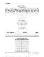
background image

190-00734-11 

May 2013  

Rev. 1 


Aircraft Make, Model, Registration Number, and Serial Number along with 
applicable STC Configuration information must be completed in Appendix A and 
saved as aircraft permanent records. 


GTX 330/33 with ADS-B Out  

System Maintenance Manual


Contains 

Instructions for Continued Airworthiness for STC SA01714WI


The document reference is online, please check the correspondence between the online documentation and the printed version.

Summary of Contents for GTX 330

Page 1: ... information must be completed in Appendix A and saved as aircraft permanent records GTX 330 33 with ADS B Out System Maintenance Manual Contains Instructions for Continued Airworthiness for STC SA01714WI The document reference is online please check the correspondence between the online documentation and the printed version ...

Page 2: ... and provided further that any unauthorized commercial distribution of this manual or any revision hereto is strictly prohibited Garmin International Inc 1200 E 151st Street Olathe KS 66062 USA Telephone 913 397 8200 www garmin com Garmin Europe Ltd Liberty House Bulls Copse Road Hounsdown Business Park Southampton SO40 9LR UK Phone 44 0 23 8052 4000 Fax 44 0 23 8052 4004 Garmin AT Inc 2345 Turner...

Page 3: ...ons are used to alert the individual that damage to equipment may results if the procedural step is not followed to the letter NOTE Notes are used to expand and explain the preceding step and provide further understanding of the reason for the particular operation WARNING This product its packaging and its components contain chemicals known to the State of California to cause cancer birth defects ...

Page 4: ... ADS B Out 190 00734 11 Maintenance Manual with ICA Rev 1 iv This page intentionally left blank The document reference is online please check the correspondence between the online documentation and the printed version ...

Page 5: ...ECTRICAL BONDING TEST 4 5 4 7 ADDITIONAL INSTRUCTIONS 4 6 5 TROUBLESHOOTING 5 1 5 1 GTX GENERAL TROUBLESHOOTING 5 1 5 2 GTX FAILURE ANNUNCIATIONS 5 2 5 3 CONNECTOR PINOUT INFORMATION 5 3 6 UNIT REMOVAL AND REINSTALLATION 6 1 6 1 GTX 330 330D 6 1 6 2 GTX 33 33D 6 3 6 3 TRANSPONDER ANTENNA 6 4 7 SOFTWARE 7 1 7 1 SOFTWARE CHECK 7 1 7 2 SOFTWARE UPDATE 7 2 7 3 SOFTWARE LOADING 7 2 8 SYSTEM CONFIGURATI...

Page 6: ...ENTATION 1 2 TABLE 2 GTN 7XX SERIES TRANSPONDER CONTROL REFERENCE DOCUMENTS 3 3 TABLE 3 GTN 6XX SERIES TRANSPONDER CONTROL REFERENCE DOCUMENTS 3 3 TABLE 4 MAINTENANCE INTERVALS 4 2 TABLE 5 GTX ELECTRICAL LOAD 4 6 TABLE 6 GTX ALL MODELS TRANSPONDER TROUBLESHOOTING 5 1 TABLE 7 GTX 330 330D TRANSPONDER FAILURE FAULT MESSAGES 5 2 TABLE 8 GTX 33 33D TRANSPONDER FAILURE FAULT MESSAGES 5 2 TABLE 9 CONNEC...

Page 7: ...ly tailored to maintenance practices Section 4 Instructions for Continued Airworthiness Provides maintenance instructions for continued airworthiness of the GTX 330 33 with ADS B Out Section 5 Troubleshooting Provides troubleshooting information to aid in diagnosing and resolving potential problems with the GTX 330 33 with ADS B Out systems Section 6 Unit Installation Removal Gives instructions fo...

Page 8: ...vel Garmin Dealers may obtain the latest revision of this document on the Garmin Dealer Resource Center website Owner operators may obtain the latest revision of this document from the www flyGarmin com Support page or by contacting a Garmin dealer contacting Garmin Product Support at 913 397 8200 toll free 866 739 5687 or using around the world contact information on www flyGarmin com A Garmin Se...

Page 9: ...em GPS Global Positioning System GTN Garmin Touchscreen Navigator GTX Garmin Transponder HSDB High Speed Data Bus ICA Instructions for Continued Airworthiness STC Supplemental Type Certificate TAS Traffic Advisory System TCAS Traffic Alert and Collision Avoidance System TIS Traffic Information Service TSO Technical Standard Order WAAS Wide Area Augmentation System The document reference is online ...

Page 10: ...ADS B Out 190 00734 11 Maintenance Manual with ICA Rev 1 1 4 This page intentionally left blank The document reference is online please check the correspondence between the online documentation and the printed version ...

Page 11: ...d timer functions depending on equipment connections and configuration selection The unit also features an altitude monitor TIS traffic advisories and flight timers A voice or tone audio output announces altitude deviation TIS traffic advisory and count down timer expiration Additionally the GTX 330 330D display will annunciate when the unit is actively transmitting ADS B information The GTX 330 3...

Page 12: ...hrough the GTN The Garmin GTX 33 33D transponder s communicates with the on side GTN 6XX 7XX through RS 232 digital interface This STC installation allows for installation of two GTX 33 non diversity transponders two GTX 33D Diversity transponders or one of each type Power is provided by the aircraft s existing Avionics Bus Each non diversity GTX 33 transponder interfaces with a transponder antenn...

Page 13: ...t Rev 1 Maintenance Manual with ICA 2 3 Figure 3 GTX 33 33D Transponder Figure 4 GTX 33 or GTX 33D Interface Summary The document reference is online please check the correspondence between the online documentation and the printed version ...

Page 14: ...ADS B Out 190 00734 11 Maintenance Manual with ICA Rev 1 2 4 This page intentionally left blank The document reference is online please check the correspondence between the online documentation and the printed version ...

Page 15: ...Mode A and Mode S In this mode the transponder replies to Mode A Mode C and Mode S interrogations as indicated by the Reply Symbol but the replies do not include altitude information ALT Selects Mode A Mode C and Mode S In ALT mode the transponder replies to identification altitude and Mode S interrogations as indicated by the Reply Symbol Replies to altitude interrogations include the standard pr...

Page 16: ...lds are displayed and enters the number nine into the Count Down timer Used in Configuration mode Code Selection Code selection is entered with eight keys 0 7 providing 4 096 active identification codes Pushing one of these keys begins the code selection sequence The new code is not activated until the fourth digit is entered Pressing the CLR key moves the cursor back to the previous digit Pressin...

Page 17: ...st mode is selected in Configuration mode Contrast is controlled by the 8 and 9 keys DISPLAY This page is only displayed if manual backlighting mode is selected in Configuration mode Backlighting is controlled by the 8 and 9 keys ADS B TX Controlled by START STOP key Starts stops extended squitter function FLIGHT ID If system is configured for FLT ID PWR UP ENTRY at installation the FLIGHT ID entr...

Page 18: ... 11 Maintenance Manual with ICA Rev 1 3 4 Figure 6 GTN 7XX Transponder Control Figure 7 GTN 6XX Transponder Control The document reference is online please check the correspondence between the online documentation and the printed version ...

Page 19: ...The document reference is online please check the correspondence between the online documentation and the printed version ...

Page 20: ...4 Replacement of GPS Position source s Cleaning The GTX 330 display and bezel may be cleaned periodically when required Cleaning can be accomplished using a soft cotton cloth dampened with clean water DO NOT use any chemical cleaning agents Care should be taken to avoid scratching the surface of the display N A On Condition Testing The GTX 330 33 transponders must be tested and shown to comply wit...

Page 21: ...ctual or Suspected Inspect the antenna and surrounding installation 4 5 On Condition The GTX 330 33 transponder receiver sensitivity must be tested and shown to comply with Title 14 CFR Part 43 Appendix F 8 4 On Condition The document reference is online please check the correspondence between the online documentation and the printed version ...

Page 22: ...st be replaced 4 Inspect any bonding straps for corrosion loose connections or signs of damage 5 Inspect the condition of the wiring harnesses and coaxial cables a Inspect all instrument panel wiring and coax for chafing damage proper routing of wire bundles and security of attachment in accordance with AC 43 13 1B Chapter 11 Section 8 Paragraph 11 96 Pay particular attention to possible areas of ...

Page 23: ...he Electrical bonding test specified in Section 4 6 Post Lightning Strike Inspection A post lightning strike inspection must be done for a suspected or actual lightning strike to antennas Inspect antenna and surrounding installation to ensure that there is no structural damage around the areas where lightning may have attached If there is visible sign of damage to the antenna then it should be rep...

Page 24: ...______ millivolts if installed Lower Transponder Antenna __________ millivolts if installed Ensure that at each test point no more than 5 millivolts 5 mΩ are present In this case voltage is equivalent to resistance Ω given that precisely 1 amp reference current is present TIP If 1 amp reference current cannot be maintained note the difference between the attainable current and 1 amp reference curr...

Page 25: ...ance Weak or intermittent radar contact reported by ATC Check and verify integrity of the antenna installation ground planes and coaxial cables Check for proper electrical bonding grounding of the antenna installation Test coaxial cables for insertion loss and VSWR Voltage Standing Wave Ratio VSWR should be checked with an in line type VSWR wattmeter inserted in the coaxial transmission line betwe...

Page 26: ...S B TX is selected to ON This option only available is ADS B TX is configured for PILOT SET Table 8 GTX 33 33D Transponder Failure Fault Messages Failure Message Cause Solution TRANSPONDER 1 ADSB is not transmitting position The transponder has insufficient data to support ADS B Out transmission Ensure the aircraft has a clear view of the sky Ensure GTN 6XX 7XX is powered and receiving valid GPS p...

Page 27: ...S addresses Verify the Mode S address for each transponder and verify that they match 5 3 CONNECTOR PINOUT INFORMATION Figure 9 Rear View Connector P3301 Table 9 Connector Pinout Pin GTX 33 33D Pin Name GTX 330 330D Pin Name I O 1 RESERVED AVIONICS MASTER ON SELECT In 2 ALTITUDE A1 ALTITUDE A1 In 3 ALTITUDE C2 ALTITUDE C2 In 4 ALTITUDE A2 ALTITUDE A2 In 5 ALTITUDE A4 ALTITUDE A4 In 6 ALTITUDE C4 A...

Page 28: ...29 ARINC 429 IN 3 B ARINC 429 IN 3 B In 30 ARINC 429 OUT 2 A ARINC 429 OUT 2 A Out 31 EXTERNAL SUPPRESSION I O EXTERNAL SUPPRESSION I O I O 32 ARINC 429 IN 1 A ARINC 429 IN 1 A In 33 ARINC 429 IN 2 A ARINC 429 IN 2 A In 34 ARINC 429 OUT 1 B ARINC 429 OUT 1 B Out 35 ARINC 429 IN 1 B ARINC 429 IN 1 B In 36 ARINC 429 IN 2 B ARINC 429 IN 2 B In 37 ARINC 429 OUT 1 A ARINC 429 OUT 1 A Out 38 RESERVED RE...

Page 29: ... SPARE 60 AIRCRAFT POWER 2 AIRCRAFT POWER 2 In 61 NOT USED SPARE 62 SWITCHED POWER OUT SWITCHED POWER OUT Out Denotes Active Low Ground to activate 5 3 1 POWER AND LIGHTING FUNCTION Table 10 Lighting Power Pin Assignments Pin Name Pin Number I O Unit 33 330 AIRCRAFT POWER 1 21 In Both AIRCRAFT POWER 1 42 In Both AIRCRAFT POWER 2 56 In Both AIRCRAFT POWER 2 60 In Both SWITCHED POWER OUT 62 Out Both...

Page 30: ...Pin Number I O Unit 33 330 ALTITUDE D4 11 In Both ALTITUDE A1 2 In Both ALTITUDE A2 4 In Both ALTITUDE A4 5 In Both ALTITUDE B1 7 In Both ALTITUDE B2 9 In Both ALTITUDE B4 10 In Both ALTITUDE C1 8 In Both ALTITUDE C2 3 In Both ALTITUDE C4 6 In Both ALTITUDE COMMON 50 Both 5 3 4 DISCRETE FUNCTIONS Discrete Outputs Table 13 Discrete Outputs Pin Name Pin Number I O Unit 33 330 ALTITUDE ALERT ANNUNCIA...

Page 31: ... 232 INPUT OUTPUT Table 15 RS 232 Connections Pin Name Pin Number I O Unit 33 330 RS 232 OUT 1 23 Out Both RS 232 IN 1 22 In Both RS 232 OUT 2 25 Out Both RS 232 IN 2 24 In Both 5 3 6 ARINC 429 INPUT OUTPUT Table 16 Arinc 429 Connections Pin Name Pin Number I O Unit 33 330 ARINC 429 OUT 1A 37 Out Both ARINC 429 OUT 1B 34 Out Both ARINC 429 IN 1A 32 In Both ARINC 429 IN 1B 35 In Both ARINC 429 IN 2...

Page 32: ...ADS B Out 190 00734 11 Maintenance Manual with ICA Rev 1 5 8 This page intentionally left blank The document reference is online please check the correspondence between the online documentation and the printed version ...

Page 33: ... hole at the bottom of the unit face 3 Rotate the hex tool clockwise while pressing on the left side of the bezel until the unit is firmly seated in the rack 4 Count the number of complete revolutions the Allen screw can be turned until it cannot turn any more Take care not to over tighten Three 3 turns is the minimum for proper installation If fewer than three 3 turns are possible ensure there ar...

Page 34: ...t 190 00734 11 Maintenance Manual with ICA Rev 1 6 2 Figure 10 GTX 330 Mounting Rack Connector Assembly The document reference is online please check the correspondence between the online documentation and the printed version ...

Page 35: ...tallation 1 Visually inspect the connectors to ensure there are no bent or damaged pins Repair any damage 2 Gently insert the GTX 33 33D into its rack The handle should engage the dogleg track 3 Press down on the GTX 33 33D handle to lock the unit into the rack 4 Lock the handle to the GTX 33 33D body using the Philips head screw Figure 11 GTX 33 Mounting Rack Connector Assembly The document refer...

Page 36: ...efer to A 2 for antenna location 2 Disconnect the antenna coaxial cable 3 Remove the hardware securing the antenna 4 Remove antenna Reinstallation 1 Install antenna using retained hardware 2 Connect the antenna coaxial cable 3 Test the GTX according to Section 8 4 The document reference is online please check the correspondence between the online documentation and the printed version ...

Page 37: ... or if the software is not successfully loaded DO NOT continue Troubleshoot and resolve the issue before continuing GTX 330 330D Software Version Check 1 Start the GTX 330 330D in normal mode 2 Observe the start up screen as shown below and verify the Software Version number matches the approved version listed in the AML Equipment List Doc 005 00734 05 Figure 12 GTX 330 Status Page GTX 33 33D Soft...

Page 38: ...aded from the Dealer Resource Center at www flyGarmin com For dual GTX installations the software loading procedures below must be carried out on each GTX The GTX 330 software can be updated in the Configuration mode as well as in Test mode Updating software in Configuration mode does not require the TEST MODE SELECT switch However for the GTX 33 series the TEST MODE SELECT switch is required See ...

Page 39: ...eived or not Failure to connect a dummy load or antenna during this procedure will cause the transponder to fail 1 Remove power from the GTX 2 Connect the test harness to the GTX and laptop as shown in Figure 14 3 Enable the TEST MODE switch on the test harness 4 Power on the GTX 5 Double click on the file UPLOADXX BAT XX is an incremental number assigned to a specific software version The program...

Page 40: ...ADS B Out 190 00734 11 Maintenance Manual with ICA Rev 1 7 4 This page intentionally left blank The document reference is online please check the correspondence between the online documentation and the printed version ...

Page 41: ...ompletion of any maintenance activities 8 3 1 GTX 330 330D CONFIGURATION Holding down the FUNC key and pressing the ON key provides access to the configuration pages The FUNC key sequences forward through the configuration pages The START STOP key reverses through the pages stopping at the Menu page The CRSR key highlights selectable fields on each page When a field is highlighted the 0 9 keys ent...

Page 42: ...ng a transponder ramp test set such as the IFR ATC 601A or TIC TR 220 S W v5 30 or later Specific instructions for operating the ramp tester are contained in the applicable operator s manual Reference Part 43 Appendix F for testing criteria The ramp test includes checks as follows 1 Reply Frequency 2 Suppression 3 Receiver Sensitivity 4 Reply RF Output Power 5 Mode S Diversity Channel Isolation if...

Page 43: ...turned to service Record the following information in appropriate aircraft maintenance logs Part number and version number of any software updates performed during maintenance Record part and serial numbers of any LRU which was replaced Any other applicable information related to the maintenance work performed on the aircraft The document reference is online please check the correspondence between...

Page 44: ...ADS B Out 190 00734 11 Maintenance Manual with ICA Rev 1 9 2 This page intentionally left blank The document reference is online please check the correspondence between the online documentation and the printed version ...

Page 45: ...NERAL INFORMATION Date ____ ____ ____ By ______________________________________ AIRCRAFT Make Model Serial Reg GTX 1 Unit Model Unit P N Mod Level Serial GTX 2 N A Unit Model Unit P N Mod Level Serial The document reference is online please check the correspondence between the online documentation and the printed version ...

Page 46: ...ed equipment Document all interfaced equipment model part number and installed locations in the following table Also sketch equipment locations and wire routing on the diagrams in A 5 or A 6 as appropriate LRU Installed Location F S Description of Location The document reference is online please check the correspondence between the online documentation and the printed version ...

Page 47: ...ved from aircraft Electrical Load A 1 Comment Subtotal Items added to aircraft Electrical Load A 1 Comment Subtotal Net Change in Bus Load 1 Use typical current draw when performing this calculation The document reference is online please check the correspondence between the online documentation and the printed version ...

Page 48: ... equipment that is interfaced to the GTX 330 33 GTX Port Numbers When applicable write in the GTX 330 33 port number or numbers used for the interface This column is generally applicable only to serial ports such as RS 232 and ARINC 429 Table 17 1 GTX 330 33 Interfaced Equipment 1 GTX 330 33 Equipment Type Model GTX 330 33 Port Number Audio Panel Display Encoding Altitude GPS 1 GPS 2 Heading Air D...

Page 49: ... 18 2 GTX 330 33 Interfaced Equipment 2 GTX 330 33 Equipment Type Model GTX 330 33 Port Number Audio Panel Display Encoding Altitude GPS 1 GPS 2 Heading Air Data The document reference is online please check the correspondence between the online documentation and the printed version ...

Page 50: ...INGLE ENGINE The following diagram depicts approximate location of all LRUs along with the wire routing for the GTX 330 33 throughout the aircraft structure for a single engine aircraft The document reference is online please check the correspondence between the online documentation and the printed version ...

Page 51: ... TWIN ENGINE The following diagram depicts approximate location of all LRUs along with the wire routing for the GTX 330 33 throughout the aircraft structure for a twin engine aircraft The document reference is online please check the correspondence between the online documentation and the printed version ...

Page 52: ...olume Message Altitude Monitor Count Down Timer Page Change Traffic Messages Display Mode Level BKLT KEY RSP Time RSP Time If MAN selected as BKLT source above the additional fields below must be configured If MAN Selected as KEY source above the additional fields below must be configured Level Level Min Min BKLT Source KEY Source Slope Slope Offset Offset Contrast Mode VFR Key Configuration Arinc...

Page 53: ... Port 1 Port 2 Transponder 2 Input Output Port 1 Port 2 Field Setting Field Setting VS Rate Format VFR ID Altitude Alert Deviation Squat Switch Temperature Sensor Installed Units Sense US Tail Delay Time 2 Hex Address Auto Flight Timer Mode S Flight ID GPS X Ofst GPS Y Ofst GPS Integrity 1E 7 Aircraft Type Max A S AC Length Type AC Width Type ADS B TX 1090 IN UAT IN EHS Gray Code The document refe...

Page 54: ...e following configuration Input GTX Mode S 1 or 2 for XPDR 2 if installed Output GTX Mode S 1 or 2 for XPDR 2 if installed Transponder 1 Input Output Baud Parity Port 1 9600 No Parity Port 2 9600 No Parity Transponder 2 Input Output Baud Parity Port 1 9600 No Parity Port 2 9600 No Parity Arinc 429 Configuration Transponder 1 Input Speed Output Speed Port 1 Port 2 Port 3 Port 4 Transponder 2 Input ...

Page 55: ...ced Surveillance Air Ground Logic Surveillance Integrity Level 1E 7 Squat Switch Sense Temperature Switch Installed Max Airspeed 1090 Input Address Type UAT Input Address GPS Antenna Longitudinal Offset Flight ID Type GPS Antenna Lateral Offset Audio Configuration All settings in this section will be the same for each installed transponder Field Setting Field Setting Altitude Monitor N A Has no ef...

Page 56: ...aft wiring diagrams showing the equipment installed by this STC or a markup of the interconnect diagrams from the STC installation manual detailing which equipment was installed and how it was connected The document reference is online please check the correspondence between the online documentation and the printed version ...

Reviews: