GXM
™
54
INSTALLATION
INSTRUCTIONS
Important Safety Information
WARNING
The weather information provided through this product is subject
to service interruptions and may contain errors, inaccuracies, or
outdated information, and consequently should not be relied
upon exclusively. Always use common sense while navigating,
and check alternate weather information sources prior to making
safety-related decisions. You acknowledge and agree that you
shall be solely responsible for use of the weather information
and all decisions taken with respect to navigating in weather.
Garmin
®
will not be responsible for any consequences of using
SiriusXM
®
weather information.
When connecting the power cable, do not remove the in-line
fuse holder. To prevent the possibility of injury or product
damage caused by fire or overheating, the appropriate fuse
must be in place as indicated in the product specifications. In
addition, connecting the power cable without the appropriate
fuse in place voids the product warranty.
CAUTION
Always wear safety goggles, ear protection, and a dust mask
when drilling, cutting, or sanding.
NOTICE
When drilling or cutting, always check what is on the opposite
side of the surface.
Software Update
You must update the Garmin chartplotter software when you
install this device.
If your chartplotter has Wi
‑
Fi
®
technology, you should update the
software using the ActiveCaptain
™
app on a compatible
Android
™
or Apple
®
device. If your chartplotter does not have
Wi
‑
Fi technology, you should update the software using a
memory card and a Windows
®
computer.
For more information, go to
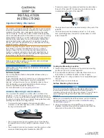
Antenna Mounting Considerations
You can mount the antenna on a flat surface or attach it to a
standard 1 in. OD, 14 threads per inch, pipe-threaded pole (not
included). You can route the cable outside of the pole or through
the pole. For best performance, consider these guidelines when
selecting the antenna mounting location.
• To ensure the best reception, the antenna should be
mounted in a location that has a clear, unobstructed view of
the sky in all directions .
• The antenna should not be mounted where it is shaded by
the superstructure of the boat , a radome antenna, or the
mast.
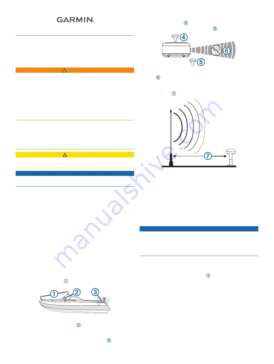
• The antenna should not be mounted near the engine or other
sources of Electromagnetic Interference (EMI) .
• If a radar is present, the antenna should be mounted above
the path of the radar . If necessary, the antenna may be
mounted below the path of the radar .
• The antenna should not be mounted directly in the path of the
radar .
• The antenna should be mounted at least 1 m (3 ft.) away
from (preferably above) the path of a radar beam or a VHF
radio antenna .
Testing the Mounting Location
1
Temporarily secure the antenna in the preferred mounting
location and test it for correct operation.
2
If you experience interference with other electronics, move
the antenna to a different location, and test it again.
3
Repeat steps 1–2 until you observe full or acceptable signal
strength.
4
Permanently mount the antenna.
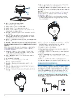
Surface Mounting the Antenna
NOTICE
If you are mounting the bracket on fiberglass with screws, it is
recommended to use a countersink bit to drill a clearance
counterbore through only the top gel-coat layer. This will help to
avoid cracking in the gel-coat layer when the screws are
tightened.
Before you permanently mount the antenna, you must test the
mounting location for correct operation (
).
1
Using the surface-mount bracket as your mounting
template, mark the three pilot-hole locations and trace the
cable-hole in the center of the bracket.
February 2019
190-02153-90_0A


