background image

MX20

TM

color Multi-Function Display 
pilot’s guide

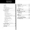
Summary of Contents for Mobile 20

Page 1: ...MX20TM color Multi Function Display pilot s guide ...

Page 2: ... other electronic storage medium to be viewed and to print one copy of this manual or of any revision hereto provided that such electronic or printed copy of this manual must contain the complete text of this copyright notice and provided further that any unauthorized commercial distribution of this manual or any revision hereto is strictly prohibited Information in this document is subject to cha...

Page 3: ...y 2003 4 1 560 1026 05a June 2003 5 0 560 1026 05 Rev B September 2003 5 0 5 1 560 1026 05 Rev C January 2004 5 2 560 1026 05 Rev D May 2004 5 3 560 1026 06 Rev November 2004 5 4 5 5 560 1026 07 Rev February 2005 5 5 560 1026 07 Rev A April 2005 5 6 560 1026 08 Rev A May 2005 5 6 560 1026 08 Rev B November 2005 5 7 560 1026 09 Rev A Ordering Information To receive additional copies of this MX20 Pi...

Page 4: ...NGEMENT IF YOU HAVE RECEIVED ANY WARRANTIES REGARDING THE MX20 OR THE SOFTWARE THOSE WARRANTIES DO NOT ORIGINATE FROM AND ARE NOT BINDING ON MS No Liability for Certain Damages EXCEPT AS PROHIBITED BY LAW MS SHALL HAVE NO LIABILITY FOR ANY INDIRECT SPECIAL CONSEQUENTIAL OR INCIDENTAL DAMAGES ARISING FROM OR IN CONNECTION WITH THE USE OR PERFORMANCE OF THE SOFTWARE THIS LIMITATION SHALL APPLY EVEN ...

Page 5: ...ion or their subsidiaries providing the Supplemental Components will be the licensor with respect to such S W THE SUPPLEMENTAL COMPONENTS AND ANY IF ANY SUPPORT SERVICES RELATED TO THE SUPPLEMENTAL COMPONENTS ARE PROVIDED AS IS AND WITH ALL FAULTS ALL OTHER DISCLAIMERS LIMITATION OF DAMAGES AND SPECIAL PROVISIONS PROVIDED BELOW AND OR OTHERWISE WITH THE SOFTWARE SHALL APPLY TO SUCH SUPPLEMENTAL CO...

Page 6: ...needs as they change in the future About This Manual This manual may be used as a summary a reference and a learning tool Information is provided about all of the functions available to the MX20 Your specific installation may not include all of these functions Take a few moments to familiarize yourself with the various sections in this manual The Getting Started sec tion gives an introduction to th...

Page 7: ...mencing the maneuver Uncoordinated deviations may place an aircraft in close proximity to other aircraft under ATC control not seen on the airborne equipment and may possibly result in the issuance of a pilot deviation The Terrain function shows you the general terrain elevations relative to your altitude and are advisory in nature Individual obstructions may be shown if available in the database ...

Page 8: ... Returning To Normal Condition 12 Alert Hot Key 13 Options Menu 13 Thumbnail Feature 13 Traffic on Thumbnail 14 Terrain on the Thumbnail 14 Obstructions on the Thumbnail 14 Thumbnail Activation 14 Traffic Information Services TIS 14 Message Log MSG 18 Custom Map MAP 19 Auto Zoom 19 Map Scale 19 Pan 20 Info 20 Info In Pan Mode 21 Initial Zoom Level 21 Custom Map Menu Option Page 1 21 Flight Plan 21 M...

Page 9: ...ld 39 Shield Heights 40 Shield Ranges 40 TCAD 9900BX Menu Options 40 Altitude Option Relative Pressure 40 Filter 40 Volume 40 Approach Mode 40 Ground Flight Mode 40 ADS B Traffic TRAF Function 41 Traffic Description 43 TIS B Traffic 44 TIS B Limitations 45 Degraded Target 46 Surface Targets 46 Target Color 46 Traffic Altitude Values 46 Ident GDL 90 UAT only 46 Confirm Code 47 Operation 47 Traffic Option...

Page 10: ...r Overlay Page 2 64 Label 64 Flight Plan 64 Legend 65 Map Detail 65 Map Orientation 65 Text Display 66 Selecting Text Data 66 Smart Key Function 67 Viewing Text TAFs 67 Sorting FIS Messages 68 Status Information 68 GDL 69 69A Flight Information Service FIS Function 69 Weather Product Zoom Scale 69 Temporary Flight Restrictions TFRs 70 NEXRAD Description 70 NEXRAD Abnormalities 70 NEXRAD Limitation...

Page 11: ...elect Chart 93 Select Loaded 93 Load Current 94 Airport Surface Charts 94 Viewing Surface Charts 94 Operational Considerations 95 When to Load a Chart 95 Flying an Approach 95 Approach to Surface Map Transitions 95 Chart NOTAMS 96 Important System Limitations 96 Invert Option 96 Typical Operational Scenario 97 Typical Taxi Scenario 97 Typical Takeoff Scenario 97 Typical Approach Scenario 97 Typica...

Page 12: ... 113 Altitude Units 113 GPS and Data Link Status 114 System Test Page 115 Test Pattern 1 115 Red Green Blue White Test Pattern 115 Caring For Your MX20 116 Display Care and Cleaning 116 Contacting the Factory 116 Troubleshooting 117 Garmin Data Cards 121 Installing and Removing Data Cards 121 Specifications 122 Physical Specifications 122 Power 122 Environmental 122 GDL 69 69A FIS Legends 123 Append...

Page 13: ...each function Press the FN key to show the available functions Press the smart key below the function label to go to the desired function While in each function press the MENU ENTER key to show the options for each function The options are shown on the right side of the display Press the MENU ITEM key to manipulate the options Some options toggle on off while some are tri state three choices MX20 ...

Page 14: ...ils about your flight plan and each waypoint The Terrain function shows a color coded map of terrain elevation in relation to your altitude The Flight Information Services FIS function when installed is capable of displaying text and graphic weather information with GDL 90 and GDL 69 69A installations The Lightning LT function when connected to the Goodrich WX500 Stormscope controls the overlay of ...

Page 15: ...en release to set the brightness automatically Function FN The Function keys are made up of one dedicated key on the lower left side of the display and the four smart keys to the right of it Press the function FN key repeatedly to scroll through the available functions The functions will appear above the smart function keys in turquoise Use the FN key to display a list of the main functions such a...

Page 16: ...a card The use of a data card allows you to easily update information Only change the data card when the power is turned off Handle your data card carefully Do not touch the connector edge of the data card To eject the card use a soft blunt object to press the data card ejector Gently pull the card straight out of the slot Insert a data card by pushing the card straight into the slot When fully in...

Page 17: ... shown below MX20s with a rotary Power Dimming knob will go into a pre heat mode for a short period of time on start up During the pre heat mode the display will remain dark The pre heat mode is designed to extend the life of the LCD backlight MX20 Power Dimming Graphic Display Menu Item Smart Keys Menu Enter Key Data Card Ejector Data Card Function Smart Keys Function Key Function Smart Key Label...

Page 18: ... 5 nm of your location This Traffic advisory is only available when the ADS B system with a UAT data link is installed and operational Refer to the TIS Traffic section for a description of TIS A and TIS B Skywatch TCAD TIS A Traffic The Traffic Advisory Alert will appear in amber on the left side of the display when the traffic sensor indicates an alerting condition Refer to the TIS Traffic section for ...

Page 19: ...ute flight plan is available from the exter nal navigation source Route flight plan information will not be shown on the maps No valid altitude information is available from the external source Altitude related functions will not operate such as terrain awareness No traffic information is received from the optional traffic sensor Traffic will not be displayed Your posi tion information may not be broad...

Page 20: ...nal external radar transmitter head Radar related functionality may not be available Green Indicates that the radar is ON and transmitting RF energy Appropriate precautions should be taken Green Flashing Indicates that the radar is in Hold and is transmitting RF energy Appropriate precautions should be taken Green Displayed when the GDL 90 is in Ident mode No valid datalink information is availabl...

Page 21: ...t the display brightness manually Manual brightness mode may be selected to adjust the display for difficult lighting conditions Push the knob in and the brightness is adjusted automatically according to the ambient light When the brightness is set automatically the display will not dim below a pre defined level Rocker Switch Model Press the and rocker switches at the same time briefly to set the bri...

Page 22: ...f any of the Self Tests fail red x contact your dealer or the factory Confirm Current Baro Correction A window may appear at startup and then every 30 minutes that displays the current barometric value You must verify the current value or enter a new value Press BARO to increase the value Press BARO to decrease the value Press OK to confirm the existing values or to accept changes you have just ente...

Page 23: ...ontrols for that function All of the described functions may not be available in each installation Function Description MSG Message Log Function MAP Custom Map Function IFR IFR En Route Map VFR VFR Sectional Map SPLIT Split Screen Displays Two Functions TRAF Traffic Display FPL Flight Plan Information TER Terrain Depiction FIS Flight Information Service Graphic and Text Weather XM XM Satellite Radi...

Page 24: ...oom and map mode will be restored This feature is designed to allow the pilot to establish a preferred cruise map setup and quickly view an advisory then return back to the previous setting For example Normal Cruise Condition Custom Map Function is being viewed at 5 nm in the ARC mode Terrain Advisory occurs at 10 nm in front of aircraft The Terrain Advisory Indicator flashes then goes steady on th...

Page 25: ...s have several pages of options The lower MENU ITEM key will allow you to reach the Next Page when multiple pages are available Press the MENU ENTER key a second time to remove the menu from view or wait a few seconds for the options to automatically extinguish Thumbnail Feature The Thumbnail feature provides a small map depiction that is overlaid in the upper left corner of the MX20 display It pr...

Page 26: ...be hidden from view The Thumbnail will not appear on the Traffic Func tion page if only traffic is presented in the Thumbnail Correspondingly it is not shown on the Terrain page if only terrain is presented in the Thumbnail This logic eliminates redundant views that would be created by the Thumbnail and normal views of traffic and terrain Additionally the Thumbnail is disabled while operating on the ...

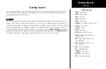
Page 27: ...15 Getting Started Function Summary ...

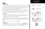
Page 28: ...16 Getting Started Function Summary ...

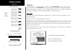
Page 29: ...17 Getting Started Function Summary ...

Page 30: ...ntil the message is viewed The MSG flag will remain in view while any messages remain in the message log New messages that have not been viewed will be highlighted as bold text 1 Press FN until you see the MSG function key 2 Press the MSG key 3 Use the UP DOWN arrow smart keys to move to additional messages if more than one page of messages exist 4 Press CLEAR to remove the stored messages Message ...

Page 31: ...vel to the far extremes of the zoom range When activated the indicated zoom level will change from a number to the text A followed by the zoom scale While in the Auto Zoom mode the screen will automatically adjust the current zoom level to maintain the current TO waypoint on the screen When approaching the waypoint the zoom level will not drop below 1 nm When the waypoint is reached and the next w...

Page 32: ...he viewed area back to your current position Info Press the INFO smart key to toggle viewing of information about the current TO waypoint Press the INFO key again to hide the information Each press of the key will step through the available information for the current destination waypoint The number of pages depends on the amount of information about the destination waypoint Press the Wx key to vi...

Page 33: ...tation Invert Nav Data and Load Chart The last option selection takes you to the next page of options The options have tri state choices that are also shown visually When the option is clear the icons and labels are not displayed When the option is solid icons and labels are all shown When the option box is partially filled only the icons are shown Flight Plan The Flight Plan option controls the di...

Page 34: ... corners waypoint bearing zoom and distance or full nav data The full nav data option includes the information in the four corners selection plus altitude barometer setting track and ground speed Altitude and barometer setting information is not shown in TAWS installations Load Chart Optional Once the airport is selected the individual approach chart to be overlaid can be loaded from a list of geo...

Page 35: ...ned VORs along with ILS and localizer approaches to be shown on the MX20 moving map This high level of integration is designed to provide additional simple to interpret situational awareness during high work load phases of flight The graphic display of Nav Comm information on the MX20 provides another source to help make sure you are using the intended navigational aid and your To From orientation ...

Page 36: ...is tuned on the SL30 the MX20 will display the currently tuned approach on the appropriate airport runway The SL30 Nav function provides an overall graphic view of the selected airport and approach based on runway extensions and the selected frequencies The standard ILS symbol is shown in magenta on the MX20 display Localizer Back Course Display The MX20 will draw the front course on its display w...

Page 37: ...e display of airspaces Pressing the MENU ITEM key next to Air space toggles between either the display of airspace boundaries and altitude information boundaries alone or no display of airspaces Airspaces defined as Class B C Alert Caution Danger Training Warning MOA Re stricted and Prohibited are depicted on the display Note that not all airspaces may be defined in the database as one of these airs...

Page 38: ... Airways toggles between either the display of the airway and label airway alone or no display of High Airways Water The Water option allows you to control the display of rivers and lakes Pressing the MENU ITEM key next to Waters toggles between either the display or no display of the bodies of water Roads The Roads option allows you to control the display of interstate and state highways Pressing...

Page 39: ...t is not being flown Terrain The Terrain option allows you select the display of topographical features Pressing the MENU ITEM key next to the Terrain option toggles between sectional absolute terrain awareness relative or no display of topographical features The sectional absolute display shows a display similar to a sectional map The terrain awareness absolute display shows a color coded view whe...

Page 40: ...or obstructions is North America only and are drawn only when the zoom level is below 50 nm Traffic The Traffic option turns the display of traffic information on or off ADS B Traffic information includes the location and identifier of a reporting aircraft its direction of travel elevation and the estimated path for the selected time interval See the section on the Traffic mode for more details on how t...

Page 41: ... if the MX20 receives strike data from an external source such as the WX500 Each reported lightning strike is shown as a red x on the display Strikes are not shown if the zoom level is below 20 nm Press the Next Page MENU ITEM key to display the next page of menu items Lightning strike icon red x Custom Map ...

Page 42: ...bels The last option selection takes you to the next page of options Flight Plan The Flight Plan option controls the display of the Flight Plan course line Pressing the MENU ITEM key next to the Flight Plan option toggles between showing and not showing the Flight Plan route line Map Orientation This option controls the screen orientation in reference to the aircraft symbol You may select from Nor...

Page 43: ...turned off only the symbol for waypoints along the flight plan will remain in view when the flight plan is enabled IFR Option Page 2 The second option page of the IFR Chart function lets you select options for the choices of Low Airways High Airways Airport Chart and Terrain The last option selection takes you back to the first page of options Low Airways The Low Airways option allows you to control ...

Page 44: ...e coverage of the chart A loaded chart is not being flown Load Chart Once the airport is selected the individual approach chart to be overlaid can be loaded from a list of geo ref erenced approach charts available for that airport Not all approach charts can be overlaid in this fashion and only geo referenced charts will be presented for selection from the Custom Map Because of this it is possible ...

Page 45: ...d not showing the Flight Plan route line Map Orientation This option controls the screen orientation in reference to the aircraft symbol You may select from North Up Track Up Track Up Arc Track Up 360 and Desired Track Up North Up sets magnetic north as the top of the screen Track Up sets the current track of the aircraft as the top of the screen Track Up Arc sets the current track of the aircraft...

Page 46: ...he corners waypoint bearing zoom and distance or full nav data The full nav data option includes the information in the four corners selection plus altitude barometer setting track and ground speed Label The LABEL key turns the labels over each item of information on or off When Labels are turned off only the symbol for waypoints along the flight plan will remain in view when the flight plan is enab...

Page 47: ...re the depicted terrain is a cross section of the terrain just below the aircraft s current track Obstructions are not shown on the profile display and the aircraft current altitude is provided next to the ownship symbol The altitude scale adjusts automatically with the aircraft altitude The zoom scale and map orientation are displayed in the upper right corner of the profile display When two functi...

Page 48: ...shown in heading mode meaning that track based flight plan information is not overlaid Traffic can also be shown on the Custom Map and in a small thumbnail view presented in the upper left corner of the screen Note that a heading input is required to display TAS traffic on the Custom Map Alert Hot Key Traffic alerts go one step further than the Advisory hot key feature and will automatically bring up ...

Page 49: ...considered other traffic Vert Smart Key TAS The Vertical Mode Vert smart key is used to select the vertical filtering mode for the TAS unit The following options are available and will allow traffic that is within the indicated range to be displayed ABV Above 9000 2700 NRM Normal 2700 2700 BLW Below 2700 9000 UNR Unrestricted No Limit Traffic Status Indicators Off Scale If a Traffic Alert target is not...

Page 50: ... bearing will be listed in text form below the ownship symbol TAS Menu Options Traffic Alert Mode Pop Up Prompt The Traffic Alert mode allows you to configure the currently selected Traffic Alert response If Pop Up is selected the Traffic function will automatically pop up when a Traffic Alert occurs If the Prompt mode is selected the Traffic Alert hot key prompt is shown when a Traffic Alert occurs If th...

Page 51: ...orner of the display as ALL no filtering or 2000 when the filtering is active Volume The volume of the TCAD voice alert can be adjusted by pressing the Volume button This opens a text menu where a value from 0 10 can be entered Approach Mode The Approach Mode sends the approximate elevation of the destination airport to the TCAD unit for Approach mode operations See the TCAD operator s manual for ad...

Page 52: ...re shown with a or while absolute altitudes are shown as just a number Filter An altitude filter allows targets that are outside of a 2000 vertical range to be filtered off the display The current mode is shown in the upper left corner of the display as ALL no filtering or 2000 when the filtering is active Volume The volume of the TCAD voice alert can be adjusted by pressing the Volume button This ope...

Page 53: ...t plan Traffic is shown in relation ship to your aircraft Smart keys allow you to zoom in and out show traffic labels and select an individual traffic target The Traffic function is not available in all software versions Review the Limitations section in the front of this guide for the limitations that apply traffic data ADS B Traffic ADS B Traffic page showing 360 degree arc ADS B Traffic information de...

Page 54: ...B ADS B equipment may be certified as an air to air system for enhancing situational awareness and as a surveil lance source for air traffic services Refer to the aircraft s flight manual supplement for the specific aircraft installation ADS B enables improved surveillance services both air to air and air to ground especially in areas where radar is ineffective due to terrain or where it is impractica...

Page 55: ...ot be used for avoidance maneuvers during IMC or other times when there is no visual contact with the other target aircraft ADS B is intended only to assist in visual acquisition of other aircraft No avoidance maneuvers are provided for nor authorized as a direct result of an ADS B target being displayed in the cockpit Use of ADS B surveillance services is limited to the service volume of the GBT ...

Page 56: ...adequate surveillance coverage from ground sensors and adequate broadcast coverage from Ground Based Transceivers GBTs The quality level of traffic information provided by TIS B is dependent upon the number and type of ground sensors available as TIS B sources and the timeliness of the reported data In order to receive TIS B services the following conditions must exist 1 The host aircraft must be e...

Page 57: ...r returns from the same aircraft When this happens the pilot will see duplicate traffic symbols i e TIS B shadows on the cockpit display c Updates of TIS B traffic reports will occur less often than ADS B traffic updates TIS B posi tion updates will occur approximately once every 3 13 seconds depending on the radar coverage In comparison the update rate for ADS B is nominally once per second d The TI...

Page 58: ...ely Surface Targets Surface vehicle targets in addition to ADS B targets are supported and are shown as tan rectangular ICONs They are displayed both on the Traffic Function page and on the Custom Map when traffic is turned on Target Color Service vehicle targets are colored in tan Aircraft targets are cyan in color Selected targets are green in color Traffic Altitude Values Altitudes shown next to t...

Page 59: ...it is sending an ident over the air 5 Press the SELECT key to consecutively select each Traffic item that is shown on the display When a target is selected additional information about that target is shown in the upper right corner of the display The selected target will be highlighted in green on the display Surface vehicle targets cannot be selected Information about the selected target includes ...

Page 60: ...options are controlled via the Traffic Function Menu and allow the pilot to toggle between Broadcast FID Broadcast VFR The MX20 must be configured as the UAT s control panel to make this function available Broadcast FID Causes the currently set Flight ID and permanently assigned ICAO address to be broadcast with the aircraft s current position The Flight ID and the ICAO address are shown on the lowe...

Page 61: ...elled by pressing the CANCEL smart key When a special service code is being transmitted the services label is illuminated To terminate the broadcast press the SERVICES option again Once terminated the code will revert back to the previously set code The MX20 must be configured as the UAT s control panel to make this function available Traffic Menu Option Page 2 The second menu option page of the Tra...

Page 62: ...t is above your altitude A indicates the target is below your altitude For instance if a value of 80 is shown the value means that the indicated traffic is 8000 feet above your altitude When Pressure Altitude is selected if a value of 121 is shown the value means that the indicated traffic is at 12 100 feet pressure altitude Pressure altitude does not show a or Remember that pressure altitude can be...

Page 63: ...on between target and ownship distance speed and altitude Position is noted in clock numerals as relative to direction of travel for each aircraft For instance a position noted as 10 1 means that the traffic is at your aircraft ownship 10 o clock position and your aircraft ownship is at the target s 1 o clock position Flight ID Editing The Enter Flight ID option allows you to edit your broadcasted ...

Page 64: ...al acquisition TIS A is there to assist you to visually acquire other aircraft around you and does not provide any information other than making you aware of other aircraft around you that the Mode S terminal radar can see This may not include all traffic around you Only transponder equipped aircraft that are visible to the terminal radar sensor will be broadcast to your aircraft Up to eight 8 targ...

Page 65: ...he traffic function by pressing the corresponding Smart key or continue to view the currently displayed function Traffic Alert Pop Up TA Popup When selected and viewing another function this feature will automatically display the traffic function screen when a Traffic Advisory TA alert is received from the TIS A sensor You may then view another function by pressing the FN key and selecting the desired...

Page 66: ...nsor has missed a radar sweep Target brightness is also reduced to indicate this condition TIS Unavailable to indicate the TIS A sensor is operating but outside of TIS A service coverage TIS Standby to indicate the TIS A sensor is in standby mode and not processing TIS A information even if it is available Traffic Off Scale noted in amber in the lower center of the display indicates that traffic has...

Page 67: ...current position in latitude and longitude ground speed and track In the lower right corner information for the current waypoint is displayed in the Waypoint Info box The Nearest Center frequency is shown just above the flight plan The Flight Plan function does not have any options Runway diagrams of airports will be displayed in the same orientation as the main map i e North Up Track Up or DTK Up ...

Page 68: ...ted or baro corrected just like the one in your aircraft s instrument panel The terrain screen has a 360 degree and a 120 degree display Both screens will show terrain relative to your position Colors used for terrain display are shown below NOTE The Terrain function shows you the general terrain elevations relative to your altitude and are advisory in nature Individual obstructions may be shown i...

Page 69: ...setting the barometric pressure Flight Plan The Flight Plan option controls the display of the Flight Plan course line Pressing the MENU ITEM key next to the Flight Plan option toggles between showing and not showing the Flight Plan route line TRK Up Arc TRK Up 360 This ring is marked in nautical miles from your airplane with the ring placed at one half the distance of the map scale For instance i...

Page 70: ...ternal TAWS based Terrain feature shows terrain as provided by an external TAWS sensor when con nected to and configured to receive that data from either the KGP 560 Landmark 8000 or KMH 820 When displaying external TAWS based terrain the external sensor determines the color coding and graphical presentation of terrain in the proximity of the aircraft See the Pilots Guide for the Honeywell KGP 560 ...

Page 71: ...eather data is received the airborne system will display that data for 20 minutes or until the power is cycled If no new data has been received for a given area the rainfall will be removed and the area will revert back to the cyan checkerboard pattern The FIS Function is based on a ground to air data link and requires that the appropriate ground systems are broadcasting weather data and the aircr...

Page 72: ...e screen 7 Press the arrow key to move to the FIS message time stamp in the farthest right column The smart key to the farthest right on the bottom of the screen will change to View Press View to expand the FIS Message window at the top of the screen A green arrow at the bottom of the FIS Message window indicates the more text is available Clearing Text FIS Messages While the FIS Category is highl...

Page 73: ...s when the data was assembled on the ground not the time the data was received by the FIS sensor For MX20s that have any GPS receiver that provides time the Zulu time is the time reported by the GPS receiver For MX20s that do not have time provided by a GPS receiver this field is invalid and dashed out Product times are shown in white when they are 0 to 5 minutes old gray when they are 5 to 10 minu...

Page 74: ...t assume that the same actual weather intensities are represented by the same colors The intensities as sociated with the color codes are available by viewing the Legend Overlay Option The legend associated with the weather radar image is shown for the depicted radar data US or Canadian Graphical WX Overlay Options A variety of graphical information is available with the Overlay function that is a...

Page 75: ...AIRMETs When enabled the following SIGMETs and AIRMETs are available for display SIGMETs are for Convective SIGMETs T AIRMET is for Surface Aloft Turbulence AIRMETs Z AIRMET is for Icing AIRMET S AIRMET is for an IFR condition such as a mountain obstruction Other is for other types of AIRMETs No Warn Area is to turn off all SIGMETs and AIRMETs These are collectively known as Warning Boxes and are ...

Page 76: ... technology both data types cannot be displayed at the same time When subscribed to both weather radar products you can alternate between the two with the Overlay option Menu Options for Overlay Page 2 1 Press the OVRL function key to allow selection of the Overlay choices when viewing the Graphical WX option 2 Press MENU ENTER to display menu items for the Overlay 3 Press MAIN MENU to return to t...

Page 77: ...adar data the following legends will appear Only the lower portion of the legend changes for Canadian radar data Map Detail Press MENU ENTER key and then press the Map Detail Menu Item key to choose between the display of No Overlays the Base Map or Map and Nav Aids Map Orientation Press MENU ENTER key and then press the Map Orientation Menu Item key to choose the configuration of the map orientati...

Page 78: ...t messages The columns are loosely defined as message type location and time stamp to handle the most common type of FIS up link data The different message types and data content are fully controlled by the ground broadcast systems The air borne system will automatically display any message type that is received US and Canadian text METARs text and graphical TAFs are available at the same time when...

Page 79: ...he data link When the Selection Pointer is in the center most column the fourth smart key displays the label Sort See below for how the sort option works When the Selection Pointer is in the right most column the fourth smart key displays the label View When pressed the currently viewed message is presented in a full screen mode This feature provides a mechanism to view large textual messages that...

Page 80: ...s based on distances from current ownship to a given airport the system must be able to correlate a Jeppesen airport that matches the location field of the received message If this lookup is successful a distance shall be presented adjacent to the location text If no corresponding location can be determined no distance is as signed but the message is presented at the end of the list The default sor...

Page 81: ... function key when displayed 2 The first two function smart keys at the bottom of the screen zoom IN and OUT on the map 3 The PAN key brings up the movement menu item keys at the right of the screen that allow you to move the view of the map 4 The fourth function smart key on the right will step through the four sub functions of GDL 69 69A FIS Current Forecast Text and Status 5 The Menu Enter key b...

Page 82: ...re possible abnormalities regarding displayed NEXRAD images Some but not all causes of abnormal displayed information include Ground Clutter Strobes and spurious radar data Sun strobes when the radar antenna points directly at the sun Military aircraft deploy metallic dust which can cause alterations in radar scans Interference from buildings or mountains which may cause shadows NEXRAD Limitations...

Page 83: ...y when displayed 2 Press the fourth function smart key on the right to select the Current Crnt sub function 3 The Menu Enter key brings up menu items for more detail on each sub function NEXRAD When enabled NEXRAD weather information is shown Composite data from all of the NEXRAD radar sites in the United States is shown This data is composed of the maximum reflectivity from the individual radar sw...

Page 84: ...the selected services 2 Press Done to turn the Legends off Lightning When enabled lightning strikes and cells are shown Lightning information indicates the location of cloud to ground lightning strikes The update rate is every five minutes Cell Movement When enabled Cell Movement shows the storm cells identified by the ground based system The movement is depicted by an arrow The tip of the arrow rep...

Page 85: ...n and direction the highest radar echo This is typically associated with storms This may not indicate the top of a storm or clouds only the highest radar return echo The information is derived from NEXRAD information and indicates the highest altitude at which precipitation is falling Refer to the Legend for a description of the Echo Tops coding The update rate is every 7 5 minutes Note Cloud Tops...

Page 86: ...own at a given altitude the data for that altitude has not been received Wait for the next update The update rate is every 12 minutes TFR Lbl Press MENU ENTER key and then press the TFR Lbl Menu Item key to toggle the TFR Identifier Labels on and off The TFR Identifier Labels note the TFR number and upper altitude near the TFR outline Label Press MENU ENTER key and then press the LABEL Menu Item key...

Page 87: ...or NEXRAD radar Coverage for active NEXRAD radar coverage areas METAR Echo Tops Cloud Tops Light ning and Winds Aloft Times are Zulu times when the data was assembled on the ground not the time the data was received or displayed by the FIS sensor Product times are shown in white when they are initially shown and change to blue and then yellow as they pass certain age thresholds A product time agin...

Page 88: ... 8 13 METAR 15 75 Echo Tops 10 5 18 Winds Aloft 15 75 AIRMET 15 51 SIGMET 15 51 Cyclone 15 51 County Warnings 8 23 Freezing Level 15 75 City Forecasts 15 51 TAF 15 75 Cloud Tops 10 5 18 Map Orientation Press MENU ENTER key and then press the Map Orientation Menu Item key to choose the configuration of the map orientation of DTK Up North Up TRK Up TRK Up Arc or TRK Up 360 GDL 69 69A FIS ...

Page 89: ...ities Forecasts are available for intervals of 12 24 36 and 48 hours This menu item key enables or disables this product Use the menu item key below the City key to select the current or forecast time The update rate is every 12 minutes Forecast Time The forecast time range can be selected to cover the current conditions 12 hours 24 hours 36 hours or 48 hours Each press of the forecast time menu i...

Page 90: ...Surface winds Refer to the Legend for a description of the color coding 1 Press the or arrow keys to display the legends for the selected services 2 Press Done to turn the Legends off Freezing Levels This product is not available at this time County The County selection provides specific public awareness and protection weather warnings for Hurricanes Tor nados Severe Thunderstorms Floods Flash Floo...

Page 91: ...to display the legends describing the graphic display colors Press the or arrow keys to display the legends for the selected services Press Done to turn the Legends off A graphic of each product legend is shown on page 75 Map Detail Press MENU ENTER key and then press the Map Detail Menu Item key to choose between the display of No Overlays the Base Map or Map and Nav Aids Map Orientation Press ME...

Page 92: ...art keys to move up or down the FIS category list The selected category is highlighted 2 Press the arrow key to move the items in the list for that category 3 While in the list for a category press the or function smart keys to highlight a particular message for the selected category The text for the selected message is shown in the FIS Message window in the upper portion of the screen 4 Press the...

Page 93: ... Category window 4 Press the or function smart keys to move up or down the FIS category list to highlight TFR 5 Press the arrow key to move the items in the list for the TFR category 6 While in the list for the TFR category press the or function smart keys to highlight a particular message for the selected category The text for the selected message is shown in the FIS Message window in the upper p...

Page 94: ...gle to the Diagnostics display The Diagnostics page information is displayed 3 Press the Start Diag menu item key to activate GDL 69 69A diagnostics Note After diagnostics have been run power to the GDL 69 69A must be recycled to return to proper operation for GDL 69 69A software versions prior to version 2 13 Activation The Activation page shows the radio identification numbers for one or both rec...

Page 95: ...o this instruction sheet and printed on a label on the back of the unit The IDs can also be retrieved through the MX20 in the Activation page of the Status sub function Contact your dealer if you are unable to locate the radio hardware IDs XM Satellite Radio Activation Weather and or audio data from your GDL 69 69A are provided by XM Satellite Radio a company separate and independent from Garmin C...

Page 96: ...e cycle Lightning Menu Option Page 1 The first option page of the Lightning function lets you select options for the choices of Flight Plan Display view Lightning groups Heading Stabilization and Stormscope System Data info The last option selection Next Page takes you to the next page of options Flight Plan The Flight Plan option controls the display of the Flight Plan course line Pressing the MEN...

Page 97: ...key to display the next page of menu items Lightning Menu Option Page 2 The second option page of the Lightning function lets you select options for the choices of Demo Self Test for the Stormscope Noise Monitor and Strike Test The last option selection takes you back to the first page of options Demo The Demo option places the WX500 sensor in a demonstration mode that simulates lightning strikes S...

Page 98: ...Strike Test The Strike Test feature is a function of the WX500 For details about using this feature refer to the WX500 owner s documents The Strike Test feature is used by installers to verify proper operation of the WX500 Test strikes are sent to the antenna The received test strike is then visually presented on the screen Antenna Change Message When an Antenna Change message is shown the lightni...

Page 99: ...mic overlay on the Custom IFR Map or as a static page through the dedicated Chart View Function Chart on the function menu When viewed as a dynamic overlay on the Custom IFR Map the chart will be properly geo referenced with respect to the base map Orientation track up north up etc zoom scale and aircraft position will all be properly presented relative to the chart data using the standard map con...

Page 100: ...ad of the entire contents of the Jeppesen CD ROM This process is performed using the data loader software tool provided by Jeppesen The MX20 Chart View data card can hold approximately 10 000 charts at a given time Chart Geo Referencing For the ownship position to be overlaid on the chart as viewed from the Custom IFR Map the chart must be available in a Geo Referenced version as supplied by Jeppe...

Page 101: ...The first airport within the list is the final destination waypoint as selected on the external GPS navigator with additional airports listed based on a nearest to present position search Airports and approach charts that are not geo referenced will not be shown for selection on this menu NOTE Prior to loading an approach chart there is an operational benefit to selecting the desired airport on the G...

Page 102: ...3 Highlight the desired airport with the arrow smart keys and then press the SELECT smart key 4 Highlight the desired approach with the arrow smart keys and then press the LOAD smart key 5 Adjust the zoom level using the IN or OUT smart keys Viewing the Chart as an Overlay Display of Coverage Area Once the desired approach chart has been loaded a green Annunciator bar with the approach name is ill...

Page 103: ...mode This limit does not apply when the auto zoom mode is tied to the GNS 480 series GPS receiver Chart Panning Panning on the loaded chart is currently not supported Entering the panning mode will disable the display of the chart and allow the underlying map layers to be presented Chart Orientation When the chart overlay is presented the orientation is identical to the currently selected orientat...

Page 104: ...m IFR map as described in previous sections All charts within the database geo referenced or not can be statically viewed from the Chart View Function Only geo referenced charts can be loaded for map overlay purposes The Chart View Function will retain the last view set and will not change the chart zoom level or pan setting when the function is exited and re entered allowing it to operate similar...

Page 105: ...thod allows the airport to be quickly located based on the current flight plan on the external GPS navigator Once the airport is located the Select Chart menu is presented see below allowing a specific chart for that airport to be either loaded or simply viewed Select Chart The Select Chart operation allows the list of charts for the currently selected airport to be listed in a pop up list Within th...

Page 106: ...peration the above conditions are met when the unit is turned on meaning that the airport surface map is displayed as soon as GPS position is acquired Note that the Zoom Scale Auto Transition feature deter mines the initial zoom scale that is set when the aircraft is on the ground which is important when working with surface charts Viewing Surface Charts The airport surface charts are treated simi...

Page 107: ...is above the air ground speed threshold The approach will be automatically unloaded when the aircraft s speed goes below the air ground speed threshold Flying an Approach It is important to recognize that the charts function is not intended to provide guidance information for flying an approach Its intended function is to provide basic situational awareness as to your current position relative to t...

Page 108: ...e maps does not occur and the approach is not automatically un loaded See the Initial Zoom and Transition Speed selection in the System Function Chart NOTAMS Any applicable NOTAMS that apply for a given chart are shown under the INFO key when that chart is selected The chart should be viewed for NOTAMS before use Important System Limitations Note that while on the ground and viewing airport surfac...

Page 109: ...ustom IFR Map will present the destination airport in the selection list Selecting this airport will then bring up the approach charts that are available for that airport which can then be loaded by pressing the LOAD smart key Typical Landing Scenario With an approach chart being flown upon touchdown and rollout the chart will be unloaded and the map will automatically switch to the airport surface...

Page 110: ...100 The ART2100 must be configured to emulate the ART2000 As a result only the ART2000 functions are available with the ART2100 The MX20 operates as both a display and radar control head allowing direct replacement of older display sys tems The modes and features supported by the MX20 for each of the radar heads are detailed in the following table Review the Limitations section in the front of this...

Page 111: ... head is powered up but is not transmitting Placing the unit into standby mode initiates the warm up sequence that is required by the transmitter within the radar head assembly Press ing the STBY ON key while in Standby mode turns on the radar in the Weather Mode While in the ON mode in both Map and Weather modes the green RDR annunciator is on solid indicating that the radar is energized and tran...

Page 112: ... Black Black Cyan Cyan Yellow Green Magenta Yellow Blue Magenta While in the Map mode the gain can be adjusted with the Gain and Gain keys see below Horizontal Mode The Horizontal Mode HORIZ commands the radar head to scan in the horizontal plane at a pilot selectable tilt angle In this mode the current Tilt angle is shown on the lower half of the display in green Vertical Mode GWX 68 and ART2000 ...

Page 113: ...djust the current bearing angle of the radar head when vertical sweeping is being performed While in the Vertical mode the bearing is adjusted using the BRG and BRG keys Values shown in the table below are in degrees from straight ahead Unit GWX 68 ART2000 2100 RS 181A Bearing 45L 45R 45L 45R NA Gain Control Available in MAP mode with the GWX 68 ART2000 and RS 181A and also in WX mode with the GWX...

Page 114: ...rest Once selected changing the scan mode to vertical will automatically set the bear ing of the vertical sweeps to the bearing previously indicated by the cursor line Conversely if vertical scanning is occurring a cursor line can be activated to pre select a specific tilt to a weather cell of interest Once selected changing the scan mode to horizontal will automatically set the tilt angle of the h...

Page 115: ... off When Stabilization is On a command is sent to the radar head instructing it to use the supplied gyro commands to compensate the sweep patterns for pitch and roll of the aircraft When stabilization is activated the STAB label will be green When Stabilization is turned off the STAB label is white Additional status infor mation is also shown while the radar menu is active Radar Troubleshooting F...

Page 116: ...t use the radar until its temperature falls and the fault clears XMITTER A problem is detected in the re ceiver or transmitter The unit may be hazardous to use Power off the radar The radar needs service CALIBRATE A problem has been detected with the internal factory calibration settings Power off the radar The radar needs service CONFIG The configuration settings are cor rupted or missing Power of...

Page 117: ...e FN key and then the XM function key when displayed 2 The function smart keys at the bottom of the screen let you control the Volume Vol Channel Chan Category Cat or select the channel directly by entering the number Direct 3 The Menu Enter key brings up menu items for more detail on each sub function Menu Page 1 The first option page of the XM Radio function lets you select the options for viewin...

Page 118: ...e key to reach the Main Menu page 3 Press the or arrow function smart keys to select the desired preset number 4 Press the Menu Enter key to save the channel into the selected preset number Last Channel The Last Channel menu item allows you to return to the last tuned channel if the MX20 has been off and then turned back on 1 In the XM radio function press the Menu Enter key 2 Press the Last Chann...

Page 119: ...s the or menu item smart keys to increase or decrease the audio volume Mute 1 In the XM radio function press the Vol function smart key on the bottom of the display 2 Press the Mute menu item key to mute or un mute the audio Note that the volume is muted when the GDL 69A is turned on Channels The Channel feature is used to navigate through the channels in the selected category 1 In the XM radio fu...

Page 120: ...all categories 4 Press the Menu Enter key to select the highlighted category 5 You can now use the Channel function to select a channel from the category list selected Direct Access Channels can be accessed directly by entering the channel number using the smart keys 1 In XM mode press the Direct function smart key The number values will be shown above the function and to the left of the menu item...

Page 121: ... to receive a strong enough XM signal to decode it Loading Acquiring channel audio or information Either the corresponding audio or text is temporarily unavailable for a given channel selected because the radio still has to receive and decode this information Off Air Channel not in service A valid XM channel number and its corresponding service ID is not broadcasting any programming or Channel Cha...

Page 122: ...hese IDs serve as identification codes for your XM equipped GDL 69 69A and are needed in the activation process The ID s is attached to this instruction sheet and printed on a label on the back of the unit The IDs can also be retrieved through the MX20 in the Radio ID page of the XM Satellite Radio function Contact your dealer if you are unable to locate the radio hardware IDs Contact XM Satellite ...

Page 123: ...seconds decimals DD MM SS SS or degrees minutes minutes decimals DD MM MM Set Baro Correction Units Baro Correction QNH can now be entered in Millibars in addition to Hg This preference is set under the SYS function Set Baro Correction You may enter the corrected barometric pressure so that the proper pressure altitude will be displayed 1 Press the MENU ITEM key for Set Baro Correction 2 The Funct...

Page 124: ...d is based on GPS ground speed The Auto Transition feature allows for optimal close in viewing while on the ground and optimal long range viewing while in flight without the user having to make manual zoom scale adjustments while in the takeoff and landing phases of flight The Zoom scale is shown in the lower left corner of the display The En Route and Ground zoom scales and the transition point are...

Page 125: ... disabled when the MX20 is connected to a GPS navigator other than an GNS 480 series navigator It allows the GNS 480 series equipment to instruct the MX20 to load a selected approach chart Display ICAO for US Airports Press the Menu Item key to toggle on off the display of ICAOs for US airports When enabled the leading K character for United States airports is displayed according to the ICAO forma...

Page 126: ...ls for both the internal GPS engine and the data link status When the MX20 is connected to a GDL 90 UAT only the ADS B Data Link Status line is present because there is no differentiation between ADS B and TIS B target data GPS satellite usage and signal strength are presented in the upper right of the info page in addition to each satellite s position in the sky If no GPS is installed in the MX20...

Page 127: ...ors to test the MX20 display Use this option to verify proper operation of the display or when contacting Customer Service Red Green Blue White Test Pattern Choosing the Red Green Blue or White options floods the screen with the selected color Use this option to verify proper operation of the display or when contacting Garmin Customer Service System System Test Page Menu Items System Test Test Patt...

Page 128: ...he area to condense moisture on the display and then wipe the area with the clean fabric Moisten a clean fabric with a small amount of water and wipe the display area Apply a small amount of glass cleaner without ammonia to the fabric and wipe the area Apply a small amount of isopropyl alcohol and wipe the area this is your last resort Contacting the Factory If efforts to resolve the problem fail ...

Page 129: ...e preceding section Be sure to have the information from the System Info page and the data card available before you contact your dealer or the factory Problem Possible Cause Action Unit does not power on or blank screen Wiring problem Improper brightness setting Low temperature Data card Check for proper wiring and con nections Check the fuse circuit breaker Check the display brightness setting A...

Page 130: ...er installer check for proper MX20 setup RTE Route flag Position source route Ensure that the external position source has an active route engaged ALT Altitude flag Serial altitude source Ensure the serial altitude encoder is powered up and working properly Have dealer installer check for proper installation and setup of the encoder If altitude data is provided by an Apollo GX product ensure that th...

Page 131: ...nents for proper operation Have dealer installer check for proper MX20 setup Special Terrain message Capstone General Aviation setup This is normal for the Capstone installation Have dealer installer check for proper MX20 setup TCAD flag TCAD Installation Ensure that the TCAD unit is installed and functional SKYW flag Skywatch Installation Ensure that the Skywatch unit is installed and functional RD...

Page 132: ...ing an invalid position Note that ADS B broadcasts do not include position reports when this flag is present Ensure the GDL 90 is installed and functional Ensure the GDL 90 GPS antenna has a clear view of the sky to receive GPS signals IDENT green flag This is not a problem This flag appears when the GDL 90 is in the Ident mode None required See the Installation Manual for additional troubleshooting ...

Page 133: ...the card The handle is still exposed when it is properly inserted DO NOT insert or remove the data card while the unit is powered on If you insert a data card and get a card format not recognized message try removing the card and reinserting it If the card is still not recognized contact Garmin Customer Service or your Garmin dealer for assistance Data cards are not waterproof should not be expose...

Page 134: ...r display with backlight ing 640 x 480 pixels Power 14 VDC MX20 2 0A 3 0A Max MX20 w Heater 3 0A 4 0A Max MX20 I O 2 5A 3 5A Max MX20 I O w Heater 3 5A 4 5A Max 28 VDC MX20 1 0A 1 5A Max MX20 w Heater 1 5A 2 0A Max MX20 I O 1 25A 1 75A Max MX20 I O w Heater 1 75A 2 25A Max Environmental Temp Range 4 F to 131 F 20 C to 55 C operating range Humidity 95 at 55 C Altitude 35 000 feet continuous Specifi...

Page 135: ...City Forecast Legend County Warnings Legend Freezing Levels Legend NEXRAD Legend METAR Legend Cloud Tops Legend Echo Tops Legend GDL 69 69A FIS Legends The following legends describe the graphical information on the GDL 69 69A FIS displays Winds Aloft Legend ...

Page 136: ...cho Tops XM FIS METARs XM FIS Winds Aloft XM FIS with NEXRAD Weather and Legend XM FIS Radar Coverage XM FIS City Forecast Sample GDL 69 69A FIS Displays The following displays provide examples of information shown in the GDL 69 69A FIS function ...

Page 137: ...f glass cleaner without ammonia to the fabric and wipe the area Apply a small amount of isopropyl alcohol and wipe the area this is your last resort To resolve problems that cannot be remedied using this guide contact Garmin Product Support in the U S A at 800 800 1020 or Garmin Europe at 44 1794 519944 Display Backlight The display backlight is rated by the manufacturer as having a usable life of...

Page 138: ...s that a radar sweep was missed and displayed data is not the latest Course The direction from your starting location to a destination Decluttering Reduction in displayed elements on the moving map at higher zoom scales Distance Destination The great circle distance from current location to a Go To destination or the final waypoint in a route Distance Next The great circle distance from current loc...

Page 139: ...Speed Display rate of travel in miles kilometers nautical miles per hour Time The time for the selected time zone Track The direction of movement relative to a ground position Also referred to as ground track Waypoint Destination The final waypoint in the route or the destination waypoint Waypoint Next The next waypoint in the route Glossary ...

Page 140: ...eflectivity DIS DIST Distance DTK Desired Track EMI Electromagnetic Interference ENR En Route ETP Echo Tops EULA End User License Agreement F Degrees Fahrenheit FID Flight Identification FIS Flight Information System FISDL Flight Information System Data Link FN Function FP FPL Flight Plan ft Feet GBT Ground Based Transceiver GM Greenwich Mean Time GND Ground GPS Global Positioning System GS Ground S...

Page 141: ...en NRM Normal OBS Omnibearing Selector OS Off Scale OVRL Overlay POS Position RD RDR RADAR RTE Route SCTR Sector SIDS Standard Instrument Departures SIGMET Significant Meteorological Information SKYW Skywatch STAB Stabilization STARS Standard Terminal Arrival Route STBY Standby SYS System TAF Terminal Aerodrome Forecast TAS Traffic Advisory System TAWS Terrain Awareness and Warning System TCAD Traffi...

Page 142: ...dix Abbreviations TRK Track also Ground Track UAT Universal Access Transceiver UNR Unrestricted VFR Visual Flight Rules VOL Volume VOR VHF Omnidirectional Radio Range WB Warning Boxes WX Weather XPDR Transponder ...

Page 143: ...export the Software to any country in violation of the export control laws of the United States of America Product Registration and Support Help us better support you by completing your online registration today Have the serial number of your MX20 handy and connect to the Garmin Web site www garmin com Look for the Product Registration link on the home page Also be sure to record your serial numbe...

Page 144: ...M DEFECTS IN THE PRODUCT Some states do not allow the exclusion of incidental or consequential damages so the above limitations may not apply to you Garmin retains the exclusive right to repair or replace the unit or software or offer a full refund of the purchase price at its sole discretion SUCH REMEDY SHALL BE YOUR SOLE AND EXCLUSIVE REMEDY FOR ANY BREACH OF WARRANTY To obtain warranty service ...

Page 145: ...00 East 151st Street Olathe KS 66062 3426 USA Phone 913 397 8200 FAX 913 397 8282 http www garmin com Be prepared to offer the following information about the installation Installation configuration list of any accessories Model number part number with mod levels and serial number Software Versions Description of problem Efforts made to isolate the problem Contacting the Factory ...

Page 146: ...8 Broadcast VFR 48 C Calibrate 104 Canadian radar 61 Canadian weather 62 64 66 Cards 121 Care Information 125 Categories 80 CDTI 44 Cell 85 Cell Movement 69 72 Chart View 2 22 87 91 92 Airport surface 94 Approach chart 90 AutoLoad 113 Chart overlay 89 Considerations 95 Data source 88 Geo referencing 88 Menu items 93 Overlay 90 Check antenna 109 City 77 City forecast 69 Cleaning 125 Clear 60 Cloud ...

Page 147: ...sary of Terms 126 127 GNS 480 19 32 87 113 GPS 114 Graphical Weather 59 62 Ground Flight Mode 40 Ground Zoom 112 GTX 330 28 52 53 GWX 68 98 Gyro 103 H HB 114 Heater 9 High airways 26 31 Hold 102 Horizontal Mode 100 101 Hurricanes 78 Hurricane track 69 HV 104 I ICAO address 48 113 Icing 78 Ident 8 46 120 IFR 30 78 IFR chart 2 IHAS 36 ILS 23 24 Info 20 21 91 114 Initial Zoom level 21 112 Intersectio...

Page 148: ...ge control 101 Radar return signals 103 Radar setup 103 Radar stabilization 103 Radar test 99 Radar troubleshooting 103 Radio ID 82 105 Rainfall 59 Ram 104 Range ring 50 RDR 8 119 Receiver performance 81 Reflectivity 71 Registration 131 Relative 27 Relative altitude 43 50 52 Roads 26 Rocker switch 9 Rotary knob 9 Route 7 RS 181 98 RTE 7 118 Runway 20 S Save Preset 106 Search 93 Search ID 93 Select ...

Page 149: ...2 TIS A 1 8 14 52 TIS B 14 44 Tornados 78 Towers 28 Track up 21 30 33 57 Track up 360 21 30 33 57 Track up arc 21 30 33 57 TRAF 7 Traffic 2 6 14 28 36 41 44 52 Advisory 53 Label 51 Status 37 Traffic Alert 13 38 53 Traffic Map Orientation 50 Traffic not displayed 38 Traffic off scale 54 Transition speed 112 Transmit Altitude 48 Transmit status 48 Transponder 43 44 Transponder code 49 Troubleshooting 103...

Page 150: ...138 Index Weather 69 XPDR 8 120 Z Zoom 13 19 22 30 31 33 34 35 36 37 41 47 56 69 87 90 91 92 93 94 95 96 112 113 Zoom level 12 19 21 28 29 69 Z AIRMET 63 ...

Page 151: ......

Page 152: ...151st Street Olathe Kansas 66062 U S A Garmin Europe Ltd Unit 5 The Quadrangle Abbey Park Industrial Estate Romsey SO51 9DL U K Garmin Corporation No 68 Jangshu 2nd Road Shijr Taipei County Taiwan www garmin com Garmin AT P N 560 1026 09 Rev A Garmin P N 190 00479 00 Rev D ...

Reviews: