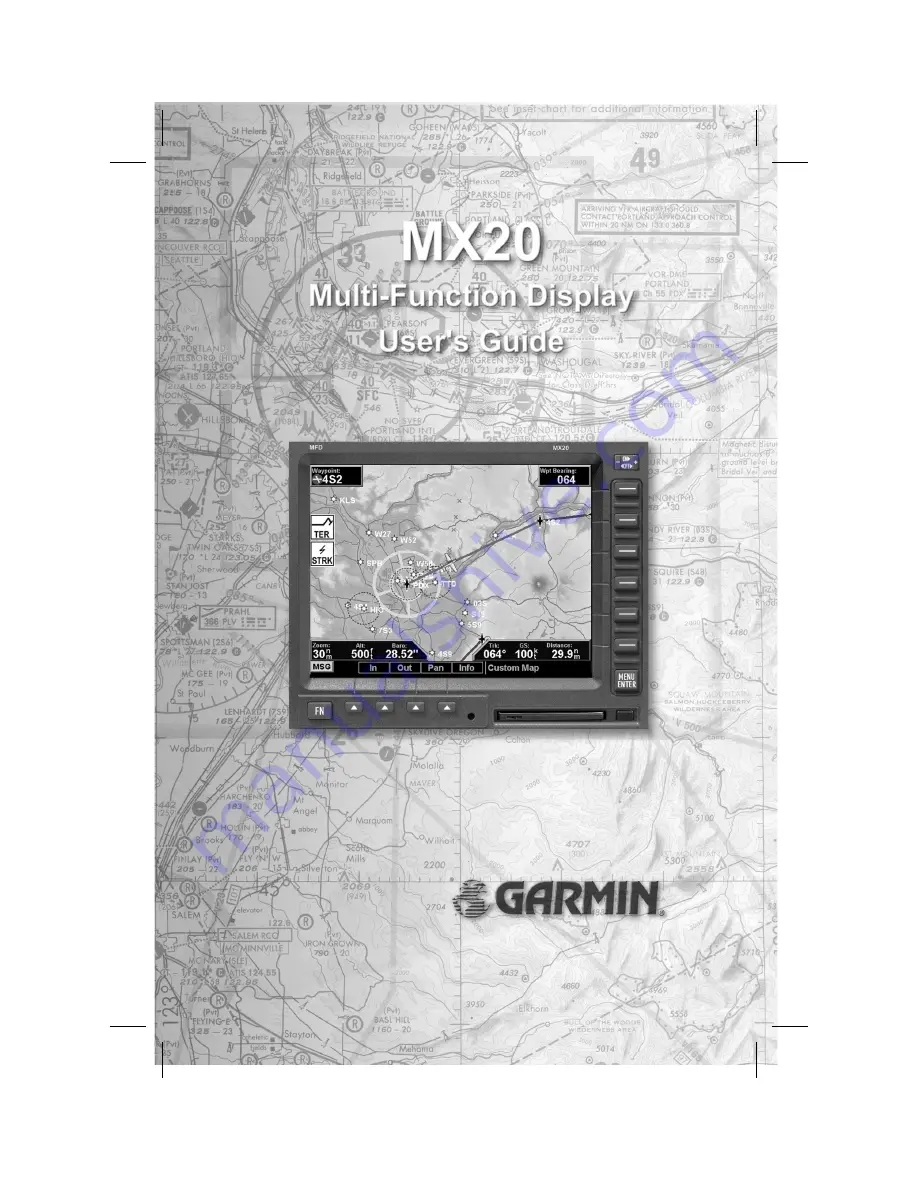
background image

Summary of Contents for MX20

Page 1: ......

Page 2: ...isseminated downloaded or stored in any storage medium for any purpose without the express written permission of Garmin Garmin hereby grants permission to download a single copy of this manual and of...

Page 3: ...6 04 April 2002 3 1 560 1026 04a June 2002 3 2 560 1026 04b November 2002 4 0 560 1026 05 February 2003 4 1 560 1026 05a June 2003 5 0 560 1026 05 Rev B September 2003 5 0 5 1 560 1026 05 Rev C Januar...

Page 4: ...uding but not limited to general special consequential or incidental damages including damages for loss of business profits business interruption loss of business information and the like arising from...

Page 5: ...can create a display for almost any configuration you require The other functions provide more limited levels of customization so that they retain the look and feel of the instruments they reflect The...

Page 6: ...ns Limitations The Traffic function is not a collision avoidance system It is an aid to visual acquisition and does not relieve the flight crew of their responsibility to see and avoid There are no ev...

Page 7: ...ags 8 Data Flags 9 Message Flag 10 Basic Operation 10 Power On 11 Pre Heat Mode 11 Brightness 12 Start Up Screen 12 Confirm Current Baro Correction 13 Function Selection 13 Advisory Hot Key 14 Alert H...

Page 8: ...Low Airways 32 High Airways 33 Water 33 Roads 33 Boundaries 33 Airport Chart 34 Terrain 35 Obstructions 35 Traffic 36 Strikes 36 IFR En Route IFR Chart Function 37 Flight Plan 37 Map Orientation 38 I...

Page 9: ...unction 50 Traffic Description 50 Flight Plan 53 Traffic Map Orientation 53 Display Mode 54 Label 54 Altitude Option Relative Pressure 54 Transmit Altitude 55 ADS B Broadcast Mode Control 56 Flight ID...

Page 10: ...Self Test 84 Noise Monitor 84 Strike Test 85 Antenna Change Message 85 Chart View CHART Function Optional 86 Overview 86 Chart Data Source 87 Chart Overlay in the Custom IFR Map 88 Viewing the Chart a...

Page 11: ...vailable to you for each function Press the FN key to show the available functions Press the smart key below the function label to go to the desired function While in each function press the MENU ENTE...

Page 12: ...ical profile across the bottom of the display The Traffic function when installed shows nearby traffic and details about each target The Flight Plan function provides details about your flight plan an...

Page 13: ...r on Press both the and rocker switches and hold them down to turn the power off Press the and rocker switches individually to adjust the display brightness manually Press the and rocker switches at t...

Page 14: ...sing the FN key Menu Enter The MENU ENTER key is located on the bottom right corner of the MX20 Press the MENU ENTER key to show a menu of options to modify the display of the current function Press t...

Page 15: ...to each option to scroll through the choices for each option Some options support tri state choices such as in Map mode When you select a tri state option the option label will change with each key p...

Page 16: ...t blunt object to press the data card ejector Gently pull the card straight out of the slot Insert a data card by pushing the card straight into the slot When fully inserted the data card and eject bu...

Page 17: ...e the function keys change to show the different choices for each function to allow access to commonly used actions A typical Custom Map function display is shown below See page 112 for details on dis...

Page 18: ...d 5 nm of your location This Traffic advisory is only available when the ADS B system with a UAT data link is installed and operational Refer to page 17 for a description of TIS A and TIS B Skywatch T...

Page 19: ...ltitude information is available from the external source Altitude related functions will not operate such as terrain awareness TRAF No traffic information is received from the optional external sourc...

Page 20: ...ilable from the optional external source XPDR No valid TIS A information is available from the optional external source See page 59 Message Flag The Message flag will appear on the lower left side of...

Page 21: ...unction Power On Turn the power rotary knob clockwise past the detent to turn the power on OR press the rocker switch to turn the power on The MX20 will progress through a series of startup screens Th...

Page 22: ...hes at the same time briefly to set the brightness automatically according to ambient light by th photo sensor Press the and rocker switches alone to adjust the display brightness manually When the br...

Page 23: ...e lower part of the display in blue Press the function key under the function label to activate that function The labels above the function key will change to reflect the custom smart controls for tha...

Page 24: ...ew of what is around the aircraft 3 When returning to the previous Function after viewing a Function with an advisory the original zoom and map mode will be restored This feature is designed to allow...

Page 25: ...s Also note that a pop up mode can be enabled on the Traffic function which makes the Traffic page pop up when a Traffic Advisory occurs The prompt or pop up mode is selected in the Traffic function O...

Page 26: ...ilized The Thumbnail provides a fixed 5nm range view of conflicting traffic and terrain The range depicted by the Thumbnail is not affected by the current zoom scale set on the main map functions Traf...

Page 27: ...lly the Thumbnail is disabled while operating on the ground This state is determined by the En Route Ground Transition Speed set in the System Function page and is based on GPS ground speed Traffic In...

Page 28: ...18 Getting Started...

Page 29: ...unction is selected The functions are described in the order that they appear A description of each function will be followed by an explanation of how the function smart keys operate for the function...

Page 30: ...until the message is viewed The MSG flag will remain in view while any messages remain in the message log New messages that have not been viewed will be highlighted as bold text 1 Press FN until you...

Page 31: ...the LINE SELECT key next to the displayed option Repeated presses of the LINE SELECT key will scroll through the available selections for each option The smart keys at the bottom of the display over t...

Page 32: ...roaching the waypoint the zoom level will not drop below 1 nm When the waypoint is reached and the next waypoint in the flight plan becomes active the zoom level will automatically adjust to bring tha...

Page 33: ...creen next to the LINE SELECT keys Move the map in the desired direction by pressing the LINE SELECT key next to the arrow that shows you want the map to move Press the PAN key again to exit the Pan m...

Page 34: ...Track Up or DTK Up Info In Pan Mode The INFO smart key supports operation in conjunction with the PAN feature On any of the maps Custom Map IFR and VFR entering the INFO mode while pan is active will...

Page 35: ...selection takes you to the next page of options The options have tri state choices that are also shown visually When the option is clear the icons and labels are not displayed When the option is solid...

Page 36: ...option to scroll through the options Invert The Invert option changes the display of text and the background color Depending on which layers are turned on inverting the display may help readability fo...

Page 37: ...aid in this fashion and only geo referenced charts will be presented for selection from the Custom Map Because of this it is possible that approach charts that are viewable under the Chart View Functi...

Page 38: ...f the Airport LINE SELECT option keys VORs The VORs option allows you to choose the type of VOR information displayed on the Map screen You may select the display of VOR icon and identifier icon only...

Page 39: ...MX20 highlights the VOR in magenta on the moving map when the SL30 is either tuned to or monitoring a nearby VOR station The highlighted VOR station is determined by using the tuned or monitored VOR f...

Page 40: ...d radial to help improve situational awareness The OBS line will only be drawn from the active VOR not the monitored VOR The SL30 must be receiving a valid signal from the VOR and the MX20 must have V...

Page 41: ...MX20 A published localizer back course approach at the airport is not necessary to enable this feature The SL30 must be receiving a valid ILS or localizer and the MX20 must have airports turned on for...

Page 42: ...enu items Custom Map Menu Option Page 3 The third option page of the Custom Map function lets you select options for the choices of Low Airways High Airways Water Roads and political boundaries The la...

Page 43: ...ing the LINE SELECT key next to Waters toggles between either the display or no display of the bodies of water Roads The Roads option allows you to control the display of interstate and state highways...

Page 44: ...ildings towers and other objects within the immediate airport vicinity From either the Custom Map or the IFR en route Map airport surface charts will automatically be loaded and displayed as an overla...

Page 45: ...blue Water will not be shown in relative mode Review the Limitations section on page iv Obstructions Obstructions such as towers and other man made objects are part of the MX20 updateable database Ob...

Page 46: ...In TCAD Skywatch and GTX330 installations the traffic targets can also be overlaid on the Custom Map page The Traffic function is not available in all software versions Check your Approved Flight Man...

Page 47: ...ata is advisory only and does not replace primary indicators such as the CDI Navigation should not be baesd on the data presented on the MX20 Review the Limitations section on page iv IFR Option Page...

Page 48: ...in the center Desired Track Up sets the desired track to the next waypoint as the top of the screen Press the LINE SELECT key next to this option to scroll through the options Invert The Invert optio...

Page 49: ...igh Airways Airport Chart and Terrain The last option selection takes you back to the first page of options Low Airways The Low Airways option allows you to control the display of Low Airways Pressing...

Page 50: ...chart A loaded chart is not being flown Load Chart Once the airport is selected the individual approach chart to be overlaid can be loaded from a list of geo referenced approach charts available for t...

Page 51: ...on or off Review the Limitations section on page iv for the limitations that apply to the data displayed on the moving map Flight Plan The Flight Plan option controls the display of the Flight Plan co...

Page 52: ...y for the current lighting conditions and the color of the terrain in a given area Nav Data The Nav Data option allows to control the display of navigation data on the Map displays Subsequent presses...

Page 53: ...lected to be shown on the lower portion of the display The profile view is only available when there is no TAWS sensor enabled and the Terrain function is based on the internal terrain database The pr...

Page 54: ...r half of the original display The image is not compressed from full width to half width Functions with an ownship symbol are displayed in Track Up map orientation and do not include the track line an...

Page 55: ...ns that apply to traffic data The traffic menu options vary depending on the traffic sources selected during the installation procedures but the display symbology is the same Traffic Depiction Your po...

Page 56: ...e corresponds to traffic generating an alerting condition Traffic shown with a cyan filled diamond corresponds to traffic generating an advisory condition Traffic shown with a cyan open diamond is con...

Page 57: ...er TAS Data Fail Skywatch Label set sent by the Skywatch unit has failed the integrity check Shown in amber TAS Time Out Skywatch MX20 is not receiving labels from the Skywatch unit Shown in amber No...

Page 58: ...000 vertical range to be filtered off the display The current mode is shown in the upper left corner of the display as ALL no filtering or 2000 when the filtering is active Volume The volume of the TC...

Page 59: ...r while absolute altitudes are shown as just a number Filter An altitude filter allows targets that are outside of a 2000 vertical range to be filtered off the display The current mode is shown in the...

Page 60: ...t an individual traffic target The Traffic function is not available in all software versions Review the Limitations section on page iv for the limitations that apply traffic data Traffic Description...

Page 61: ...ed to all aircraft in the area that are UAT data link equipped As TIS target location is determined by ground based radar coverage range and target positional accuracy are highly dependent on relative...

Page 62: ...90 UAT broadcasts the ident Operation The controls at the bottom of the screen allow you to zoom in and out initiate an Ident when connected to a GDL 90 UAT and to select each traffic target on the sc...

Page 63: ...ight Plan option controls the display of the Flight Plan course line Pressing the LINE SELECT key next to the Flight Plan option toggles between showing and not showing the Flight Plan route line Traf...

Page 64: ...ur current position shown on the top line The total number of targets tracked is shown in the upper left corner Up to 12 of the nearest targets are listed Label The LABEL menu key toggles the state of...

Page 65: ...n the baro corrected altitude shown on the altimeter in your aircraft Traffic Menu Option Page 2 The second menu option page of the Traffic function lets you select options for the choices of Transmit...

Page 66: ...during system install by the installer Broadcast VFR Causes a fixed Flight ID of VFR and a randomly generated ICAO address to be broadcast with the aircraft s current position This mode is similar to...

Page 67: ...end of the line shows the point where the traffic item will be at the end of the selected time interval Select 1 1 5 2 5 or 10 minutes Press the Main Menu LINE SELECT key to display the next page of m...

Page 68: ...the CANCEL smart key When a special service code is being transmitted the services label is illuminated To terminate the broadcast press the SERVICES option again Once terminated the code will revert...

Page 69: ...s are available for adjusting traffic presentation and sensor operation Review the Limitations section on page iv for the limitations that apply to traffic data Important Note TIS A is not a collision...

Page 70: ...de meaning that track based flight plan information is not overlaid Traffic can also be shown on the Custom Map and in a small thumbnail view presented in the upper left corner of the screen Traffic t...

Page 71: ...affic function screen when a Traffic Advisory TA alert is received from the TIS A sensor You may then view another function by pressing the FN key and selecting the desired function Operate Standby Th...

Page 72: ...as missed a radar sweep Target brightness is also reduced to indicate this condition TIS Unavailable to indicate the TIS A sensor is operating but outside of TIS A service coverage TIS Standby to indi...

Page 73: ...Current Flight Plan box shows all of the legs of your flight plan with the current leg indicated in magenta Listed are each leg with the bearing and distance between the legs The Current Nav Data box...

Page 74: ...ernal MX20 Based Terrain The altitude information comes from an external altitude encoder The displayed altimeter setting has to be adjusted or baro corrected just like the one in your aircraft s inst...

Page 75: ...the screen Use the BARO and BARO keys at the bottom of the screen to make minor adjustments to the barometric pressure value 65 Detailed Operation 500 feet below your current altitude Yellow 2000 fee...

Page 76: ...your current altitude LIGHT BLUE No terrain data is available Terrain Option Page The Terrain option page lets you select options for the choices of Flight Plan Map Orientation and setting the baromet...

Page 77: ...ic pressure for your area or adjust the current value This option is best for making large changes The BARO and BARO keys are more useful for minor corrections Use the UP DOWN arrow keys to increase o...

Page 78: ...in the proximity of the aircraft See the Pilots Guide for the Goodrich Landmark for additional information on how to interpret this information Note When the MX20 is configured for an external Terrain...

Page 79: ...rainfall progresses from light green for light rainfall to magenta for heavy rainfall Review the Limitations section on page iv for the limitations that apply to the FIS data Rainfall data is color c...

Page 80: ...thin reception range of the Ground Broadcast Transceiver GBT If any weather data has been received in the previous two minutes the Service indicator in the lower left of the screen will display Availa...

Page 81: ...y to the FIS data Product Times Product times shown on the lower portion of the display are GM for Graphical METARs RD for weather radar ETP for EchoTops and WB for Warning Boxes Times are Zulu times...

Page 82: ...ity is presented and is an indication of radar echo return strength The same colors are used for US and Canadian weather Because of weather radar differences do not assume that the same actual weather...

Page 83: ...red circles or diamonds at airports that provide METAR reports Press the METARs Line Select key to cycle through the options of circular diamond or no METARs Refer to the Legend for a description of t...

Page 84: ...strictions TFRs indicate areas where flight restrictions have been imposed They are depicted as areas with reddish brown outlines and a cross hatch pattern The area may also contain the TFR identifier...

Page 85: ...course line on and off The magenta line is the active leg Legend Press MENU ENTER key and then press the LEGEND Line Selection key to display the legends describing the graphic display colors Press t...

Page 86: ...MENU ENTER key and then press the Map Detail Line Selection key to choose between the display of No Overlays the Base Map or Map and Nav Aids Map Orientation Press MENU ENTER key and then press the Ma...

Page 87: ...SLE 191534Z METAR TEXT METAR KMMV 181423Z METAR TEXT TAF KSLE 171423Z TAF TEXT The upper portion of the FIS Function page is used for displaying the contents of an individual FIS message while the low...

Page 88: ...noted by a green circle with an I inside The pilot is able to move the green Selection Pointer within the lower portion of the page to select the desired category location and time that is of interes...

Page 89: ...ssed the currently viewed message is presented in a full screen mode This feature provides a mechanism to view large textual messages that do not fit within the upper half of the display area Some mes...

Page 90: ...ance to Nearest Present Position Distance to Nearest Final Waypoint Distance to Nearest Next Waypoint Alphanumerically When the sorting is based on distances from current ownship to a given airport th...

Page 91: ...our position The Lightning function is not available in all software versions Your display range must be selected to be greater than 25 nm to display lightning strikes The display range is shown in th...

Page 92: ...System Data info The last option selection Next Page takes you to the next page of options 82 Detailed Operation...

Page 93: ...The WX500 detects electrical discharges within a range determined by the installation of your Stormscope These discharge locations are noted as Lightning strikes and displayed as a red x You may selec...

Page 94: ...strikes Self Test The Self Test option performs a number of tests on the operation of the WX500 and provides a report of its status Noise Monitor The Noise Monitor feature is a function of the WX500...

Page 95: ...e WX500 Test strikes are sent to the antenna The received test strike is then visually presented on the screen Antenna Change Message When an Antenna Change message is shown the lightning sensor may h...

Page 96: ...eppesen on a two week schedule The in flight data resides on the pilot removable front loading data card and is updated by the pilot using a home PC based data loader The MX20 Chart View feature does...

Page 97: ...electronic form from the Jeppesen JeppView product are available for loading onto the MX20 platform These consist of approaches SIDS STARS airspace charts and airport surface diagrams The MX20 can dis...

Page 98: ...harts that can apply for a given region i e multiple approach charts for the same airport An approach chart will be displayed as an overlay when the following conditions are met The approach chart is...

Page 99: ...list will vary depending on the complexity of the database within the current region and the number of geo referenced approach charts associated with the airports in the area The MX20 performs a comp...

Page 100: ...indicating the airport name and specific chart that has been loaded Overlay Chart Loading Example 1 Press FN and then MAP or IFR 2 Press MENU and then the LOAD CHART Line Select key 3 Highlight the d...

Page 101: ...the coverage area the chart contents will be displayed on the screen Note that a loaded approach chart is only viewable from the maps when the aircraft is in flight otherwise the airport surface chart...

Page 102: ...d Entering the panning mode will disable the display of the chart and allow the underlying map layers to be presented Chart Orientation When the chart overlay is presented the orientation is identical...

Page 103: ...erations and can be used as an actual overlay on the maps Loading a chart through the Chart View Function is identical to loading a chart from the Custom IFR map as described in previous sections All...

Page 104: ...key and use the movement Line Select keys on the right side of the display Use the INFO smart key to step through the different details of the chart Menu Items Search ID The Search ID menu option with...

Page 105: ...this list a circular earth symbol indicates that the chart is geo referenced and therefore can be loaded for use as an overlay on the maps If a red X is presented through the earth symbol then that sp...

Page 106: ...is turned on meaning that the airport surface map is displayed as soon as GPS position is acquired Note that the Zoom Scale Auto Transition feature determines the initial zoom scale that is set when t...

Page 107: ...ght including on the ground before takeoff Note that the approach will not be shown on the map itself until the aircraft s speed is above the air ground speed threshold The approach will be automatica...

Page 108: ...ed In this case the automatic transition to surface maps does not occur and the approach is not automatically un loaded See the Initial Zoom and Transition Speed selection in the System Function Page...

Page 109: ...reshold the display will automatically transition to the en route zoom mode of AUTO and adjust the display to show the current destination waypoint Typical Approach Scenario Setting the destination wa...

Page 110: ...RT2000 weather radar is seamlessly integrated with the other functionality of the MX20 with a RADAR option available from the main function menu Note that auto tilt is not supported for the ART2000 21...

Page 111: ...and may display test data on the MX20 The radar unit will go to the Standby mode once it has completed the self test procedure Selections can be made to command the unit into one of the following init...

Page 112: ...her mode or any other time the radar is transmitting a green RDR indicator is presented in the upper left corner of the display MAP Mode The Map MAP mode is used for obtaining returns from the ground...

Page 113: ...R Gain Control Available only when the MAP mode is current the gain is used to adjust the sensitivity of the radar receiver It can be used in map mode to adjust the characteristics of the returns from...

Page 114: ...is occurring a cursor line can be activated to pre select a specific tilt to a weather cell of interest Once selected changing the scan mode to horizontal will automatically set the tilt angle of the...

Page 115: ...aircraft on the display You can make selections of Single Twin Jet or Helicopter Lat Lon Format The Lat Lon format option allows you to select between two choices for the display of Lat Lon coordinate...

Page 116: ...to save the changed values and leave the Set Baro Correction option Display Latitude Longitude Lines Use this option to choose to display or not display Lat Lon lines on the map displays Initial En Ro...

Page 117: ...transition point are adjusted under the SYS Function En Route Ground Transition Speed 10 100 kts Initial En Route Zoom Scale Auto 0 25 250 nm Initial Ground Zoom Scale 0 25 5 nm The recommended settin...

Page 118: ...t to instruct the MX20 to load a selected approach chart Display ICAO for US Airports Press the Line Selection key to toggle on off the display of ICAOs for US airports When enabled the leading K char...

Page 119: ...stalls the SYS INFO page shows additional details for both the internal GPS engine and the data link status When the MX20 is connected to a legacy UAT the ADS B and TIS B Data Link Status lines are di...

Page 120: ...oadcast packets received TIS B TIS B broadcast packets received legacy UAT only FIS TX Textual weather data packets received FIS WX Graphical weather data packets received System Test Page The System...

Page 121: ...o verify proper operation of the display or when contacting Customer Service Red Green Blue White Test Pattern Choosing the Red Green Blue or White options floods the screen with the selected color Us...

Page 122: ...to condense moisture on the display and then wipe the area with the clean fabric Moisten a clean fabric with a small amount of water and wipe the display area Apply a small amount of glass cleaner wit...

Page 123: ...section Be sure to have the information from the System Info page see page 109 and the data card available before you contact your dealer or the factory Problem Possible Cause Action Unit does not po...

Page 124: ...k for any interference sources Have dealer installer check for proper MX20 setup RTE Route flag Position source route Ensure that the external position source has an active route engaged ALT Altitude...

Page 125: ...system installed If you do have an ADS B system check the antennas and other components for proper operation Have dealer installer check for proper MX20 setup Special Terrain message Capstone General...

Page 126: ...eporting a position or is reporting an invalid position Note that ADS B broadcasts do not include position reports when this flag is present Ensure the GDL 90 is installed and functional Ensure the GD...

Page 127: ...ing the factory 112 Controls 3 D Data card 6 87 113 Data flags 9 Data port status 109 Database version 109 Data link 109 Demo 84 Desired track up 26 38 42 Display 54 Care 112 Graphic 54 Text 54 Displa...

Page 128: ...Services 58 Set baro 106 SKYW 9 Skywatch 8 36 45 47 SL30 28 Software version 109 Start Up 12 Stormscope 2 81 83 84 Strike 83 Strike test 85 Strikes 36 Surface targets 52 System 105 Data 83 Info 109 T...

Page 129: ......

Page 130: ...2004 by Garmin Corporation Inc 1200 East 151st Street Olathe KS 66062 3426 U S A Phone 913 397 8200 FAX 913 397 8282 http www garmin com Part 560 1026 06 Rev May 2004...

Reviews: