Garrecht Avionik VOLKSLOGGER, User Manual
Get your hands on the Garrecht Avionik VOLKSLOGGER user manual for free download at 88.208.23.73:8080. This essential manual provides detailed instructions on how to operate and make the most out of your VOLKSLOGGER device. Don't miss out on this valuable resource - download your manual today!
Share
Download


Reviews:
No comments
Related manuals for VOLKSLOGGER

ROSSINI
Brand: Costan Pages: 41

VALZER KW
Brand: Kysor/Warren Pages: 33

WDCG Series
Brand: BKI Pages: 39

G500
Brand: Garmin Pages: 76

MCP combo panel
Brand: VRinsight Pages: 24
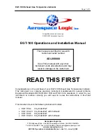
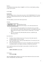
EGT-100 Series
Brand: Aerospace Logic Pages: 11
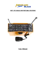
ART-27C
Brand: Aeroplans Blaus Pages: 4
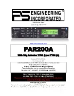
PAR200A
Brand: PS Engineering Pages: 41

RoadRunner AFI4700
Brand: Astronautics Pages: 91


