


Index
Contexts
................................................................ ………….
Chapter – Page
1
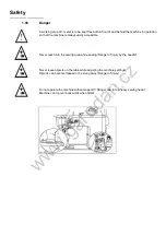
Safety
........................................................................….............…………..…….1 - 1
1
.01
Directives..........................……..................…......................................……..…...1 - 1
1
.02
General notes on safety.........................…….….....................................………..1 - 1
1
.03
Safety symbols.................................................................................……….…… 1 - 2
2
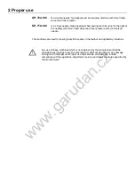
Proper use
……............................................................................…….....…...... 2 - 1
3
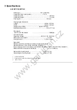
Specifications
………......................................................................……........... 3 - 1
3
.01
GP-710-148, GP-724-108.......................................…....................................…. 3 - 1
3
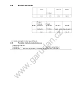
.02
Needles and threads …………...................................................…...…..........…. 3 - 2
3
.03
Possible models and subclasses ………..........................................…..........….. 3 - 2
4
Explanation of symbols
……………...…........................................................... 4 - 1
5
Controls
……….................................................................................................. 5 - 1
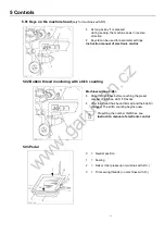
5.
01
Keys on machine head (only for machines with -D3/.. ) …………....................... 5 - 1
5.
02
Bobbin thread monitoring with stitch counting ………….............…..................... 5 - 2
5.
03
Pedal …......................................................................…....….............................. 5 - 2
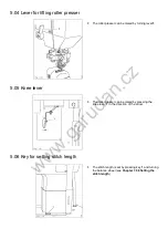
5.
04
Lever for lifting roller presser …………........................……................................. 5 - 3
5.
05
Knee lever .................................................................…...................................... 5 - 3
5.
06
Dey for seeting stitch length ……….................................................................. 5 - 4
5.
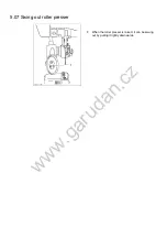
07
Swing out roller presser ............................…..............................…..................... 5 - 4
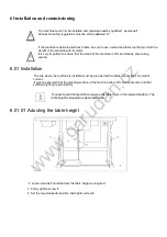
6
Installation and commissioning
...................……………..........….........……... 6 - 1
6
.01
Installation..................................……................................….............................. 6 - 1
6
.01.01
Adjusting the table height.............................................…...…..............…......…. 6 - 1
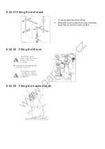
6
.02
Fitting the reel stand ...........................………….............................…................. 6 - 2
6
.03
Tilted work base ..................................……................................…….............…. 6 - 3
6.
04 Table top cutout ......................……..…............................................................ 6 - 4
6
.05
Mounting the table top...............……………...............................…..................... 6 - 5
7
Preparation.
........................................................…............................................ 7 - 1
7
.01
Inserting the needle on model GP-710…............................................................ 7 - 1
7
.02
Inserting the needle on model GP-724........................…………......................... 7 - 2
7
.03
Winding the bobbin thread; adjusting the bobbin thread tension .........…........... 7 - 3
7
.04
Removing/Inserting the bobbin case .......………………….................................. 7 - 4
7
.05
Threading the bobbin case/Adjusting the bobbin thread tension ..................... 7 - 4
7
.06
Threading the needle thread and regulating its tension on model GP-710……....7 - 5
7
.07
Threading the needle thread and regulating its tension on model GP-724......... 7 - 6
7
.08
Setting the stitch length ....................................................……….................…... 7 - 7
8
Care and maintenance ..
.....................................………........…..................… 8 - 1
8.
01
Checking/adjusting the air pressure....................................................................8 - 1
8.
02
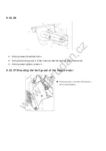
Cleaning the air filter of the air-filter/lubricator............... ...............................…..8 - 2
8.
03
Cleaning ...............................................…......................…................................ 8 - 3
8.
04
Oiling the hook ....................…....................…................................................... 8 - 4
8.
05
Oil bowl for hook lubrication....….…….....……………………....…….................. 8 - 4
8.
06
Filling the oil reservoir of the thread lubrication unit ..............………................. 8 - 5
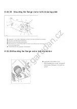
8.
07
Lubricating the bevel gears ............................................…………..................... 8 – 6
9
Adjustment
..............................………............................................................... 9 - 1
9.
01
Notes on adjustment............................…............................................................ 9 - 1
www.garudan.cz